EP2336488A2 - Porte-pic et élément de base - Google Patents
Porte-pic et élément de base Download PDFInfo
- Publication number
- EP2336488A2 EP2336488A2 EP10188978A EP10188978A EP2336488A2 EP 2336488 A2 EP2336488 A2 EP 2336488A2 EP 10188978 A EP10188978 A EP 10188978A EP 10188978 A EP10188978 A EP 10188978A EP 2336488 A2 EP2336488 A2 EP 2336488A2
- Authority
- EP
- European Patent Office
- Prior art keywords
- support
- plug
- receptacle
- projection
- base part
- Prior art date
- Legal status (The legal status is an assumption and is not a legal conclusion. Google has not performed a legal analysis and makes no representation as to the accuracy of the status listed.)
- Granted
Links
Images


Classifications
-
- E—FIXED CONSTRUCTIONS
- E21—EARTH OR ROCK DRILLING; MINING
- E21C—MINING OR QUARRYING
- E21C35/00—Details of, or accessories for, machines for slitting or completely freeing the mineral from the seam, not provided for in groups E21C25/00 - E21C33/00, E21C37/00 or E21C39/00
- E21C35/18—Mining picks; Holders therefor
-
- E—FIXED CONSTRUCTIONS
- E21—EARTH OR ROCK DRILLING; MINING
- E21C—MINING OR QUARRYING
- E21C35/00—Details of, or accessories for, machines for slitting or completely freeing the mineral from the seam, not provided for in groups E21C25/00 - E21C33/00, E21C37/00 or E21C39/00
- E21C35/18—Mining picks; Holders therefor
- E21C35/19—Means for fixing picks or holders
- E21C35/193—Means for fixing picks or holders using bolts as main fixing elements
-
- B—PERFORMING OPERATIONS; TRANSPORTING
- B28—WORKING CEMENT, CLAY, OR STONE
- B28D—WORKING STONE OR STONE-LIKE MATERIALS
- B28D1/00—Working stone or stone-like materials, e.g. brick, concrete or glass, not provided for elsewhere; Machines, devices, tools therefor
- B28D1/18—Working stone or stone-like materials, e.g. brick, concrete or glass, not provided for elsewhere; Machines, devices, tools therefor by milling, e.g. channelling by means of milling tools
- B28D1/186—Tools therefor, e.g. having exchangeable cutter bits
- B28D1/188—Tools therefor, e.g. having exchangeable cutter bits with exchangeable cutter bits or cutter segments
-
- E—FIXED CONSTRUCTIONS
- E02—HYDRAULIC ENGINEERING; FOUNDATIONS; SOIL SHIFTING
- E02F—DREDGING; SOIL-SHIFTING
- E02F9/00—Component parts of dredgers or soil-shifting machines, not restricted to one of the kinds covered by groups E02F3/00 - E02F7/00
- E02F9/28—Small metalwork for digging elements, e.g. teeth scraper bits
- E02F9/2808—Teeth
- E02F9/2816—Mountings therefor
-
- E—FIXED CONSTRUCTIONS
- E02—HYDRAULIC ENGINEERING; FOUNDATIONS; SOIL SHIFTING
- E02F—DREDGING; SOIL-SHIFTING
- E02F9/00—Component parts of dredgers or soil-shifting machines, not restricted to one of the kinds covered by groups E02F3/00 - E02F7/00
- E02F9/28—Small metalwork for digging elements, e.g. teeth scraper bits
- E02F9/2808—Teeth
- E02F9/2858—Teeth characterised by shape
-
- E—FIXED CONSTRUCTIONS
- E02—HYDRAULIC ENGINEERING; FOUNDATIONS; SOIL SHIFTING
- E02F—DREDGING; SOIL-SHIFTING
- E02F9/00—Component parts of dredgers or soil-shifting machines, not restricted to one of the kinds covered by groups E02F3/00 - E02F7/00
- E02F9/28—Small metalwork for digging elements, e.g. teeth scraper bits
- E02F9/2866—Small metalwork for digging elements, e.g. teeth scraper bits for rotating digging elements
-
- E—FIXED CONSTRUCTIONS
- E21—EARTH OR ROCK DRILLING; MINING
- E21C—MINING OR QUARRYING
- E21C35/00—Details of, or accessories for, machines for slitting or completely freeing the mineral from the seam, not provided for in groups E21C25/00 - E21C33/00, E21C37/00 or E21C39/00
- E21C35/18—Mining picks; Holders therefor
- E21C35/19—Means for fixing picks or holders
- E21C35/191—Means for fixing picks or holders for fixing holders
-
- E—FIXED CONSTRUCTIONS
- E21—EARTH OR ROCK DRILLING; MINING
- E21C—MINING OR QUARRYING
- E21C47/00—Machines for obtaining or the removal of materials in open-pit mines
-
- E—FIXED CONSTRUCTIONS
- E21—EARTH OR ROCK DRILLING; MINING
- E21C—MINING OR QUARRYING
- E21C47/00—Machines for obtaining or the removal of materials in open-pit mines
- E21C47/02—Machines for obtaining or the removal of materials in open-pit mines for coal, brown coal, or the like
Definitions
- the invention relates to a bit holder with a plug projection and a holding lug, wherein the holding lug has a chisel receptacle, and wherein the holding lug projecting in the tool feed direction at least partially from or over the plug approach.
- the invention also relates to a base part with a plug-in receptacle and a support lug, which forms a support.
- Such bases are used to hold chisel holders.
- the base part has a plug-in receptacle, to the front side a base part section is connected with a threaded receptacle.
- the threaded receptacle opens into the socket.
- the bit holder is equipped with a plug-in projection, which can be inserted into the socket of the base part.
- a Holding attachment connected, which is provided with a bit holder in the form of a through hole. The holding approach is partially in the tool feed direction on the plug approach. Contrary to the feed direction both the retaining lug and the plug-in approach are provided with support surfaces.
- a screw is screwed into the threaded receptacle of the base part. This presses the chisel holder with its support surfaces to correspondingly shaped mating surfaces of the base part.
- a force acts on the bit which is inserted in the bit holder. This arises when the bit engages in the material to be removed. In this case, the force direction varies during the tool attack, whereby in particular an alternating stress arises. It has been found that in such tool combinations, due to the alternating stress, the fastening screw can be solved, whereby the bit holder is no longer securely fixed in the base part.
- such bit holder for mining work with high tool delivery, as required for example in surface mining, not sufficiently dimensioned. In particular, often results in the transition region between the holding lug and the plug approach tool breakage.
- Dovetail connections between the base part and the bit holder are also known from the prior art. Such a configuration is for example in the US 4,915,455 shown. These dovetail joints are very vulnerable. As a result of the alternating stress, the mating surfaces between the base part and the bit holder knock out, resulting in premature failure of the system.
- the task relating to the bit holder is achieved in that the retaining projection has a support section with a support surface, which is arranged in the feed direction at least partially in front of the plug approach.
- the projecting in the direction of the part of the holding lug can be intercepted with its rigid, molded support surface on a correspondingly shaped abutment of a base part.
- the location of the transmission of the maximum forces occurring during the use of tools is placed close to the chisel head. This results in a significant reduction in the effective torques.
- This strength-optimized design of the chisel holder leads to significantly longer service life and increases operational safety.
- the support portion has two support surfaces which are at an angle to each other.
- This arrangement can withstand high loads even when acting transversely to the main direction.
- the support surfaces are arranged on both sides of the center transverse plane extending through the central longitudinal axis of the bit receptacle and in the direction of the longitudinal extent of the insertion projection.
- a conceivable variant of the invention provides that the support surface or the support surfaces form a sliding guide whose sliding direction runs counter to the tool feed direction (v).
- v tool feed direction
- the support surface or the support surfaces form a sliding guide whose sliding direction runs counter to the tool feed direction (v).
- the support surface or the support surfaces is part of a broadening (projecting) in the direction transverse to the central longitudinal axis of the bit holder on the bit holder.
- the spacers form Spanableit vom that protect a base part from abrasive wear attack.
- a conceivable alternative of the invention may be such that the plug-in projection has at least one pressure surface in the area of its plug projection front side pointing in the tool feed direction, which is arranged at an angle of less than 90 °, preferably less than 80 °, to the central longitudinal axis of the plug-in projection.
- This pressure surface serves to clamp the chisel holder with a base part.
- Einzug can be introduced in the direction of the longitudinal axis of the plug-in projection on the pressure surfaces (for example, with a pressure screw).
- the insertion projection preferably has a further support section with one or more bearing surfaces in the area of its plug projection rear side facing away from the tool feed direction.
- bearing surfaces are at an angle to each other, which in turn creates a centering of the chisel holder relative to the base part, as well as an optimized power dissipation by large transmission surfaces for the forces acting.
- the bearing surfaces extend substantially in the direction of the longitudinal axis of the plug-in projection.
- a sliding guide is generated in plug-way longitudinal direction. If, due to wear, a base part in the area of its support section assigned to the chisel holder wears on the front side, the usability of the base part for new, unset chisel holder still remains. Over the back sliding guide the Nachsetz can be compensated.
- the object of the invention relating to the base part is achieved in that the support lug forming the support is arranged in the tool advance direction in front of the socket and the support is formed in front of the socket.
- the base part thus offers the possibility of a power-optimized dissipation of the forces, since the support lug can be brought with its support close to the chisel tip.
- the support forms a support surface which forms an obtuse angle with the longitudinal axis of the plug attachment.
- this obtuse angle which should preferably extend in the range between 200 ° and 250 °, an optimized on the varying force direction during the use of tools power transfer is possible. If it is provided that opposite to the feed direction behind the plug-in receptacle is arranged, which holds at least one counter-bearing in the socket, then the above-mentioned double support a chisel holder is possible. In particular, this front side can be clamped to the support lug and the back of the abutment. As a result, on the one hand large-area force transmission surfaces are created, on the other hand, varying force directions can be optimally intercepted.
- a preferred embodiment of the invention is such that the support and / or the abutment has two support surfaces that are at an angle to each other. About this support surface arrangement, a centering of the bit holder is achieved with respect to the base part. In addition, large power transmission surfaces are possible via the slanted support surfaces.
- the angle arrangement can be chosen so that with a small volume of construction a strength-optimized design of the base part is possible.
- a variant of the invention is such that the support projection in the tool feed direction in front of the plug-in receptacle has a screw receptacle which opens into the region of the plug receptacle.
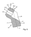
- FIG. 3 shows, the base part 10 on a plug-in receptacle 15 which receives a plug 21 of the chisel holder 20.
- FIGS. 4 to 6 the design of the bit holder 20 explained in more detail.
- the bit holder 20, the plug approach 21, at the angle of a holding lug 25 is connected.
- an obtuse angle is included between the plug 21 and the retaining lug 25.
- the plug-in projection 21 forms in the region of its, in the tool feed direction (v) facing plug approach front 22 a front surface 21.1.
- two recesses are recessed so that they form pressure surfaces 21.2.
- the pressure surfaces 21.2 are arranged at an angle to the longitudinal axis of the plug-in projection 21.
- the pressure surface 21.2 bearing projection of the plug 21 passes through lateral transition sections 21.3 in side surfaces 21.4 over. In this case, the side surfaces 21.4 are aligned in the direction of the tool feed direction (v) and point to the tool sides.
- FIG. 5 can recognize the side surfaces go 21.4 in the area of the plug projection rear side 23 in bearing surfaces 21.5 over.
- the storage areas 21.5 are at an angle to each other.
- the bearing surfaces 21.5 in turn are connected by means of a transition surface 21.6 and have opposite to the feed direction v.
- the retaining lug 25 is provided with a bit holder 26 in the form of a cylindrical bore.
- the central longitudinal axis M of the bit receptacle 26 and the longitudinal axis L of the plug-in projection 21 ideally enclose an angle in the range between 100 and 160 °, preferably 130.
- the bit receptacle 26 merges via an introducer extension 27 into a bearing surface 25.3.
- the support surface 25.3 extends radially to the chisel receiver 26.
- the chisel holder 26 faces away from the support surface 25.3 in a cross-sectional taper 25.1.
- the cross-sectional taper 25.1 is designed in the form of a truncated cone and leads the lateral surface (25.2) of the chisel holder 20 into the bearing surface 25.3.
- the retaining lug 25 has in the region below the bit holder 26 two support surfaces 29, which are employed in an angle to each other in a V-shape. Show how the FIG. 6 can recognize the support surfaces 29 due to their oblique position in the direction of the free end of the plug-in approach and at the same time in the feed direction (v) and run, as in FIG. 3 represented, parallel or substantially parallel to the central longitudinal axis M of the bit holder 26. Like the FIG. 5 can recognize, has the retaining lug 25 lateral widening 28 in which the support surfaces 29 expire. The support surfaces 29 and the bearing surfaces 21.5 are oriented pointing in opposite directions.
- the base part 10 has a plug-in receptacle 15 which is adapted in its cross-section to the outer contour of the plug-in projection 21 of the bit holder 20. Front side, the plug-in receptacle 15 is limited by means of a support projection 12.
- a screw 13 is incorporated as a thread.
- the screw receptacle 13 opens into the plug-in receptacle 15.
- the plug receptacle 15 faces away from the screw receptacle 13 in a bore enlargement 13.1.
- the support lug 12 has in its upper, radially outer region on a support 18 which is formed by two support surfaces 18.1.
- the two support surfaces 18.1 are employed at an angle to each other.
- the angular orientation of the support surfaces 18.1 is adapted to the orientation of the support surfaces 29 of the chisel holder 20, so that the support surfaces 29 of the chisel holder 20 can rest plane-parallel on the support surfaces 18.1 of the base member 10.
- the support surfaces 18.1 are for the purpose of the defined investment of the bit holder 20 via a recessed paragraph 18.4 connected to each other.
- the plug-in receptacle 15 is delimited by an abutment 16.
- the anvil 16 is part of a rear projection 17 which protrudes counter to the feed direction (v) via the plug-in receptacle 15.
- the anvil 16 is formed by two further support surfaces 16.1, which are at an angle to each other. These further support surfaces 16.1 are again adapted in their design and spatial arrangement adapted to the bearing surfaces 21.5 of the bit holder 20, so that a plane-parallel contact the other bearing surfaces 21.5 on the support surfaces 16.1 is possible.
- Opposite the support surfaces 18.1, the plug-in receptacle 15 is bounded by an open space 18.2.
- the plug-in receptacle 15 is bounded by two lateral connecting sections 19.
- the inner surfaces formed by the connecting sections 19 and facing the plug-in receptacle 15 pass over open spaces 18.5 into walls 18.6, which in turn are oriented in the tool feed direction (v).
- the walls 18.6 turn out in the open space 18.2.
- the mounting of the bit holder 20 on the base part 10 is carried out as follows.
- the bit holder 20 is inserted with its plug 21 in the socket 15 of the base member 10.
- the fastening element 14 has a pressure surface oriented at right angles to the screw axis, which abuts the pressure surface 21. 2 of the chisel holder 20.
- the pressure surface does not have to be a flat surface, but can also be a spherical surface.
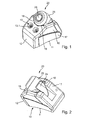
- the FIG. 1 shows that two fastening elements 14 are used for fastening the chisel holder 20, thus also two screw receptacles 13 are incorporated into the base part 10.
- the fastening element 14 presses against the pressure surface 21.2. Due to the angular position of the pressure surface 21.2 to the central longitudinal axis of the plug 21, the fastener 14 exerts a pull-in force on the plug 21. At the same time a force component is generated, which is opposite to the feed direction (v) and presses the plug 21 in the counter-bearing 16. The extending in the direction of the longitudinal axis of the plug 21 force component brings the support surfaces 18.1 of the support 18 with the support surfaces 29 of the chisel holder 20 to the plant. A tension of the fasteners 14 now causes, as in particular from FIG.
- the bit holder 20 experiences a support on both sides of the central longitudinal axis of the plug-in projection 21.
- the support on the anvil 16 is made on the rear side of the central longitudinal axis and on the other on the support 18 on the front side of the central longitudinal axis.
- the fastening screw 14 now acts on the insertion projection 21 such that a tensioning of the bit holder 20 takes place on the support 18 and the abutment 16. In this way, a secure and captive attachment of the chisel holder 20 is guaranteed.
- FIG. 3 can further recognize that in the bore extension 13.1 of the screw 13, a cover 14.1 can be used, which covers the tool holder of the fastener 14.
- Both the base part 10 and the bit holder 20 are formed essentially mirror-symmetrically to the transverse direction of the medium in the direction of advance (v) of these respective components. This promotes a uniform load transfer.
- FIG. 3 can recognize a unique assignment of the bit holder 20 to the base part 10 in particular guaranteed by the fact that only one edition of these two above-mentioned central support points takes place (support 18 and thrust bearing 16).
- the free space 18.2 the walls 18.6 of the open spaces 18.5 and the connecting portion 19 of the plug 21 is released from the socket 15. If, for example, a wear of the support surfaces 18.1 takes place in the course of the use of the base part 10, the paragraph 18.4 forms a reset space.
- the spacing of the bit holder 20 from the paragraph 18.4 guarantees a repositioning of the bit holder 20 in case of wear.
- the built-in round shank chisel removes material which slides off the chisel holder 20 in the area of the lateral surface 25.2.
- This space material is passed through the spacers 28 to the outside, whereby a protection of the base member 10 is effected before the abrasive attack of this space material.
Landscapes
- Engineering & Computer Science (AREA)
- Mining & Mineral Resources (AREA)
- General Engineering & Computer Science (AREA)
- Structural Engineering (AREA)
- General Life Sciences & Earth Sciences (AREA)
- Geochemistry & Mineralogy (AREA)
- Geology (AREA)
- Civil Engineering (AREA)
- Mechanical Engineering (AREA)
- Life Sciences & Earth Sciences (AREA)
- Drilling And Exploitation, And Mining Machines And Methods (AREA)
- Percussive Tools And Related Accessories (AREA)
- Cutting Tools, Boring Holders, And Turrets (AREA)
- Earth Drilling (AREA)
- Jigs For Machine Tools (AREA)
- Details Of Spanners, Wrenches, And Screw Drivers And Accessories (AREA)
- Milling Processes (AREA)
Applications Claiming Priority (1)
| Application Number | Priority Date | Filing Date | Title |
|---|---|---|---|
| DE102009059188A DE102009059188A1 (de) | 2009-12-17 | 2009-12-17 | Meißelhalter und Basisteil |
Publications (3)
| Publication Number | Publication Date |
|---|---|
| EP2336488A2 true EP2336488A2 (fr) | 2011-06-22 |
| EP2336488A3 EP2336488A3 (fr) | 2016-06-29 |
| EP2336488B1 EP2336488B1 (fr) | 2019-05-15 |
Family
ID=43825263
Family Applications (1)
| Application Number | Title | Priority Date | Filing Date |
|---|---|---|---|
| EP10188978.0A Active EP2336488B1 (fr) | 2009-12-17 | 2010-10-27 | Porte-pic et élément de base |
Country Status (10)
| Country | Link |
|---|---|
| US (1) | US8746806B2 (fr) |
| EP (1) | EP2336488B1 (fr) |
| JP (1) | JP5425047B2 (fr) |
| KR (1) | KR101388232B1 (fr) |
| CN (3) | CN102102516B (fr) |
| AU (1) | AU2010246502B2 (fr) |
| CA (1) | CA2722823C (fr) |
| DE (1) | DE102009059188A1 (fr) |
| RU (1) | RU2457327C1 (fr) |
| TW (1) | TWI470148B (fr) |
Cited By (1)
| Publication number | Priority date | Publication date | Assignee | Title |
|---|---|---|---|---|
| USD688282S1 (en) | 2012-02-09 | 2013-08-20 | Frank Friedrich Lachmann | Tool |
Families Citing this family (31)
| Publication number | Priority date | Publication date | Assignee | Title |
|---|---|---|---|---|
| DE102009059188A1 (de) * | 2009-12-17 | 2011-06-22 | Wirtgen GmbH, 53578 | Meißelhalter und Basisteil |
| DE102009059189A1 (de) * | 2009-12-17 | 2011-06-22 | Wirtgen GmbH, 53578 | Meißelhalter und Basisteil zur Aufnahme eines Meißelhalters |
| USD657648S1 (en) * | 2010-04-07 | 2012-04-17 | Bomag Gmbh | Chisel holder |
| TWI483798B (zh) | 2010-12-03 | 2015-05-11 | Wirtgen Gmbh | 刀架以及具有刀架和基礎部件的刀架系統 |
| BR112013012781B8 (pt) | 2010-12-03 | 2022-06-14 | Wirtgen Gmbh | Retentor de cinzel e sistema retentor de cinzel |
| AU2011334838B2 (en) | 2010-12-03 | 2016-05-19 | Wirtgen Gmbh | Chisel holder |
| HUE055782T2 (hu) | 2010-12-03 | 2021-12-28 | Wirtgen Gmbh | Késtartó |
| DE102010061019A1 (de) | 2010-12-03 | 2012-06-06 | Betek Gmbh & Co. Kg | Meißelhalter und Werkzeugunterteil für einen Meißelhalter |
| USD667856S1 (en) | 2011-04-11 | 2012-09-25 | Betek Gmbh & Co. Kg | Chisel holder |
| USD667855S1 (en) | 2011-04-11 | 2012-09-25 | Betek Gmbh & Co. Kg | Base for a chisel holder |
| USD666226S1 (en) | 2011-07-04 | 2012-08-28 | Wirtgen Gmbh | Chisel holder |
| DE102011051525A1 (de) | 2011-07-04 | 2013-01-10 | Wirtgen Gmbh | Meißelhalter für eine Bodenbearbeitungsmaschine |
| US9757730B2 (en) | 2011-07-06 | 2017-09-12 | Joy Mm Delaware, Inc. | Pick retainer |
| US8857917B2 (en) | 2012-12-12 | 2014-10-14 | Kennametal Inc. | Cutting tool mounting assembly |
| US9382795B2 (en) | 2012-12-12 | 2016-07-05 | Kennametal Inc. | Cutting tool mounting assembly |
| US9724701B2 (en) | 2013-03-12 | 2017-08-08 | Joy Mm Delaware, Inc. | Tapered pick holder |
| US9434091B2 (en) | 2013-05-16 | 2016-09-06 | Us Synthetic Corporation | Road-removal system employing polycrystalline diamond compacts |
| US10323514B2 (en) | 2013-05-16 | 2019-06-18 | Us Synthetic Corporation | Shear cutter pick milling system |
| EP3116769A4 (fr) | 2014-03-07 | 2017-12-27 | Vermeer Manufacturing Company | Appareil de montage remplaçable pour des éléments réducteurs |
| USD746878S1 (en) * | 2014-04-11 | 2016-01-05 | Vermeer Manufacturing Company | Mounting block for reducing elements |
| USD746340S1 (en) * | 2014-04-11 | 2015-12-29 | Vermeer Manufacturing Company | Mounting block for reducing elements |
| US10414069B2 (en) | 2014-04-30 | 2019-09-17 | Us Synthetic Corporation | Cutting tool assemblies including superhard working surfaces, material-removing machines including cutting tool assemblies, and methods of use |
| US10408057B1 (en) | 2014-07-29 | 2019-09-10 | Apergy Bmcs Acquisition Corporation | Material-removal systems, cutting tools therefor, and related methods |
| DE102014112539A1 (de) | 2014-09-01 | 2016-03-03 | Wirtgen Gmbh | Verschleißschutzkappe |
| US10648330B1 (en) * | 2015-09-25 | 2020-05-12 | Us Synthetic Corporation | Cutting tool assemblies including superhard working surfaces, cutting tool mounting assemblies, material-removing machines including the same, and methods of use |
| JP1572682S (fr) * | 2016-02-22 | 2017-03-27 | ||
| DE102016108808A1 (de) | 2016-05-12 | 2017-11-16 | Betek Gmbh & Co. Kg | Meißel mit einem Stützelement mit einem Zentrieransatz |
| USD967209S1 (en) | 2019-05-17 | 2022-10-18 | Wirtgen Gmbh | Chisel holder |
| US10934840B1 (en) * | 2019-08-27 | 2021-03-02 | Kennametal Inc. | Self-aligning adapter block |
| USD909165S1 (en) | 2019-08-27 | 2021-02-02 | Kennametal Inc | Adapter block |
| USD906385S1 (en) | 2020-01-21 | 2020-12-29 | Wirtgen Gmbh | Chisel holder |
Citations (4)
| Publication number | Priority date | Publication date | Assignee | Title |
|---|---|---|---|---|
| US3498677A (en) | 1968-10-30 | 1970-03-03 | Bowdil Co | Cutting apparatus |
| US3992061A (en) | 1975-04-07 | 1976-11-16 | Joy Manufacturing Company | Mining cutter bit assembly |
| US4915455A (en) | 1988-11-09 | 1990-04-10 | Joy Technologies Inc. | Miner cutting bit holding apparatus |
| US5378050A (en) | 1992-09-01 | 1995-01-03 | Betek Bergbau- Und Hartmetalltechnik Karl-Heinz | Cylinder-shaped cutting body for a coal cutting machine |
Family Cites Families (25)
| Publication number | Priority date | Publication date | Assignee | Title |
|---|---|---|---|---|
| JPS4527043Y1 (fr) * | 1964-07-01 | 1970-10-20 | ||
| SU615214A1 (ru) * | 1974-11-10 | 1978-07-15 | Тульский Политехническйий Институт | Резцедержатель |
| US4302055A (en) * | 1978-02-27 | 1981-11-24 | Sandvik Aktiebolag | Wedgingly mounted tool holder or adapter for a cutting head |
| US4275929A (en) * | 1978-08-25 | 1981-06-30 | The Cincinnati Mine Machinery Company | Means for removably affixing a cutter bit mounting lug to a base member on the driven element of a mining machine or the like |
| US4240669A (en) * | 1978-10-02 | 1980-12-23 | Joy Manufacturing Company | Mining cutter bit holder and mounting assemblies |
| US4693518A (en) * | 1981-01-08 | 1987-09-15 | Kennametal, Inc. | Means for holding cutter bits |
| CA2067697C (fr) * | 1992-04-30 | 2005-12-20 | Ronald S. Sorokan | Systeme de manutention d'elements tubulaires |
| DE4322401C2 (de) * | 1993-07-06 | 1996-06-20 | Betek Bergbau & Hartmetall | Befestigung eines Schrämwerkzeugs an einem Schrämkörper |
| DE29502091U1 (de) * | 1995-02-09 | 1995-04-06 | Boart Longyear GmbH & Co. KG Hartmetallwerkzeugfabrik, 36149 Burghaun | Vorrichtung zum Handhaben von Rohren eines Bohrgestänges |
| DE19902766C2 (de) * | 1999-01-25 | 2002-03-21 | Betek Bergbau & Hartmetall | Werkzeug für eine Straßenfräs-, Schräm-, Bergbaumaschine oder dgl. |
| US6234579B1 (en) * | 1999-04-07 | 2001-05-22 | Kennametal Pc Inc. | Cutting tool holder retention assembly |
| AUPQ042699A0 (en) * | 1999-05-18 | 1999-06-10 | Road Services Of Australia Pty Ltd | A cutting apparatus |
| DE10261646B4 (de) * | 2002-12-27 | 2010-02-25 | Wirtgen Gmbh | Schrämwerkzeug |
| US7264653B2 (en) * | 2003-10-21 | 2007-09-04 | Champion Technologies, Inc. | Methods for inhibiting hydrate blockage in oil and gas pipelines using simple quaternary ammonium and phosphonium compounds |
| CN2687336Y (zh) * | 2004-03-30 | 2005-03-23 | 霍建中 | 斜面配合塞板固定连接装置 |
| DE102004030691B4 (de) * | 2004-06-24 | 2008-12-18 | Wirtgen Gmbh | Werkzeug-Haltevorrichtung |
| DE102004057302B4 (de) * | 2004-11-26 | 2011-01-13 | Wirtgen Gmbh | Meißelhalter |
| DE102005001536B3 (de) * | 2005-01-13 | 2006-01-19 | Betek Bergbau- Und Hartmetalltechnik Karl-Heinz Simon Gmbh & Co. Kg | Werkzeug für eine Schrämmaschine |
| DE102005003734B3 (de) * | 2005-01-26 | 2006-02-16 | Wirtgen Gmbh | Meißelhaltersystem |
| DE102005017760B4 (de) * | 2005-04-18 | 2011-02-03 | Richter, Angelica | Schnellwechselhaltersystem |
| CN101018927A (zh) * | 2005-05-13 | 2007-08-15 | 格朗奥索特工具有限公司 | 切削工具夹持装置及使用方法 |
| DE202007013350U1 (de) * | 2007-09-24 | 2008-02-14 | BE ONE TECHNOLOGY CO., LTD., Sanchong City | Messerhalter für Grabmaschine |
| US7537288B2 (en) * | 2007-09-27 | 2009-05-26 | Everpads Co., Ltd. | Tool holding device |
| DE102009059188A1 (de) * | 2009-12-17 | 2011-06-22 | Wirtgen GmbH, 53578 | Meißelhalter und Basisteil |
| USD638453S1 (en) * | 2010-11-10 | 2011-05-24 | Wirtgen Gmbh | Bit holder |
-
2009
- 2009-12-17 DE DE102009059188A patent/DE102009059188A1/de not_active Ceased
-
2010
- 2010-10-27 EP EP10188978.0A patent/EP2336488B1/fr active Active
- 2010-11-29 CA CA2722823A patent/CA2722823C/fr active Active
- 2010-11-29 AU AU2010246502A patent/AU2010246502B2/en active Active
- 2010-12-06 US US12/960,756 patent/US8746806B2/en active Active
- 2010-12-15 KR KR1020100128425A patent/KR101388232B1/ko active Active
- 2010-12-16 JP JP2010280126A patent/JP5425047B2/ja active Active
- 2010-12-16 RU RU2010151782/03A patent/RU2457327C1/ru active
- 2010-12-17 CN CN201010593558.7A patent/CN102102516B/zh active Active
- 2010-12-17 TW TW99144555A patent/TWI470148B/zh active
- 2010-12-17 CN CN2010206657372U patent/CN202081892U/zh not_active Expired - Lifetime
- 2010-12-17 CN CN201610654431.9A patent/CN106089199B/zh active Active
Patent Citations (4)
| Publication number | Priority date | Publication date | Assignee | Title |
|---|---|---|---|---|
| US3498677A (en) | 1968-10-30 | 1970-03-03 | Bowdil Co | Cutting apparatus |
| US3992061A (en) | 1975-04-07 | 1976-11-16 | Joy Manufacturing Company | Mining cutter bit assembly |
| US4915455A (en) | 1988-11-09 | 1990-04-10 | Joy Technologies Inc. | Miner cutting bit holding apparatus |
| US5378050A (en) | 1992-09-01 | 1995-01-03 | Betek Bergbau- Und Hartmetalltechnik Karl-Heinz | Cylinder-shaped cutting body for a coal cutting machine |
Cited By (1)
| Publication number | Priority date | Publication date | Assignee | Title |
|---|---|---|---|---|
| USD688282S1 (en) | 2012-02-09 | 2013-08-20 | Frank Friedrich Lachmann | Tool |
Also Published As
| Publication number | Publication date |
|---|---|
| DE102009059188A1 (de) | 2011-06-22 |
| KR101388232B1 (ko) | 2014-04-25 |
| AU2010246502A1 (en) | 2011-07-07 |
| TWI470148B (zh) | 2015-01-21 |
| AU2010246502B2 (en) | 2012-10-25 |
| US8746806B2 (en) | 2014-06-10 |
| KR20110069719A (ko) | 2011-06-23 |
| RU2457327C1 (ru) | 2012-07-27 |
| CA2722823A1 (fr) | 2011-06-17 |
| JP2011126002A (ja) | 2011-06-30 |
| EP2336488B1 (fr) | 2019-05-15 |
| CA2722823C (fr) | 2015-01-13 |
| CN102102516A (zh) | 2011-06-22 |
| CN102102516B (zh) | 2016-08-31 |
| CN106089199A (zh) | 2016-11-09 |
| JP5425047B2 (ja) | 2014-02-26 |
| EP2336488A3 (fr) | 2016-06-29 |
| US20110148178A1 (en) | 2011-06-23 |
| CN202081892U (zh) | 2011-12-21 |
| TW201124607A (en) | 2011-07-16 |
| CN106089199B (zh) | 2019-10-01 |
Similar Documents
| Publication | Publication Date | Title |
|---|---|---|
| EP2336488B1 (fr) | Porte-pic et élément de base | |
| EP2336489B1 (fr) | Porte-pic et élément de base pour la réception d'un porte-pic | |
| EP2855058B1 (fr) | Raccordement d'outil à visser | |
| EP2425951B1 (fr) | Système de support de remplacement pour un couteau | |
| EP0706606B1 (fr) | Element tranchant pour une haveuse | |
| EP3049621A2 (fr) | Support de trépan et combinaison d'un support de trépan avec un trépan | |
| EP3049620A2 (fr) | Trépan | |
| DE102014003677B4 (de) | Spreizkeil | |
| EP2820243B1 (fr) | Porte-outil | |
| EP1509680B1 (fr) | Dispositif de fixation d'un trepan a queue | |
| WO2012072786A2 (fr) | Porte-outil | |
| DE102010061019A1 (de) | Meißelhalter und Werkzeugunterteil für einen Meißelhalter | |
| EP2958693A1 (fr) | Outil de fraisage | |
| DE102005010678B4 (de) | Vorrichtung zur Befestigung eines Rundschaftmeißels | |
| DE102011051520A1 (de) | Meißelhalter | |
| EP2062690B1 (fr) | Dispositif de vissage pour un dispositif de vissage mécanique | |
| DE102011051584A1 (de) | Verfahren zur Lagerung eines Meißels sowie zugehörige Vorrichtung | |
| EP3292931B1 (fr) | Outil, notamment pour l'usinage de pièces à enlèvement de copeaux | |
| DE202009014879U1 (de) | Meißelhalter und Basisteil | |
| DE2855284C2 (de) | Tragbares Schlagwerkzeug | |
| DE202010013057U1 (de) | Meißelhalter und Werkzeugunterteil für einen Meißelhalter | |
| WO2004033146A1 (fr) | Dispositif de montage | |
| DE2538682C2 (de) | Meißel für Kohlenhobel | |
| DE102012109534B3 (de) | Werkzeugrevolver mit Werkzeughalter | |
| EP2743018B1 (fr) | Dispositif de serrage rapide d'outil |
Legal Events
| Date | Code | Title | Description |
|---|---|---|---|
| PUAI | Public reference made under article 153(3) epc to a published international application that has entered the european phase |
Free format text: ORIGINAL CODE: 0009012 |
|
| AK | Designated contracting states |
Kind code of ref document: A2 Designated state(s): AL AT BE BG CH CY CZ DE DK EE ES FI FR GB GR HR HU IE IS IT LI LT LU LV MC MK MT NL NO PL PT RO RS SE SI SK SM TR |
|
| AX | Request for extension of the european patent |
Extension state: BA ME |
|
| PUAL | Search report despatched |
Free format text: ORIGINAL CODE: 0009013 |
|
| AK | Designated contracting states |
Kind code of ref document: A3 Designated state(s): AL AT BE BG CH CY CZ DE DK EE ES FI FR GB GR HR HU IE IS IT LI LT LU LV MC MK MT NL NO PL PT RO RS SE SI SK SM TR |
|
| AX | Request for extension of the european patent |
Extension state: BA ME |
|
| RIC1 | Information provided on ipc code assigned before grant |
Ipc: E02F 9/28 20060101ALI20160526BHEP Ipc: B28D 1/18 20060101ALI20160526BHEP Ipc: E21C 35/193 20060101AFI20160526BHEP |
|
| STAA | Information on the status of an ep patent application or granted ep patent |
Free format text: STATUS: REQUEST FOR EXAMINATION WAS MADE |
|
| 17P | Request for examination filed |
Effective date: 20170102 |
|
| RBV | Designated contracting states (corrected) |
Designated state(s): AL AT BE BG CH CY CZ DE DK EE ES FI FR GB GR HR HU IE IS IT LI LT LU LV MC MK MT NL NO PL PT RO RS SE SI SK SM TR |
|
| STAA | Information on the status of an ep patent application or granted ep patent |
Free format text: STATUS: EXAMINATION IS IN PROGRESS |
|
| 17Q | First examination report despatched |
Effective date: 20180531 |
|
| REG | Reference to a national code |
Ref country code: DE Ref legal event code: R079 Ref document number: 502010015994 Country of ref document: DE Free format text: PREVIOUS MAIN CLASS: E21C0035180000 Ipc: E21C0035193000 |
|
| GRAP | Despatch of communication of intention to grant a patent |
Free format text: ORIGINAL CODE: EPIDOSNIGR1 |
|
| STAA | Information on the status of an ep patent application or granted ep patent |
Free format text: STATUS: GRANT OF PATENT IS INTENDED |
|
| RIC1 | Information provided on ipc code assigned before grant |
Ipc: E21C 35/193 20060101AFI20190204BHEP Ipc: E21C 35/19 20060101ALI20190204BHEP Ipc: B28D 1/18 20060101ALI20190204BHEP Ipc: E02F 9/28 20060101ALI20190204BHEP |
|
| INTG | Intention to grant announced |
Effective date: 20190220 |
|
| GRAS | Grant fee paid |
Free format text: ORIGINAL CODE: EPIDOSNIGR3 |
|
| GRAA | (expected) grant |
Free format text: ORIGINAL CODE: 0009210 |
|
| STAA | Information on the status of an ep patent application or granted ep patent |
Free format text: STATUS: THE PATENT HAS BEEN GRANTED |
|
| AK | Designated contracting states |
Kind code of ref document: B1 Designated state(s): AL AT BE BG CH CY CZ DE DK EE ES FI FR GB GR HR HU IE IS IT LI LT LU LV MC MK MT NL NO PL PT RO RS SE SI SK SM TR |
|
| REG | Reference to a national code |
Ref country code: CH Ref legal event code: EP Ref country code: GB Ref legal event code: FG4D Free format text: NOT ENGLISH |
|
| REG | Reference to a national code |
Ref country code: DE Ref legal event code: R096 Ref document number: 502010015994 Country of ref document: DE |
|
| REG | Reference to a national code |
Ref country code: IE Ref legal event code: FG4D Free format text: LANGUAGE OF EP DOCUMENT: GERMAN |
|
| REG | Reference to a national code |
Ref country code: SE Ref legal event code: TRGR |
|
| REG | Reference to a national code |
Ref country code: NL Ref legal event code: MP Effective date: 20190515 |
|
| REG | Reference to a national code |
Ref country code: LT Ref legal event code: MG4D |
|
| PG25 | Lapsed in a contracting state [announced via postgrant information from national office to epo] |
Ref country code: NL Free format text: LAPSE BECAUSE OF FAILURE TO SUBMIT A TRANSLATION OF THE DESCRIPTION OR TO PAY THE FEE WITHIN THE PRESCRIBED TIME-LIMIT Effective date: 20190515 Ref country code: HR Free format text: LAPSE BECAUSE OF FAILURE TO SUBMIT A TRANSLATION OF THE DESCRIPTION OR TO PAY THE FEE WITHIN THE PRESCRIBED TIME-LIMIT Effective date: 20190515 Ref country code: AL Free format text: LAPSE BECAUSE OF FAILURE TO SUBMIT A TRANSLATION OF THE DESCRIPTION OR TO PAY THE FEE WITHIN THE PRESCRIBED TIME-LIMIT Effective date: 20190515 Ref country code: PT Free format text: LAPSE BECAUSE OF FAILURE TO SUBMIT A TRANSLATION OF THE DESCRIPTION OR TO PAY THE FEE WITHIN THE PRESCRIBED TIME-LIMIT Effective date: 20190915 Ref country code: NO Free format text: LAPSE BECAUSE OF FAILURE TO SUBMIT A TRANSLATION OF THE DESCRIPTION OR TO PAY THE FEE WITHIN THE PRESCRIBED TIME-LIMIT Effective date: 20190815 Ref country code: FI Free format text: LAPSE BECAUSE OF FAILURE TO SUBMIT A TRANSLATION OF THE DESCRIPTION OR TO PAY THE FEE WITHIN THE PRESCRIBED TIME-LIMIT Effective date: 20190515 Ref country code: LT Free format text: LAPSE BECAUSE OF FAILURE TO SUBMIT A TRANSLATION OF THE DESCRIPTION OR TO PAY THE FEE WITHIN THE PRESCRIBED TIME-LIMIT Effective date: 20190515 Ref country code: ES Free format text: LAPSE BECAUSE OF FAILURE TO SUBMIT A TRANSLATION OF THE DESCRIPTION OR TO PAY THE FEE WITHIN THE PRESCRIBED TIME-LIMIT Effective date: 20190515 |
|
| PG25 | Lapsed in a contracting state [announced via postgrant information from national office to epo] |
Ref country code: BG Free format text: LAPSE BECAUSE OF FAILURE TO SUBMIT A TRANSLATION OF THE DESCRIPTION OR TO PAY THE FEE WITHIN THE PRESCRIBED TIME-LIMIT Effective date: 20190815 Ref country code: RS Free format text: LAPSE BECAUSE OF FAILURE TO SUBMIT A TRANSLATION OF THE DESCRIPTION OR TO PAY THE FEE WITHIN THE PRESCRIBED TIME-LIMIT Effective date: 20190515 Ref country code: LV Free format text: LAPSE BECAUSE OF FAILURE TO SUBMIT A TRANSLATION OF THE DESCRIPTION OR TO PAY THE FEE WITHIN THE PRESCRIBED TIME-LIMIT Effective date: 20190515 Ref country code: GR Free format text: LAPSE BECAUSE OF FAILURE TO SUBMIT A TRANSLATION OF THE DESCRIPTION OR TO PAY THE FEE WITHIN THE PRESCRIBED TIME-LIMIT Effective date: 20190816 |
|
| PG25 | Lapsed in a contracting state [announced via postgrant information from national office to epo] |
Ref country code: DK Free format text: LAPSE BECAUSE OF FAILURE TO SUBMIT A TRANSLATION OF THE DESCRIPTION OR TO PAY THE FEE WITHIN THE PRESCRIBED TIME-LIMIT Effective date: 20190515 Ref country code: EE Free format text: LAPSE BECAUSE OF FAILURE TO SUBMIT A TRANSLATION OF THE DESCRIPTION OR TO PAY THE FEE WITHIN THE PRESCRIBED TIME-LIMIT Effective date: 20190515 Ref country code: CZ Free format text: LAPSE BECAUSE OF FAILURE TO SUBMIT A TRANSLATION OF THE DESCRIPTION OR TO PAY THE FEE WITHIN THE PRESCRIBED TIME-LIMIT Effective date: 20190515 Ref country code: SK Free format text: LAPSE BECAUSE OF FAILURE TO SUBMIT A TRANSLATION OF THE DESCRIPTION OR TO PAY THE FEE WITHIN THE PRESCRIBED TIME-LIMIT Effective date: 20190515 Ref country code: RO Free format text: LAPSE BECAUSE OF FAILURE TO SUBMIT A TRANSLATION OF THE DESCRIPTION OR TO PAY THE FEE WITHIN THE PRESCRIBED TIME-LIMIT Effective date: 20190515 |
|
| REG | Reference to a national code |
Ref country code: DE Ref legal event code: R097 Ref document number: 502010015994 Country of ref document: DE |
|
| PG25 | Lapsed in a contracting state [announced via postgrant information from national office to epo] |
Ref country code: SM Free format text: LAPSE BECAUSE OF FAILURE TO SUBMIT A TRANSLATION OF THE DESCRIPTION OR TO PAY THE FEE WITHIN THE PRESCRIBED TIME-LIMIT Effective date: 20190515 |
|
| PLBE | No opposition filed within time limit |
Free format text: ORIGINAL CODE: 0009261 |
|
| STAA | Information on the status of an ep patent application or granted ep patent |
Free format text: STATUS: NO OPPOSITION FILED WITHIN TIME LIMIT |
|
| PG25 | Lapsed in a contracting state [announced via postgrant information from national office to epo] |
Ref country code: TR Free format text: LAPSE BECAUSE OF FAILURE TO SUBMIT A TRANSLATION OF THE DESCRIPTION OR TO PAY THE FEE WITHIN THE PRESCRIBED TIME-LIMIT Effective date: 20190515 |
|
| 26N | No opposition filed |
Effective date: 20200218 |
|
| PG25 | Lapsed in a contracting state [announced via postgrant information from national office to epo] |
Ref country code: PL Free format text: LAPSE BECAUSE OF FAILURE TO SUBMIT A TRANSLATION OF THE DESCRIPTION OR TO PAY THE FEE WITHIN THE PRESCRIBED TIME-LIMIT Effective date: 20190515 |
|
| PG25 | Lapsed in a contracting state [announced via postgrant information from national office to epo] |
Ref country code: SI Free format text: LAPSE BECAUSE OF FAILURE TO SUBMIT A TRANSLATION OF THE DESCRIPTION OR TO PAY THE FEE WITHIN THE PRESCRIBED TIME-LIMIT Effective date: 20190515 Ref country code: MC Free format text: LAPSE BECAUSE OF FAILURE TO SUBMIT A TRANSLATION OF THE DESCRIPTION OR TO PAY THE FEE WITHIN THE PRESCRIBED TIME-LIMIT Effective date: 20190515 |
|
| REG | Reference to a national code |
Ref country code: CH Ref legal event code: PL |
|
| PG25 | Lapsed in a contracting state [announced via postgrant information from national office to epo] |
Ref country code: LU Free format text: LAPSE BECAUSE OF NON-PAYMENT OF DUE FEES Effective date: 20191027 Ref country code: CH Free format text: LAPSE BECAUSE OF NON-PAYMENT OF DUE FEES Effective date: 20191031 Ref country code: LI Free format text: LAPSE BECAUSE OF NON-PAYMENT OF DUE FEES Effective date: 20191031 |
|
| REG | Reference to a national code |
Ref country code: BE Ref legal event code: MM Effective date: 20191031 |
|
| PG25 | Lapsed in a contracting state [announced via postgrant information from national office to epo] |
Ref country code: BE Free format text: LAPSE BECAUSE OF NON-PAYMENT OF DUE FEES Effective date: 20191031 |
|
| PG25 | Lapsed in a contracting state [announced via postgrant information from national office to epo] |
Ref country code: IE Free format text: LAPSE BECAUSE OF NON-PAYMENT OF DUE FEES Effective date: 20191027 |
|
| REG | Reference to a national code |
Ref country code: AT Ref legal event code: MM01 Ref document number: 1133663 Country of ref document: AT Kind code of ref document: T Effective date: 20191027 |
|
| PG25 | Lapsed in a contracting state [announced via postgrant information from national office to epo] |
Ref country code: AT Free format text: LAPSE BECAUSE OF NON-PAYMENT OF DUE FEES Effective date: 20191027 |
|
| PG25 | Lapsed in a contracting state [announced via postgrant information from national office to epo] |
Ref country code: CY Free format text: LAPSE BECAUSE OF FAILURE TO SUBMIT A TRANSLATION OF THE DESCRIPTION OR TO PAY THE FEE WITHIN THE PRESCRIBED TIME-LIMIT Effective date: 20190515 |
|
| PG25 | Lapsed in a contracting state [announced via postgrant information from national office to epo] |
Ref country code: IS Free format text: LAPSE BECAUSE OF FAILURE TO SUBMIT A TRANSLATION OF THE DESCRIPTION OR TO PAY THE FEE WITHIN THE PRESCRIBED TIME-LIMIT Effective date: 20190915 |
|
| PG25 | Lapsed in a contracting state [announced via postgrant information from national office to epo] |
Ref country code: MT Free format text: LAPSE BECAUSE OF FAILURE TO SUBMIT A TRANSLATION OF THE DESCRIPTION OR TO PAY THE FEE WITHIN THE PRESCRIBED TIME-LIMIT Effective date: 20190515 Ref country code: HU Free format text: LAPSE BECAUSE OF FAILURE TO SUBMIT A TRANSLATION OF THE DESCRIPTION OR TO PAY THE FEE WITHIN THE PRESCRIBED TIME-LIMIT; INVALID AB INITIO Effective date: 20101027 |
|
| PG25 | Lapsed in a contracting state [announced via postgrant information from national office to epo] |
Ref country code: MK Free format text: LAPSE BECAUSE OF FAILURE TO SUBMIT A TRANSLATION OF THE DESCRIPTION OR TO PAY THE FEE WITHIN THE PRESCRIBED TIME-LIMIT Effective date: 20190515 |
|
| P01 | Opt-out of the competence of the unified patent court (upc) registered |
Effective date: 20230525 |
|
| PGFP | Annual fee paid to national office [announced via postgrant information from national office to epo] |
Ref country code: DE Payment date: 20251020 Year of fee payment: 16 |
|
| PGFP | Annual fee paid to national office [announced via postgrant information from national office to epo] |
Ref country code: GB Payment date: 20251024 Year of fee payment: 16 |
|
| PGFP | Annual fee paid to national office [announced via postgrant information from national office to epo] |
Ref country code: IT Payment date: 20251031 Year of fee payment: 16 |
|
| PGFP | Annual fee paid to national office [announced via postgrant information from national office to epo] |
Ref country code: FR Payment date: 20251027 Year of fee payment: 16 |
|
| PGFP | Annual fee paid to national office [announced via postgrant information from national office to epo] |
Ref country code: SE Payment date: 20251023 Year of fee payment: 16 |