EP2336562A1 - Dispositif tampon destiné à convertir l'énergie produite sur une route - Google Patents
Dispositif tampon destiné à convertir l'énergie produite sur une route Download PDFInfo
- Publication number
- EP2336562A1 EP2336562A1 EP08800774A EP08800774A EP2336562A1 EP 2336562 A1 EP2336562 A1 EP 2336562A1 EP 08800774 A EP08800774 A EP 08800774A EP 08800774 A EP08800774 A EP 08800774A EP 2336562 A1 EP2336562 A1 EP 2336562A1
- Authority
- EP
- European Patent Office
- Prior art keywords
- fluid
- energy
- compression unit
- road
- pressure
- Prior art date
- Legal status (The legal status is an assumption and is not a legal conclusion. Google has not performed a legal analysis and makes no representation as to the accuracy of the status listed.)
- Withdrawn
Links
Images


Classifications
-
- F—MECHANICAL ENGINEERING; LIGHTING; HEATING; WEAPONS; BLASTING
- F03—MACHINES OR ENGINES FOR LIQUIDS; WIND, SPRING, OR WEIGHT MOTORS; PRODUCING MECHANICAL POWER OR A REACTIVE PROPULSIVE THRUST, NOT OTHERWISE PROVIDED FOR
- F03G—SPRING, WEIGHT, INERTIA OR LIKE MOTORS; MECHANICAL-POWER PRODUCING DEVICES OR MECHANISMS, NOT OTHERWISE PROVIDED FOR OR USING ENERGY SOURCES NOT OTHERWISE PROVIDED FOR
- F03G7/00—Mechanical-power-producing mechanisms, not otherwise provided for or using energy sources not otherwise provided for
- F03G7/08—Mechanical-power-producing mechanisms, not otherwise provided for or using energy sources not otherwise provided for recovering energy derived from swinging, rolling, pitching or like movements, e.g. from the vibrations of a machine
- F03G7/081—Mechanical-power-producing mechanisms, not otherwise provided for or using energy sources not otherwise provided for recovering energy derived from swinging, rolling, pitching or like movements, e.g. from the vibrations of a machine recovering energy from moving road or rail vehicles, e.g. collecting vehicle vibrations in the vehicle tyres or shock absorbers
- F03G7/083—Mechanical-power-producing mechanisms, not otherwise provided for or using energy sources not otherwise provided for recovering energy derived from swinging, rolling, pitching or like movements, e.g. from the vibrations of a machine recovering energy from moving road or rail vehicles, e.g. collecting vehicle vibrations in the vehicle tyres or shock absorbers using devices on streets or on rails
- F03G7/085—Mechanical-power-producing mechanisms, not otherwise provided for or using energy sources not otherwise provided for recovering energy derived from swinging, rolling, pitching or like movements, e.g. from the vibrations of a machine recovering energy from moving road or rail vehicles, e.g. collecting vehicle vibrations in the vehicle tyres or shock absorbers using devices on streets or on rails hydraulic or pneumatic devices
Definitions
- the present invention relates to a buffer device for converting the energy produced on a road in which the kinetic energy received from moving vehicles (including motorcycles and bicycles) and pedestrians is converted into a static energy using a restorable elastic element to compress and pressurize a fluid, and then to drive a vane wheel by releasing the pressure of the pressurized fluid.
- the vane wheel in turn drives a generator to generate electric energy.
- This apparatus comprises a restorable compression unit and a check valve.
- the restorable compression unit is disposed on the road surface to receive the weight and energy from the vehicles, motor-cycles and walkers passing by.
- the check valve is used to conduct the fluid to flow in one direction to a compression chamber in the compression unit and compressed to produce a compression energy thereby buffering the vehicle vibration.
- the restorable compression unit is able to receive the weight and energy from the vehicles, motor-cycles and walkers passing by.
- the compressible air absorbs the energy and attains a buffering effect.
- the weight and energy of the vehicles, motor-cycles and walkers can be converted into an elastic potential energy of the restorable compressive unit.
- the apparatus required consists of the restorable compression unit, the fluid pipe, and a check valve.
- the restorable compression unit is disposed on a road surface so as to receive the weight and energy of the vehicles, motor-cycles and walkers and the conduct the pressurized fluid to flow in one way via the fluid pipe by means of the check valve and compressed to become a fluid jet producing a kinetic energy. Afterwards the restorable compression unit brings its pressure receiving member back to the initial state ready to perform next operation.
- the weight and energy of the vehicles, motor-cycles and walkers on a road received by the device that including a restorable compression unit and a check valve.
- the energies (weight, kinetic, rotating wheel, walker's foot step) are compressed in a compression chamber of the compression unit to become a pressurized fluid.
- the restorable compression unit is disposed on the road surface to receive the weight and energy of the vehicles, motor-cycles and walker.
- the check valve can conduct the fluid to flow in one way into the compression chamber of the compression unit for producing pressure energy, and then connect it to a fluid pipe if it is necessary according to the road width.
- the fluid which being conducted by the check valve and the fluid pipe flows in one way, compressed, and again conducted by the fluid pipe to produce a jet energy, or release its energy to a water sprayer or an impeller (wind wheel, water wheel) for producing a rotating energy to drive a generator which produces electricity.
- the restorable compression unit bas an elastic member to restore the pressure receiving member to its initial state preparing for the next operation.
- a valve is provided at the end of the fluid exit to control time of fluid spraying.
- the pressure receiving member is formed into square or bee-hive plate shape in its outlook, and an elastic member is provided to return the pressure receiving member to its initial state.
- the branches of the fluid pipe are communicated one another to perform energy conversion is a large scale. With this construction, the pressure of a single vehicle can exert a pressure to a plurality of pressure receiving members to enlarge the converted energy.
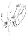
- a buffer device for converting the energy produced on a road receives the energy (static, kinetic energy of the rolling wheel) delivered by a vehicle 100 and even pedestrians when being weighed down on a pressure chamber 210 formed in a compression unit.
- the fluid contained in the pressure chamber 210 is pressurized to output a kinetic energy and at the same time, alleviating the vibration of the vehicle 100.
- a compression unit 200 is installed beneath the road surface 150.
- the fluid in the pressure chamber 210 is pressurized to store the static energy and then conducted to pass through a check valve 250 to flow in one direction, and the vibration of the vehicle is also alleviated by the cushion effect of the restoring force of the compression unit 200 performed by a restorable elastic element 218.
- the restorable elastic element 218 is a spring, or replaceable with the fluid in the pressure chamber 210.
- the fluid to be used is essentially air.
- a fluid conduit 260 is connected behind the check valve 250 to conduct the pressurized fluid to pass through in one direction along the fluid conduit 260 so as to make use of its kinetic energy.
- a governor valve 300 is provided to the exit of the fluid conduit 260 so as to control discharge of the fluid.
- the pressurized fluid discharged from the fluid conduit 260 is used to drive a vane wheel 400 (windmill, watermill) or a water spray gun by releasing its static energy.
- a generator 500 is connected to the vane wheel 400 or a water spray gun to be driven to generate electric energy.
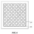
- the pressure receiver plate 220 has a structure of a large square plate whose surface contains a number of small square grid shaped meshes, or is patterned in a beehive configuration 215. After being liberated from the weight of the vehicle 100 or the pedestrian, the pressure receiver plate 220 recovers its initial state with the aid of the restorable elastic element 218 and ready for successively coming vehicles 100 or pedestrians to weigh down.
Landscapes
- Engineering & Computer Science (AREA)
- Chemical & Material Sciences (AREA)
- Combustion & Propulsion (AREA)
- Mechanical Engineering (AREA)
- General Engineering & Computer Science (AREA)
- Wind Motors (AREA)
Applications Claiming Priority (1)
| Application Number | Priority Date | Filing Date | Title |
|---|---|---|---|
| PCT/CN2008/072262 WO2010025592A1 (fr) | 2008-09-04 | 2008-09-04 | Dispositif tampon destiné à convertir l'énergie produite sur une route |
Publications (2)
| Publication Number | Publication Date |
|---|---|
| EP2336562A1 true EP2336562A1 (fr) | 2011-06-22 |
| EP2336562A4 EP2336562A4 (fr) | 2012-02-15 |
Family
ID=41796712
Family Applications (1)
| Application Number | Title | Priority Date | Filing Date |
|---|---|---|---|
| EP08800774A Withdrawn EP2336562A4 (fr) | 2008-09-04 | 2008-09-04 | Dispositif tampon destiné à convertir l'énergie produite sur une route |
Country Status (3)
| Country | Link |
|---|---|
| EP (1) | EP2336562A4 (fr) |
| IL (1) | IL211590A0 (fr) |
| WO (1) | WO2010025592A1 (fr) |
Families Citing this family (1)
| Publication number | Priority date | Publication date | Assignee | Title |
|---|---|---|---|---|
| CN101882888B (zh) * | 2010-07-16 | 2012-08-29 | 华北电力大学(保定) | 一种车流碾压发电装置 |
Family Cites Families (9)
| Publication number | Priority date | Publication date | Assignee | Title |
|---|---|---|---|---|
| US4173431A (en) * | 1977-07-11 | 1979-11-06 | Nu-Watt, Inc. | Road vehicle-actuated air compressor and system therefor |
| JPS57105571A (en) * | 1980-12-22 | 1982-07-01 | Mitsutoyo Mfg Co Ltd | Method and device for power generation |
| JPS57137658A (en) * | 1981-02-18 | 1982-08-25 | Takamisawa Saibaneteitsukusu:Kk | Road power generation method |
| US4739179A (en) * | 1987-03-17 | 1988-04-19 | Stites Howard A | System for generating power by vehicle movement and methods of constructing and utilizing same |
| JP2001032764A (ja) * | 1999-07-22 | 2001-02-06 | Mitsubishi Electric Corp | エネルギ回収装置 |
| JP2001153030A (ja) * | 1999-11-29 | 2001-06-05 | Kazumi Maekawa | 車の重力エネルギーを連続利用して行う発電装置 |
| JP2004324628A (ja) * | 2003-04-25 | 2004-11-18 | Akira Uchiyama | 車両重量による発電システム |
| CN2921354Y (zh) * | 2006-05-26 | 2007-07-11 | 冯超 | 公路车辆滚压力的能量转化利用装置 |
| TWM316933U (en) * | 2006-10-30 | 2007-08-11 | Hung-Wei Jang | Multi-function and energy-storing road generator |
-
2008
- 2008-09-04 WO PCT/CN2008/072262 patent/WO2010025592A1/fr not_active Ceased
- 2008-09-04 EP EP08800774A patent/EP2336562A4/fr not_active Withdrawn
-
2011
- 2011-03-06 IL IL211590A patent/IL211590A0/en unknown
Also Published As
| Publication number | Publication date |
|---|---|
| IL211590A0 (en) | 2011-05-31 |
| WO2010025592A1 (fr) | 2010-03-11 |
| EP2336562A4 (fr) | 2012-02-15 |
Similar Documents
| Publication | Publication Date | Title |
|---|---|---|
| US20100072758A1 (en) | On-Road Energy Conversion and Vibration Absorber Apparatus | |
| EP2710262B1 (fr) | Appareil d'absorption de vibrations et de conversion d'énergie produite sur une chaussée | |
| GB2461860A (en) | Driving an electricity generator using the kinetic, gravitational or air pressure forces present in the flow of vehicular or pedestrian traffic or sea waves | |
| GB2450334A (en) | Vehicle power unit | |
| KR20090055536A (ko) | 물체의 무게 중력에 의한 유 압력 구동 발전기 | |
| KR20120071215A (ko) | 도로 상 요철을 이용한 발전장치 | |
| CN201258836Y (zh) | 道路能量转换缓冲装置 | |
| CN205445969U (zh) | 人造风能发电机 | |
| JP2001248538A (ja) | ゼンマイを利用した、蓄えられるエネルギー装置 | |
| KR20230081834A (ko) | 신재생 에너지 장치를 구비한 전동 킥보드 | |
| KR102070808B1 (ko) | 중압 발전 시스템 및 이를 이용한 발전 방법 | |
| NZ618685B2 (en) | On-road energy conversion and vibration absorber apparatus | |
| OA16659A (en) | On-road energy conversion and vibration absorber apparatus. | |
| JPS57105571A (en) | Method and device for power generation | |
| MY209664A (en) | Air-compression energy-storage and power-supply system having air purification capability through using solar energy | |
| JP3146592U (ja) | 路上エネルギーの転換減震装置 | |
| JPH06213137A (ja) | 車重発電装置 | |
| HK1194452B (en) | On-road energy conversion and vibration absorber apparatus | |
| WO2010025592A1 (fr) | Dispositif tampon destiné à convertir l'énergie produite sur une route | |
| CN104879260A (zh) | 一种高效节水的水力发电装置 | |
| TW201243149A (en) | High efficiency wave energy green environmental protection power generation system | |
| JPS5718467A (en) | Electric power generator actuated by compressed air produced by seasaw action | |
| KR20060022846A (ko) | 자동차 도로 발전기 | |
| TW201002545A (en) | Road energy conversion and cushioning device | |
| JP2005069213A (ja) | 潜在圧力応用発動機 |
Legal Events
| Date | Code | Title | Description |
|---|---|---|---|
| PUAI | Public reference made under article 153(3) epc to a published international application that has entered the european phase |
Free format text: ORIGINAL CODE: 0009012 |
|
| 17P | Request for examination filed |
Effective date: 20110404 |
|
| AK | Designated contracting states |
Kind code of ref document: A1 Designated state(s): AT BE BG CH CY CZ DE DK EE ES FI FR GB GR HR HU IE IS IT LI LT LU LV MC MT NL NO PL PT RO SE SI SK TR |
|
| AX | Request for extension of the european patent |
Extension state: AL BA MK RS |
|
| DAX | Request for extension of the european patent (deleted) | ||
| A4 | Supplementary search report drawn up and despatched |
Effective date: 20120118 |
|
| RIC1 | Information provided on ipc code assigned before grant |
Ipc: F03G 3/00 20060101AFI20120112BHEP Ipc: F03G 7/08 20060101ALI20120112BHEP |
|
| STAA | Information on the status of an ep patent application or granted ep patent |
Free format text: STATUS: THE APPLICATION IS DEEMED TO BE WITHDRAWN |
|
| 18D | Application deemed to be withdrawn |
Effective date: 20170401 |