EP2336607A1 - Scheibenbremse, insbesondere für ein Nutzfahrzeug - Google Patents
Scheibenbremse, insbesondere für ein Nutzfahrzeug Download PDFInfo
- Publication number
- EP2336607A1 EP2336607A1 EP10195117A EP10195117A EP2336607A1 EP 2336607 A1 EP2336607 A1 EP 2336607A1 EP 10195117 A EP10195117 A EP 10195117A EP 10195117 A EP10195117 A EP 10195117A EP 2336607 A1 EP2336607 A1 EP 2336607A1
- Authority
- EP
- European Patent Office
- Prior art keywords
- bellows
- brake
- disc brake
- disc
- spindle
- Prior art date
- Legal status (The legal status is an assumption and is not a legal conclusion. Google has not performed a legal analysis and makes no representation as to the accuracy of the status listed.)
- Granted
Links
- 238000007789 sealing Methods 0.000 claims abstract description 4
- 210000002105 tongue Anatomy 0.000 claims description 9
- 238000003780 insertion Methods 0.000 claims description 4
- 230000037431 insertion Effects 0.000 claims description 4
- 238000004519 manufacturing process Methods 0.000 description 4
- 230000000694 effects Effects 0.000 description 2
- 239000000463 material Substances 0.000 description 2
- 230000007797 corrosion Effects 0.000 description 1
- 238000005260 corrosion Methods 0.000 description 1
- 229920001971 elastomer Polymers 0.000 description 1
- 239000000806 elastomer Substances 0.000 description 1
- 239000013536 elastomeric material Substances 0.000 description 1
- 238000009434 installation Methods 0.000 description 1
- 239000002184 metal Substances 0.000 description 1
- 238000000465 moulding Methods 0.000 description 1
- 238000005457 optimization Methods 0.000 description 1
- 230000002093 peripheral effect Effects 0.000 description 1
- 238000004080 punching Methods 0.000 description 1
- 230000000087 stabilizing effect Effects 0.000 description 1
Images
Classifications
-
- F—MECHANICAL ENGINEERING; LIGHTING; HEATING; WEAPONS; BLASTING
- F16—ENGINEERING ELEMENTS AND UNITS; GENERAL MEASURES FOR PRODUCING AND MAINTAINING EFFECTIVE FUNCTIONING OF MACHINES OR INSTALLATIONS; THERMAL INSULATION IN GENERAL
- F16D—COUPLINGS FOR TRANSMITTING ROTATION; CLUTCHES; BRAKES
- F16D65/00—Parts or details
- F16D65/14—Actuating mechanisms for brakes; Means for initiating operation at a predetermined position
- F16D65/16—Actuating mechanisms for brakes; Means for initiating operation at a predetermined position arranged in or on the brake
- F16D65/18—Actuating mechanisms for brakes; Means for initiating operation at a predetermined position arranged in or on the brake adapted for drawing members together, e.g. for disc brakes
- F16D65/183—Actuating mechanisms for brakes; Means for initiating operation at a predetermined position arranged in or on the brake adapted for drawing members together, e.g. for disc brakes with force-transmitting members arranged side by side acting on a spot type force-applying member
-
- F—MECHANICAL ENGINEERING; LIGHTING; HEATING; WEAPONS; BLASTING
- F16—ENGINEERING ELEMENTS AND UNITS; GENERAL MEASURES FOR PRODUCING AND MAINTAINING EFFECTIVE FUNCTIONING OF MACHINES OR INSTALLATIONS; THERMAL INSULATION IN GENERAL
- F16J—PISTONS; CYLINDERS; SEALINGS
- F16J3/00—Diaphragms; Bellows; Bellows pistons
- F16J3/04—Bellows
- F16J3/041—Non-metallic bellows
-
- F—MECHANICAL ENGINEERING; LIGHTING; HEATING; WEAPONS; BLASTING
- F16—ENGINEERING ELEMENTS AND UNITS; GENERAL MEASURES FOR PRODUCING AND MAINTAINING EFFECTIVE FUNCTIONING OF MACHINES OR INSTALLATIONS; THERMAL INSULATION IN GENERAL
- F16J—PISTONS; CYLINDERS; SEALINGS
- F16J3/00—Diaphragms; Bellows; Bellows pistons
- F16J3/04—Bellows
- F16J3/041—Non-metallic bellows
- F16J3/042—Fastening details
-
- F—MECHANICAL ENGINEERING; LIGHTING; HEATING; WEAPONS; BLASTING
- F16—ENGINEERING ELEMENTS AND UNITS; GENERAL MEASURES FOR PRODUCING AND MAINTAINING EFFECTIVE FUNCTIONING OF MACHINES OR INSTALLATIONS; THERMAL INSULATION IN GENERAL
- F16D—COUPLINGS FOR TRANSMITTING ROTATION; CLUTCHES; BRAKES
- F16D2121/00—Type of actuator operation force
- F16D2121/14—Mechanical
-
- F—MECHANICAL ENGINEERING; LIGHTING; HEATING; WEAPONS; BLASTING
- F16—ENGINEERING ELEMENTS AND UNITS; GENERAL MEASURES FOR PRODUCING AND MAINTAINING EFFECTIVE FUNCTIONING OF MACHINES OR INSTALLATIONS; THERMAL INSULATION IN GENERAL
- F16D—COUPLINGS FOR TRANSMITTING ROTATION; CLUTCHES; BRAKES
- F16D2125/00—Components of actuators
- F16D2125/18—Mechanical mechanisms
- F16D2125/58—Mechanical mechanisms transmitting linear movement
- F16D2125/70—Rods
Definitions
- the invention relates to a disk brake, in particular for a commercial vehicle, according to the preamble of claim 1.
- this receiving space is largely closed, on the application side associated with a brake caliper brake lining side by means of a closure lid.
- the adjusting spindles which can be pressed against the brake lining by means of the application device, are guided through the closure lid and sealed here in each case by means of a bellows, which is fastened on the adjusting spindle on one side and on the closure cover on the other side.
- the closure lid has a collar which peripherally delimits the passage opening of the adjusting spindle, on the inside of which an end region of the bellows rests frictionally.
- the closure lid of an elastic, ie deformable Material is, in the connection region with the closure lid in the adjacent end region of the bellows a stable, usually metallic insert incorporated, preferably by molding, when the bellows is made entirely of plastic.
- the invention has for its object to further develop a disc brake of the generic type so that their reliability improves, increases the service life and the manufacturing cost can be reduced.
- the improved functional or operational reliability ultimately leads to an optimization of operating costs, or at least to a reduction in operating costs.
- the cost reduction also contributes that the invention is very easy to implement.
- the bellows remain unchanged while, as provided according to an advantageous embodiment of the invention, can be punched into the collar locking tongues, which protrude to the contact surface to the bellows and engage in the existing elastomeric material of the bellows such that a form-fitting Fuse is achieved in each direction.
- the closure lid usually consists of a sheet-metal stamped part, so that the introduction of the locking tongues takes place without additional expenditure when punching the closure lid.
- the positive locking means are designed so that they are formed counter to the direction of insertion of the bellows in the passage opening for the adjusting spindle in the sense of a barb, so that while the insertion is easy, but not pulling out at all possible, at least not without the bellows in the Destroying investment area.
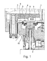
- FIG. 1 is a half of a disc brake shown, which has formed as a sliding caliper caliper 1, which includes a brake disc 3 in its upper peripheral region.
- the disc brake can be operated pneumatically or by electric motor.
- brake pads 4 are arranged, of which an action-side is shown here, which can be pressed against the brake disc 3 in the case of operation.
- the brake pad 4 consists of a support plate 6, one on the brake disc 3 facing side attached friction lining 8 and two fixedly connected to the support plate 6 pressure pieces 5, one of which in the FIG. 1 is recognizable.
- An adjusting spindle 10 which is arranged in the caliper 1 and can be actuated via a rotary lever, presses an adjusting spindle 10 against the pressure piece 5 and thus against the brake pad 4.
- the pressure piece can also be arranged on the end face of the adjusting spindle 10.
- the brake caliper 1 is largely closed on its side facing the brake disk 3 by a closure cover 7 which is perforated in the outlet region of the adjusting spindle 10.
- a bellows 9 connected to the closing cover 7 is provided, which is, on the other hand, fastened to the adjusting spindle 10.
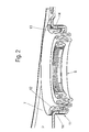
- the bellows 9 is positively connected to the closure lid 7, to which, as particularly clear in the FIG. 2 it can be seen, the closure cover 7 has positive locking means in the form of locking tongues 14.
- These locking tongues 14 are in a the exit region of the adjusting spindle 10, on the representation in the FIG. 2 is omitted, stamped limiting circumferential collar 11 and extend, slightly angled into the interior of the outlet region in such a way that they act against the bellows 9 against the insertion direction in the sense of a barb. That is, the locking tongues 14 dig when inserting the bellows 9 in the exit region in the one stabilizing ring 12 enclosing material 13 of the bellows 9, which consists of a plastic, preferably an elastomer.
- the outer diameter of the bellows 9 in the contact area on the inner surface of the collar 11 corresponds approximately to its clear diameter, without, however, having to comply with particularly tight tolerances.
- the bellows 9 is provided with an angled edge which forms a stop when inserted into the outlet region of the closure lid by abutment thereon.
- the latching means here the latching tongues 14, are distributed over the circumference of the collar 11, preferably at equal angular intervals.
Landscapes
- Engineering & Computer Science (AREA)
- General Engineering & Computer Science (AREA)
- Mechanical Engineering (AREA)
- Sealing Devices (AREA)
- Braking Arrangements (AREA)
Abstract
Description
- Die Erfindung betrifft eine Scheibenbremse insbesondere für ein Nutzfahrzeug, nach dem Oberbegriff des Anspruchs 1.
- Um die in einem Aufnahmeraum des Bremssattels angeordneten funktionsrelevanten Bauteile, wie eine Zuspanneinrichtung, vor Korrosion durch Witterungseinflüsse zu schützen, ist dieser Aufnahmeraum weitgehend verschlossen, und zwar auf der dem bei einer Schiebesattelbremse zuspannseitigen Bremsbelag zugeordneten Seite mittels eines Verschlussdeckels.
- Die Stellspindeln, die mittels der Zuspanneinrichtung gegen den Bremsbelag drückbar sind, sind durch den Verschlussdeckel geführt und hier jeweils mittels eines Faltenbalgs abgedichtet, der einerseits an der Stellspindel und andererseits an dem Verschlussdeckel befestigt ist.
- Hierzu weist der Verschlussdeckel einen die Durchtrittsöffnung der Stellspindel umfänglich begrenzenden Kragen auf, an dessen Innenseite ein Endbereich des Faltenbalgs reibschlüssig anliegt.
- Um diesen Reibschluss herstellen zu können, sind jedoch bestimmte Voraussetzungen zu erfüllen. Hierzu zählen insbesondere sehr enge Toleranzen, vor allem des lichten Durchmessers des Kragens sowie dessen Oberflächenbeschaffenheit, aber auch eine genau runde Außenkontur des Faltenbalges im Verbindungsbereich mit dem Verschlussdeckel. Nur so ist ein halbwegs sicherer Presssitz zu erreichen.
- Da der Faltenbalg insgesamt aufgrund der Relativbewegung der Stellspindel, an der der Faltenbalg andererseits befestigt ist, bzw. eines mit der Stellspindel fest verbundenen Druckstücks, zum Verschlussdeckel aus einem elastischen, d.h. deformierbaren Material besteht, ist im Verbindungsbereich mit dem Verschlussdeckel in den anliegenden Endbereich des Faltenbalgs eine stabile, üblicherweise metallische Einlage eingearbeitet, bevorzugt durch Umspritzen, wenn der Faltenbalg insgesamt aus Kunststoff hergestellt ist.
- Trotz des notwendigerweise betriebenen Aufwands hinsichtlich der genannten engen Durchmessertoleranzen, der Oberflächenbeschaffenheit der Anlageseite des Kragens, sowie der genau runden Kontur des Faltenbalges, besteht die Gefahr, dass der Faltenbalg durch die Relativbewegung des an der Stellspindel befestigten Endes zum am Verschlussdeckel angebrachten Endbereichs des Faltenbalgs die reibschlüssige Verbindung so weit gelöst wird, dass er aus dem Kragen herauswandert, so dass eine dauerhaft angestrebte Dichtwirkung nicht gewährleistet ist.
- Daneben sind in der Folge der erforderlichen engen Toleranzen entsprechend aufwendige Fertigungsmaßnahmen erforderlich, die zu relativ hohen Fertigungskosten insgesamt führen.
- Der Erfindung liegt die Aufgabe zugrunde, eine Scheibenbremse der gattungsgemäßen Art so weiterzuentwickeln, dass ihre Betriebssicherheit verbessert, die Standzeit erhöht und die Fertigungskosten reduziert werden.
- Diese Aufgabe wird durch eine Scheibenbremse mit den Merkmalen des Anspruchs 1 gelöst.
- Durch diese konstruktive Ausbildung werden eine ganze Reihe von Vorteilen gegenüber dem Stand der Technik erreicht.
- So ist zunächst der verbesserte Halt des Faltenbalgs im Verschlussdeckel zu nennen, der dazu führt, dass ein Verrutschen oder gar Lösen des Faltenbalges aus seinem Sitz mit dem Verschlussdeckel ausgeschlossen ist.
- Naturgemäß erhöht dies die Betriebssicherheit ebenso wie die Standzeit der Scheibenbremse, da der Aufnahmeraum dauerhaft, also über die gesamte Betriebszeit der Scheibenbremse abgedichtet ist, so dass weder Schmutz noch Feuchtigkeit in den Aufnahmeraum dringen können, was die darin befindlichen Funktionsteile in Mitleidenschaft ziehen würde.
- Die verbesserte Funktions- bzw. Betriebssicherheit führt letztendlich zu einer Betriebskostenoptimierung, zumindest aber zu einer Betriebskostenreduzierung.
- Darüber hinaus ergeben sich durch die Erfindung verminderte Fertigungskosten, da weder für den Faltenbalg im Anbindungsbereich am Verschlussdeckel, noch an der zugeordneten Anlagefläche des Kragens besonders enge Toleranzen eingehalten werden müssen bzw. der Faltenbalg durchaus in gewissem Maße unrund sein kann.
- Zu der Kostenreduzierung trägt auch bei, dass die Erfindung sehr einfach zu realisieren ist. So kann der Faltenbalg unverändert bleiben, während, wie nach einer vorteilhaften Weiterbildung der Erfindung vorgesehen, in den Kragen Rastzungen eingestanzt sein können, die an der Anlagefläche zum Faltenbalg vorstehen und die in das aus einem Elastomer bestehende Material des Faltenbalges derart eingreifen, dass eine formschlüssige Sicherung in jeder Richtung erreicht wird.
- Der Verschlussdeckel besteht üblicherweise aus einem Blech-Stanzteil, so dass das Einbringen der Rastzungen ohne Mehraufwand beim Stanzen des Verschlussdeckels erfolgt.
- Daneben bleibt dieser in seiner übrigen Konfiguration unverändert, so dass im Servicefall, wenn beispielsweise Bremsbeläge ausgetauscht werden müssen, auch der vorhandene gegen einen neuen Verschlussdeckel getauscht werden kann, ohne dass es dazu besonderer Montagearbeiten erfordert. So kann der Faltenbalg mit seinem dem Kragen zugeordneten Endbereich in die lichte Durchtrittsöffnung für die Stellspindel eingedrückt werden mit sofortiger Wirkung des Formschlusses.
- Neben den genannten Rastzungen sind selbstverständlich auch andere Formschlussmittel möglich, die in den Faltenbalg radial eingreifen, beispielsweise in Form von geprägten, vorstehenden Noppen, Spitzen oder dergleichen. Zweckmäßig sind die Formschlussmittel so gestaltet, dass sie entgegen der Einschubrichtung des Faltenbalges in die Durchtrittsöffnung für die Stellspindel im Sinne eines Widerhakens ausgebildet sind, so dass zwar das Einschieben leicht, nicht jedoch das Herausziehen überhaupt möglich ist, zumindest nicht, ohne den Faltenbalg in dem Anlagebereich zu zerstören.
- Weitere vorteilhafte Ausbildungen der Erfindung sind in den Unteransprüchen gekennzeichnet.
- Ein Ausführungsbeispiel der Erfindung wird nachfolgend anhand der beigefügten Zeichnungen beschrieben.
- Es zeigen:
- Figur 1
- einen Teilausschnitt einer Scheibenbremse in einer geschnittenen Draufsicht
- Figur 2
- eine Einzelheit der Scheibenbremse in einer geschnittenen perspek-tivischen Seitenansicht.
- In der
Figur 1 ist eine Hälfte einer Scheibenbremse dargestellt, die einen als Schiebesattel ausgebildeten Bremssattel 1 aufweist, der eine Bremsscheibe 3 in ihrem oberen Umfangsbereich umfasst. Dabei kann die Scheibenbremse pneumatisch oder elektromotorisch betätigbar sein. - Zu beiden Seiten der Bremsscheibe 3 sind Bremsbeläge 4 angeordnet, von denen hier ein aktionsseitiger dargestellt ist, der im Funktionsfall gegen die Bremsscheibe 3 pressbar ist.
- Der Bremsbelag 4 besteht aus einer Trägerplatte 6, einem auf deren der Bremsscheibe 3 zugewandten Seite befestigten Reibbelag 8 sowie zwei fest mit der Trägerplatte 6 verbundenen Druckstücken 5, von denen eines in der
Figur 1 erkennbar ist. - Über eine im Bremssattel 1 angeordnete, über einen Drehhebel betätigbare Zuspanneinrichtung 2 wird eine Stellspindel 10 gegen das Druckstück 5 und damit gegen den Bremsbelag 4 gedrückt. Anstelle des fest mit der Trägerplatte 6 verbundenen Druckstücks 5 kann das Druckstück auch an der Stirnseite der Stellspindel 10 angeordnet sein.
- Zur Einstellung eines Lüftspiels zwischen dem Reibbelag 8 und der Bremsscheibe 3, unter Berücksichtigung des Verschleißes des Reibbelages 8, ist die als Gewindespindel ausgebildete Stellspindel 10 drehbar im Bremssattel gelagert und über eine nicht dargestellte Nachstelleinrichtung bewegbar.
- Der Bremssattel 1 ist auf seiner der Bremsscheibe 3 zugewandten Seite weitgehend durch einen Verschlussdeckel 7 verschlossen, der im Austrittsbereich der Stellspindel 10 durchbrochen ist.
- Zur Abdichtung des Austrittsbereichs der Stellspindel 10 aus dem Bremssattel 1 ist ein mit dem Verschlussdeckel 7 verbundener Faltenbalg 9 vorgesehen, der anderseits an der Stellspindel 10 befestigt ist.
- Erfindungsgemäß ist der Faltenbalg 9 formschlüssig am Verschlussdeckel 7 angeschlossen, wozu, wie besonders deutlich in der
Figur 2 zu erkennen ist, der Verschlussdeckel 7 Formschlussmittel in Form von Rastzungen 14 aufweist. - Diese Rastzungen 14 sind in einen den Austrittsbereich der Stellspindel 10, auf deren Darstellung in der
Figur 2 verzichtet ist, begrenzenden umlaufenden Kragen 11 eingestanzt und erstrecken sich, geringfügig abgewinkelt in den Innenraum des Austrittsbereichs und zwar derart, dass sie gegenüber dem Faltenbalg 9 entgegen der Einschieberichtung im Sinne eines Widerhakens fungieren. D.h., die Rastzungen 14 graben sich beim Einschieben des Faltenbalges 9 in den Austrittsbereich in das einen Stabilisierungsring 12 umhüllende Material 13 des Faltenbalges 9, das aus einem Kunststoff, vorzugsweise einem Elastomer besteht. - Dabei entspricht der Außendurchmesser des Faltenbalgs 9 im Anlagebereich an der Innenfläche des Kragens 11 etwa dessen lichtem Durchmesser, ohne dass jedoch besonders enge Toleranzen eingehalten werden müssen.
- Im Übrigen ist der Faltenbalg 9 mit einem abgewinkelten Rand versehen, der beim Einschieben in den Austrittsbereich des Verschlussdeckels durch Anlage an diesen einen Anschlag bildet.
- Bevorzugt sind die Rastmittel, hier die Rastzungen 14, über den Umfang des Kragens 11 verteilt angeordnet, vorzugsweise in gleichen Winkelabständen.
Claims (7)
- Scheibenbremse, mit einem Bremssattel (1), in dem zwei in Funktion gegen eine Bremsscheibe (3) pressbare Bremsbeläge (4) angeordnet sind, von denen ein aktionsseitiger über mindestens eine Stellspindel (10) mittels einer Zuspanneinrichtung betätigbar ist, wobei die Stellspindel (10) durch einen einen Aufnahmeraum (2) des Bremssattels (1) zur Bremsscheibe (3) hin verschließenden Verschlussdeckel (7) geführt ist, an dem zur Abdichtung ein andererseits an der Stellspindel (10) befestigter Faltenbalg (9) angeschlossen ist, dadurch gekennzeichnet, dass der Faltenbalg (9) formschlüssig am Verschlussdeckel (7) befestigt ist.
- Scheibenbremse nach Anspruch 1, dadurch gekennzeichnet, dass der Verschlussdeckel (7) im Durchtrittsbereich der Stellspindel (10) einen abgewinkelten Kragen (11) aufweist, in den Formschlussmittel eingebracht sind, die in den Faltenbalg (9) eingreifen.
- Scheibenbremse nach Anspruch 1 oder 2, dadurch gekennzeichnet, dass die Formschlussmittel eingestanzt sind.
- Scheibenbremse nach einem der vorhergehenden Ansprüche, dadurch gekennzeichnet, dass die Formschlussmittel aus Rastzungen (14), Noppen oder dergleichen bestehen.
- Scheibenbremse nach einem der vorhergehenden Ansprüche, dadurch gekennzeichnet, dass die Rastzungen (14) in Einschieberichtung des Faltenbalges (9) im Sinne eines Widerhakens abgewinkelt verlaufen.
- Scheibenbremse nach einem der vorhergehenden Ansprüche, dadurch gekennzeichnet, dass die Rastmittel über den Umfang des Kragens (11) verteilt angeordnet sind.
- Scheibenbremse nach einem der vorhergehenden Ansprüche, dadurch gekennzeichnet, dass die Rastmittel in gleichen Winkelabständen zueinander angeordnet sind.
Applications Claiming Priority (1)
| Application Number | Priority Date | Filing Date | Title |
|---|---|---|---|
| DE200910059818 DE102009059818A1 (de) | 2009-12-21 | 2009-12-21 | Scheibenbremse, insbesondere für ein Nutzfahrzeug |
Publications (2)
| Publication Number | Publication Date |
|---|---|
| EP2336607A1 true EP2336607A1 (de) | 2011-06-22 |
| EP2336607B1 EP2336607B1 (de) | 2012-10-10 |
Family
ID=43629636
Family Applications (1)
| Application Number | Title | Priority Date | Filing Date |
|---|---|---|---|
| EP20100195117 Not-in-force EP2336607B1 (de) | 2009-12-21 | 2010-12-15 | Scheibenbremse, insbesondere für ein Nutzfahrzeug |
Country Status (2)
| Country | Link |
|---|---|
| EP (1) | EP2336607B1 (de) |
| DE (1) | DE102009059818A1 (de) |
Cited By (2)
| Publication number | Priority date | Publication date | Assignee | Title |
|---|---|---|---|---|
| EP2412997A1 (de) * | 2010-07-28 | 2012-02-01 | KNORR-BREMSE Systeme für Nutzfahrzeuge GmbH | Scheibenbremse |
| CN109563895A (zh) * | 2016-06-16 | 2019-04-02 | 克诺尔商用车制动系统有限公司 | 用于商用车的盘式制动器 |
Citations (4)
| Publication number | Priority date | Publication date | Assignee | Title |
|---|---|---|---|---|
| WO1996034216A1 (de) * | 1995-04-27 | 1996-10-31 | Knorr-Bremse Systeme für Nutzfahrzeuge GmbH | Scheibenbremse für fahrzeuge, insbesondere strassenfahrzeuge |
| US20010047913A1 (en) * | 2000-05-24 | 2001-12-06 | Roberto Conti | Disk brake actuator |
| WO2008025489A1 (de) * | 2006-08-31 | 2008-03-06 | Knorr-Bremse Systeme für Nutzfahrzeuge GmbH | Scheibenbremse, insbesondere für ein nutzfahrzeug |
| EP2199639A2 (de) * | 2008-12-19 | 2010-06-23 | KNORR-BREMSE Systeme für Nutzfahrzeuge GmbH | Scheibenbremse für ein Nutzfahrzeug |
Family Cites Families (4)
| Publication number | Priority date | Publication date | Assignee | Title |
|---|---|---|---|---|
| US4508018A (en) * | 1983-07-11 | 1985-04-02 | Thyssen-Bornemisza, Inc. | Boot assembly for brake actuator |
| DE10330633A1 (de) * | 2003-05-19 | 2004-12-16 | Knorr-Bremse Systeme für Nutzfahrzeuge GmbH | Pneumatisch oder elektromotorisch betätigbare Scheibenbremse |
| DE102005035583B4 (de) * | 2005-07-29 | 2016-12-29 | Bpw Bergische Achsen Kg | Scheibenbremse |
| DE102006050519B4 (de) * | 2006-10-26 | 2008-06-12 | Knorr-Bremse Systeme für Nutzfahrzeuge GmbH | Scheibenbremse für ein Nutzfahrzeug |
-
2009
- 2009-12-21 DE DE200910059818 patent/DE102009059818A1/de not_active Ceased
-
2010
- 2010-12-15 EP EP20100195117 patent/EP2336607B1/de not_active Not-in-force
Patent Citations (4)
| Publication number | Priority date | Publication date | Assignee | Title |
|---|---|---|---|---|
| WO1996034216A1 (de) * | 1995-04-27 | 1996-10-31 | Knorr-Bremse Systeme für Nutzfahrzeuge GmbH | Scheibenbremse für fahrzeuge, insbesondere strassenfahrzeuge |
| US20010047913A1 (en) * | 2000-05-24 | 2001-12-06 | Roberto Conti | Disk brake actuator |
| WO2008025489A1 (de) * | 2006-08-31 | 2008-03-06 | Knorr-Bremse Systeme für Nutzfahrzeuge GmbH | Scheibenbremse, insbesondere für ein nutzfahrzeug |
| EP2199639A2 (de) * | 2008-12-19 | 2010-06-23 | KNORR-BREMSE Systeme für Nutzfahrzeuge GmbH | Scheibenbremse für ein Nutzfahrzeug |
Cited By (2)
| Publication number | Priority date | Publication date | Assignee | Title |
|---|---|---|---|---|
| EP2412997A1 (de) * | 2010-07-28 | 2012-02-01 | KNORR-BREMSE Systeme für Nutzfahrzeuge GmbH | Scheibenbremse |
| CN109563895A (zh) * | 2016-06-16 | 2019-04-02 | 克诺尔商用车制动系统有限公司 | 用于商用车的盘式制动器 |
Also Published As
| Publication number | Publication date |
|---|---|
| EP2336607B1 (de) | 2012-10-10 |
| DE102009059818A1 (de) | 2011-06-22 |
Similar Documents
| Publication | Publication Date | Title |
|---|---|---|
| EP2489897B1 (de) | Scheibenbremse | |
| EP2199639B1 (de) | Scheibenbremse für ein Nutzfahrzeug | |
| DE102015105344A1 (de) | Scheibenbremse für ein Nutzfahrzeug | |
| EP1982086B1 (de) | Scheibenbremse, insbesondere für ein nutzfahrzeug | |
| DE102013006859B4 (de) | Scheibenbremse für ein Nutzfahrzeug | |
| EP2444698B1 (de) | Scheibenbremse | |
| EP2520820B1 (de) | Scheibenbremse, insbesondere für ein Nutzfahrzeug | |
| EP1916438B1 (de) | Scheibenbremse für ein Nutzfahrzeug | |
| EP2877754A1 (de) | Scheibenbremse für ein nutzfahrzeug | |
| EP2943697B1 (de) | Scheibenbremse für ein nutzfahrzeug | |
| EP2336607B1 (de) | Scheibenbremse, insbesondere für ein Nutzfahrzeug | |
| EP2469118B1 (de) | Scheibenbremse | |
| EP2412997B1 (de) | Scheibenbremse | |
| EP1209404A1 (de) | Anschlussvorrichtung für eine Fluidleitung | |
| EP2354585B1 (de) | Scheibenbremse, insbesondere für ein Nutzfahrzeug | |
| EP3482098A2 (de) | Scheibenbremse für ein nutzfahrzeug | |
| EP3589867B1 (de) | Faltenbalg sowie mindestens einen faltenbalg aufweisende scheibenbremse | |
| DE102010045566A1 (de) | Scheibenbremse mit einer Dichtungseinrichtung | |
| EP2895759B1 (de) | Scheibenbremse für ein nutzfahrzeug | |
| WO2018024712A1 (de) | Scheibenbremse für ein nutzfahrzeug | |
| EP1841981B1 (de) | Scheibenbremse | |
| DE102005054402B4 (de) | Scheibenbremse, insbesondere für ein Nutzfahrzeug | |
| EP2948692B1 (de) | Scheibenbremse für ein nutzfahrzeug | |
| EP2363617A1 (de) | Scheibenbremse für ein Nutzfahrzeug | |
| DE102009049062B4 (de) | Scheibenbremse für ein Nutzfahrzeug |
Legal Events
| Date | Code | Title | Description |
|---|---|---|---|
| PUAI | Public reference made under article 153(3) epc to a published international application that has entered the european phase |
Free format text: ORIGINAL CODE: 0009012 |
|
| AK | Designated contracting states |
Kind code of ref document: A1 Designated state(s): AL AT BE BG CH CY CZ DE DK EE ES FI FR GB GR HR HU IE IS IT LI LT LU LV MC MK MT NL NO PL PT RO RS SE SI SK SM TR |
|
| AX | Request for extension of the european patent |
Extension state: BA ME |
|
| 17P | Request for examination filed |
Effective date: 20111222 |
|
| GRAP | Despatch of communication of intention to grant a patent |
Free format text: ORIGINAL CODE: EPIDOSNIGR1 |
|
| GRAS | Grant fee paid |
Free format text: ORIGINAL CODE: EPIDOSNIGR3 |
|
| GRAA | (expected) grant |
Free format text: ORIGINAL CODE: 0009210 |
|
| AK | Designated contracting states |
Kind code of ref document: B1 Designated state(s): AL AT BE BG CH CY CZ DE DK EE ES FI FR GB GR HR HU IE IS IT LI LT LU LV MC MK MT NL NO PL PT RO RS SE SI SK SM TR |
|
| REG | Reference to a national code |
Ref country code: GB Ref legal event code: FG4D Free format text: NOT ENGLISH |
|
| REG | Reference to a national code |
Ref country code: AT Ref legal event code: REF Ref document number: 579117 Country of ref document: AT Kind code of ref document: T Effective date: 20121015 Ref country code: CH Ref legal event code: EP |
|
| REG | Reference to a national code |
Ref country code: IE Ref legal event code: FG4D Free format text: LANGUAGE OF EP DOCUMENT: GERMAN |
|
| REG | Reference to a national code |
Ref country code: DE Ref legal event code: R096 Ref document number: 502010001424 Country of ref document: DE Effective date: 20121206 |
|
| PG25 | Lapsed in a contracting state [announced via postgrant information from national office to epo] |
Ref country code: SI Free format text: LAPSE BECAUSE OF FAILURE TO SUBMIT A TRANSLATION OF THE DESCRIPTION OR TO PAY THE FEE WITHIN THE PRESCRIBED TIME-LIMIT Effective date: 20121010 |
|
| REG | Reference to a national code |
Ref country code: NL Ref legal event code: VDEP Effective date: 20121010 |
|
| REG | Reference to a national code |
Ref country code: LT Ref legal event code: MG4D |
|
| PG25 | Lapsed in a contracting state [announced via postgrant information from national office to epo] |
Ref country code: IS Free format text: LAPSE BECAUSE OF FAILURE TO SUBMIT A TRANSLATION OF THE DESCRIPTION OR TO PAY THE FEE WITHIN THE PRESCRIBED TIME-LIMIT Effective date: 20130210 Ref country code: NO Free format text: LAPSE BECAUSE OF FAILURE TO SUBMIT A TRANSLATION OF THE DESCRIPTION OR TO PAY THE FEE WITHIN THE PRESCRIBED TIME-LIMIT Effective date: 20130110 Ref country code: ES Free format text: LAPSE BECAUSE OF FAILURE TO SUBMIT A TRANSLATION OF THE DESCRIPTION OR TO PAY THE FEE WITHIN THE PRESCRIBED TIME-LIMIT Effective date: 20130121 Ref country code: NL Free format text: LAPSE BECAUSE OF FAILURE TO SUBMIT A TRANSLATION OF THE DESCRIPTION OR TO PAY THE FEE WITHIN THE PRESCRIBED TIME-LIMIT Effective date: 20121010 Ref country code: SE Free format text: LAPSE BECAUSE OF FAILURE TO SUBMIT A TRANSLATION OF THE DESCRIPTION OR TO PAY THE FEE WITHIN THE PRESCRIBED TIME-LIMIT Effective date: 20121010 Ref country code: FI Free format text: LAPSE BECAUSE OF FAILURE TO SUBMIT A TRANSLATION OF THE DESCRIPTION OR TO PAY THE FEE WITHIN THE PRESCRIBED TIME-LIMIT Effective date: 20121010 Ref country code: LT Free format text: LAPSE BECAUSE OF FAILURE TO SUBMIT A TRANSLATION OF THE DESCRIPTION OR TO PAY THE FEE WITHIN THE PRESCRIBED TIME-LIMIT Effective date: 20121010 Ref country code: HR Free format text: LAPSE BECAUSE OF FAILURE TO SUBMIT A TRANSLATION OF THE DESCRIPTION OR TO PAY THE FEE WITHIN THE PRESCRIBED TIME-LIMIT Effective date: 20121010 |
|
| PG25 | Lapsed in a contracting state [announced via postgrant information from national office to epo] |
Ref country code: PT Free format text: LAPSE BECAUSE OF FAILURE TO SUBMIT A TRANSLATION OF THE DESCRIPTION OR TO PAY THE FEE WITHIN THE PRESCRIBED TIME-LIMIT Effective date: 20130211 Ref country code: LV Free format text: LAPSE BECAUSE OF FAILURE TO SUBMIT A TRANSLATION OF THE DESCRIPTION OR TO PAY THE FEE WITHIN THE PRESCRIBED TIME-LIMIT Effective date: 20121010 Ref country code: GR Free format text: LAPSE BECAUSE OF FAILURE TO SUBMIT A TRANSLATION OF THE DESCRIPTION OR TO PAY THE FEE WITHIN THE PRESCRIBED TIME-LIMIT Effective date: 20130111 Ref country code: PL Free format text: LAPSE BECAUSE OF FAILURE TO SUBMIT A TRANSLATION OF THE DESCRIPTION OR TO PAY THE FEE WITHIN THE PRESCRIBED TIME-LIMIT Effective date: 20121010 |
|
| BERE | Be: lapsed |
Owner name: KNORR-BREMSE SYSTEME FUR NUTZFAHRZEUGE G.M.B.H. Effective date: 20121231 |
|
| PG25 | Lapsed in a contracting state [announced via postgrant information from national office to epo] |
Ref country code: DK Free format text: LAPSE BECAUSE OF FAILURE TO SUBMIT A TRANSLATION OF THE DESCRIPTION OR TO PAY THE FEE WITHIN THE PRESCRIBED TIME-LIMIT Effective date: 20121010 Ref country code: SK Free format text: LAPSE BECAUSE OF FAILURE TO SUBMIT A TRANSLATION OF THE DESCRIPTION OR TO PAY THE FEE WITHIN THE PRESCRIBED TIME-LIMIT Effective date: 20121010 Ref country code: BG Free format text: LAPSE BECAUSE OF FAILURE TO SUBMIT A TRANSLATION OF THE DESCRIPTION OR TO PAY THE FEE WITHIN THE PRESCRIBED TIME-LIMIT Effective date: 20130110 Ref country code: MC Free format text: LAPSE BECAUSE OF NON-PAYMENT OF DUE FEES Effective date: 20121231 Ref country code: CZ Free format text: LAPSE BECAUSE OF FAILURE TO SUBMIT A TRANSLATION OF THE DESCRIPTION OR TO PAY THE FEE WITHIN THE PRESCRIBED TIME-LIMIT Effective date: 20121010 Ref country code: EE Free format text: LAPSE BECAUSE OF FAILURE TO SUBMIT A TRANSLATION OF THE DESCRIPTION OR TO PAY THE FEE WITHIN THE PRESCRIBED TIME-LIMIT Effective date: 20121010 Ref country code: RS Free format text: LAPSE BECAUSE OF FAILURE TO SUBMIT A TRANSLATION OF THE DESCRIPTION OR TO PAY THE FEE WITHIN THE PRESCRIBED TIME-LIMIT Effective date: 20121010 |
|
| PLBE | No opposition filed within time limit |
Free format text: ORIGINAL CODE: 0009261 |
|
| STAA | Information on the status of an ep patent application or granted ep patent |
Free format text: STATUS: NO OPPOSITION FILED WITHIN TIME LIMIT |
|
| PG25 | Lapsed in a contracting state [announced via postgrant information from national office to epo] |
Ref country code: IT Free format text: LAPSE BECAUSE OF FAILURE TO SUBMIT A TRANSLATION OF THE DESCRIPTION OR TO PAY THE FEE WITHIN THE PRESCRIBED TIME-LIMIT Effective date: 20121010 Ref country code: RO Free format text: LAPSE BECAUSE OF FAILURE TO SUBMIT A TRANSLATION OF THE DESCRIPTION OR TO PAY THE FEE WITHIN THE PRESCRIBED TIME-LIMIT Effective date: 20121010 |
|
| 26N | No opposition filed |
Effective date: 20130711 |
|
| REG | Reference to a national code |
Ref country code: IE Ref legal event code: MM4A |
|
| REG | Reference to a national code |
Ref country code: FR Ref legal event code: ST Effective date: 20130830 |
|
| PG25 | Lapsed in a contracting state [announced via postgrant information from national office to epo] |
Ref country code: BE Free format text: LAPSE BECAUSE OF NON-PAYMENT OF DUE FEES Effective date: 20121231 |
|
| PG25 | Lapsed in a contracting state [announced via postgrant information from national office to epo] |
Ref country code: IE Free format text: LAPSE BECAUSE OF NON-PAYMENT OF DUE FEES Effective date: 20121215 |
|
| REG | Reference to a national code |
Ref country code: DE Ref legal event code: R097 Ref document number: 502010001424 Country of ref document: DE Effective date: 20130711 |
|
| PG25 | Lapsed in a contracting state [announced via postgrant information from national office to epo] |
Ref country code: FR Free format text: LAPSE BECAUSE OF NON-PAYMENT OF DUE FEES Effective date: 20130102 Ref country code: CY Free format text: LAPSE BECAUSE OF FAILURE TO SUBMIT A TRANSLATION OF THE DESCRIPTION OR TO PAY THE FEE WITHIN THE PRESCRIBED TIME-LIMIT Effective date: 20121010 Ref country code: MT Free format text: LAPSE BECAUSE OF FAILURE TO SUBMIT A TRANSLATION OF THE DESCRIPTION OR TO PAY THE FEE WITHIN THE PRESCRIBED TIME-LIMIT Effective date: 20121010 Ref country code: AL Free format text: LAPSE BECAUSE OF FAILURE TO SUBMIT A TRANSLATION OF THE DESCRIPTION OR TO PAY THE FEE WITHIN THE PRESCRIBED TIME-LIMIT Effective date: 20121010 |
|
| PG25 | Lapsed in a contracting state [announced via postgrant information from national office to epo] |
Ref country code: TR Free format text: LAPSE BECAUSE OF FAILURE TO SUBMIT A TRANSLATION OF THE DESCRIPTION OR TO PAY THE FEE WITHIN THE PRESCRIBED TIME-LIMIT Effective date: 20121010 |
|
| PG25 | Lapsed in a contracting state [announced via postgrant information from national office to epo] |
Ref country code: SM Free format text: LAPSE BECAUSE OF FAILURE TO SUBMIT A TRANSLATION OF THE DESCRIPTION OR TO PAY THE FEE WITHIN THE PRESCRIBED TIME-LIMIT Effective date: 20121010 Ref country code: LU Free format text: LAPSE BECAUSE OF NON-PAYMENT OF DUE FEES Effective date: 20121215 |
|
| PG25 | Lapsed in a contracting state [announced via postgrant information from national office to epo] |
Ref country code: HU Free format text: LAPSE BECAUSE OF FAILURE TO SUBMIT A TRANSLATION OF THE DESCRIPTION OR TO PAY THE FEE WITHIN THE PRESCRIBED TIME-LIMIT Effective date: 20101215 |
|
| PG25 | Lapsed in a contracting state [announced via postgrant information from national office to epo] |
Ref country code: MK Free format text: LAPSE BECAUSE OF FAILURE TO SUBMIT A TRANSLATION OF THE DESCRIPTION OR TO PAY THE FEE WITHIN THE PRESCRIBED TIME-LIMIT Effective date: 20121010 |
|
| REG | Reference to a national code |
Ref country code: CH Ref legal event code: PL |
|
| GBPC | Gb: european patent ceased through non-payment of renewal fee |
Effective date: 20141215 |
|
| PG25 | Lapsed in a contracting state [announced via postgrant information from national office to epo] |
Ref country code: CH Free format text: LAPSE BECAUSE OF NON-PAYMENT OF DUE FEES Effective date: 20141231 Ref country code: GB Free format text: LAPSE BECAUSE OF NON-PAYMENT OF DUE FEES Effective date: 20141215 Ref country code: LI Free format text: LAPSE BECAUSE OF NON-PAYMENT OF DUE FEES Effective date: 20141231 |
|
| REG | Reference to a national code |
Ref country code: AT Ref legal event code: MM01 Ref document number: 579117 Country of ref document: AT Kind code of ref document: T Effective date: 20151215 |
|
| PG25 | Lapsed in a contracting state [announced via postgrant information from national office to epo] |
Ref country code: AT Free format text: LAPSE BECAUSE OF NON-PAYMENT OF DUE FEES Effective date: 20151215 |
|
| PGFP | Annual fee paid to national office [announced via postgrant information from national office to epo] |
Ref country code: DE Payment date: 20181220 Year of fee payment: 9 |
|
| REG | Reference to a national code |
Ref country code: DE Ref legal event code: R119 Ref document number: 502010001424 Country of ref document: DE |
|
| PG25 | Lapsed in a contracting state [announced via postgrant information from national office to epo] |
Ref country code: DE Free format text: LAPSE BECAUSE OF NON-PAYMENT OF DUE FEES Effective date: 20200701 |