EP2336661A1 - Luftaufbereitungseinheit, -verfahren und -system - Google Patents
Luftaufbereitungseinheit, -verfahren und -system Download PDFInfo
- Publication number
- EP2336661A1 EP2336661A1 EP10195536A EP10195536A EP2336661A1 EP 2336661 A1 EP2336661 A1 EP 2336661A1 EP 10195536 A EP10195536 A EP 10195536A EP 10195536 A EP10195536 A EP 10195536A EP 2336661 A1 EP2336661 A1 EP 2336661A1
- Authority
- EP
- European Patent Office
- Prior art keywords
- air
- room
- temperature
- outside
- duct
- Prior art date
- Legal status (The legal status is an assumption and is not a legal conclusion. Google has not performed a legal analysis and makes no representation as to the accuracy of the status listed.)
- Granted
Links
- 238000000034 method Methods 0.000 title claims abstract description 9
- 238000001704 evaporation Methods 0.000 claims abstract description 17
- 238000000605 extraction Methods 0.000 claims abstract description 15
- 238000001816 cooling Methods 0.000 claims description 37
- 230000008020 evaporation Effects 0.000 claims description 15
- 238000002347 injection Methods 0.000 claims description 14
- 239000007924 injection Substances 0.000 claims description 14
- 238000002156 mixing Methods 0.000 claims description 13
- 238000009833 condensation Methods 0.000 claims description 10
- 230000005494 condensation Effects 0.000 claims description 10
- 230000001105 regulatory effect Effects 0.000 claims description 8
- 230000001276 controlling effect Effects 0.000 claims description 6
- 239000000203 mixture Substances 0.000 claims description 6
- 238000005086 pumping Methods 0.000 claims description 5
- 238000005070 sampling Methods 0.000 claims description 5
- 239000003507 refrigerant Substances 0.000 claims description 4
- 230000000295 complement effect Effects 0.000 claims description 3
- 238000011084 recovery Methods 0.000 claims description 2
- 238000007599 discharging Methods 0.000 claims 1
- 238000004891 communication Methods 0.000 description 12
- 238000004378 air conditioning Methods 0.000 description 11
- 239000000243 solution Substances 0.000 description 10
- 238000009434 installation Methods 0.000 description 8
- XLYOFNOQVPJJNP-UHFFFAOYSA-N water Substances O XLYOFNOQVPJJNP-UHFFFAOYSA-N 0.000 description 8
- 238000004519 manufacturing process Methods 0.000 description 4
- 238000007664 blowing Methods 0.000 description 3
- 238000009423 ventilation Methods 0.000 description 3
- 230000003416 augmentation Effects 0.000 description 2
- 238000010276 construction Methods 0.000 description 2
- 238000013461 design Methods 0.000 description 2
- 238000010586 diagram Methods 0.000 description 2
- 238000001914 filtration Methods 0.000 description 2
- 239000012530 fluid Substances 0.000 description 2
- 238000010438 heat treatment Methods 0.000 description 2
- 238000012423 maintenance Methods 0.000 description 2
- 238000007726 management method Methods 0.000 description 2
- 238000012545 processing Methods 0.000 description 2
- 238000005057 refrigeration Methods 0.000 description 2
- 239000007921 spray Substances 0.000 description 2
- 230000015556 catabolic process Effects 0.000 description 1
- 230000003247 decreasing effect Effects 0.000 description 1
- 238000007791 dehumidification Methods 0.000 description 1
- 239000000428 dust Substances 0.000 description 1
- 230000005611 electricity Effects 0.000 description 1
- 238000005265 energy consumption Methods 0.000 description 1
- 230000001932 seasonal effect Effects 0.000 description 1
- 238000013024 troubleshooting Methods 0.000 description 1
- 238000002604 ultrasonography Methods 0.000 description 1
- 238000011144 upstream manufacturing Methods 0.000 description 1
Images


Classifications
-
- F—MECHANICAL ENGINEERING; LIGHTING; HEATING; WEAPONS; BLASTING
- F24—HEATING; RANGES; VENTILATING
- F24F—AIR-CONDITIONING; AIR-HUMIDIFICATION; VENTILATION; USE OF AIR CURRENTS FOR SCREENING
- F24F12/00—Use of energy recovery systems in air conditioning, ventilation or screening
- F24F12/001—Use of energy recovery systems in air conditioning, ventilation or screening with heat-exchange between supplied and exhausted air
- F24F12/002—Use of energy recovery systems in air conditioning, ventilation or screening with heat-exchange between supplied and exhausted air using an intermediate heat-transfer fluid
- F24F12/003—Use of energy recovery systems in air conditioning, ventilation or screening with heat-exchange between supplied and exhausted air using an intermediate heat-transfer fluid using a heat pump
-
- F—MECHANICAL ENGINEERING; LIGHTING; HEATING; WEAPONS; BLASTING
- F24—HEATING; RANGES; VENTILATING
- F24F—AIR-CONDITIONING; AIR-HUMIDIFICATION; VENTILATION; USE OF AIR CURRENTS FOR SCREENING
- F24F11/00—Control or safety arrangements
- F24F11/62—Control or safety arrangements characterised by the type of control or by internal processing, e.g. using fuzzy logic, adaptive control or estimation of values
- F24F11/63—Electronic processing
- F24F11/65—Electronic processing for selecting an operating mode
-
- F—MECHANICAL ENGINEERING; LIGHTING; HEATING; WEAPONS; BLASTING
- F24—HEATING; RANGES; VENTILATING
- F24F—AIR-CONDITIONING; AIR-HUMIDIFICATION; VENTILATION; USE OF AIR CURRENTS FOR SCREENING
- F24F11/00—Control or safety arrangements
- F24F11/0001—Control or safety arrangements for ventilation
- F24F2011/0002—Control or safety arrangements for ventilation for admittance of outside air
-
- Y—GENERAL TAGGING OF NEW TECHNOLOGICAL DEVELOPMENTS; GENERAL TAGGING OF CROSS-SECTIONAL TECHNOLOGIES SPANNING OVER SEVERAL SECTIONS OF THE IPC; TECHNICAL SUBJECTS COVERED BY FORMER USPC CROSS-REFERENCE ART COLLECTIONS [XRACs] AND DIGESTS
- Y02—TECHNOLOGIES OR APPLICATIONS FOR MITIGATION OR ADAPTATION AGAINST CLIMATE CHANGE
- Y02B—CLIMATE CHANGE MITIGATION TECHNOLOGIES RELATED TO BUILDINGS, e.g. HOUSING, HOUSE APPLIANCES OR RELATED END-USER APPLICATIONS
- Y02B30/00—Energy efficient heating, ventilation or air conditioning [HVAC]
- Y02B30/52—Heat recovery pumps, i.e. heat pump based systems or units able to transfer the thermal energy from one area of the premises or part of the facilities to a different one, improving the overall efficiency
-
- Y—GENERAL TAGGING OF NEW TECHNOLOGICAL DEVELOPMENTS; GENERAL TAGGING OF CROSS-SECTIONAL TECHNOLOGIES SPANNING OVER SEVERAL SECTIONS OF THE IPC; TECHNICAL SUBJECTS COVERED BY FORMER USPC CROSS-REFERENCE ART COLLECTIONS [XRACs] AND DIGESTS
- Y02—TECHNOLOGIES OR APPLICATIONS FOR MITIGATION OR ADAPTATION AGAINST CLIMATE CHANGE
- Y02B—CLIMATE CHANGE MITIGATION TECHNOLOGIES RELATED TO BUILDINGS, e.g. HOUSING, HOUSE APPLIANCES OR RELATED END-USER APPLICATIONS
- Y02B30/00—Energy efficient heating, ventilation or air conditioning [HVAC]
- Y02B30/56—Heat recovery units
Definitions
- the present invention relates to the field of air treatment and air conditioning of parts intended to contain electrical or electronic systems, such as for example computer equipment.
- the invention is more particularly adapted to the air conditioning of computer rooms, containing all types of computer hardware or telecommunications.
- the cooling of computer centers is conventionally done by taking the air from the computer room through an air treatment unit, cooling it either with a battery supplied with cold water, or with the help of a direct expansion battery and again pulsing this cooled air in the computer room.
- Cooling with a direct expansion battery involves the installation of an outdoor unit in the room including the compressors and the condenser of the refrigeration cycle.
- Cooling with a cold battery requires the installation of a cold water production plant and a distribution network for this cold water.
- the document US 2009/0210096 describes an air conditioning system for computer room implementing an air conditioning system partially using, under certain conditions of temperature and humidity, outside air, taken in the open air.
- the air conditioning system described in this document includes one or more cooling units, each coupled to an air saver.
- the system includes a control module that determines, depending on the temperature and humidity of the outside air, if it is exploitable for cooling the room. If not, only the cooling unit is turned on to cool the room. If the control module determines that outside air is usable for cooling the room, then the cooling unit is shut down. Finally, under intermediate conditions, the room is cooled both by the supply of outside air and by the operation of the cooling unit, the respective contributions of one and the other of these cooling modes being variables.
- the document EP 0 294 730 describes a ventilation apparatus with a shutter system controlled so that the apparatus can operate in purely "recirculation air” mode, in purely “outside air” mode or in “mixing” mode. In this unit, a large number of air dampers is required. The air intakes and air discharges perpendicular to the ventilation unit prohibit the juxtaposition of units next to each other.
- the present invention proposes to overcome the disadvantages described above in order to improve the energy efficiency of computer room cooling systems.
- the invention consists of a cooling unit operating autonomously, without the use of a general cold production network (cold water circuit or other), using outside air when its temperature allows it. .
- the invention maximizes in all circumstances, whatever the season, the proportion of use of outside air.
- the invention also aims to minimize airflow losses and energy losses.
- the air treatment unit comprises means for regulating the proportion of the mixture constituting the injected air so that its temperature is substantially equal to the air pumping reference temperature T p .
- the air treatment unit is provided with a refrigerant circuit, the refrigerant circuit comprising an evaporation battery for cooling the air to be injected, at least one compressor, and a condensation battery for transferring the heat to evacuate to the exhausted air outside the room.
- the refrigerant circuit comprising an evaporation battery for cooling the air to be injected, at least one compressor, and a condensation battery for transferring the heat to evacuate to the exhausted air outside the room.
- the means for mixing the air to be injected comprise a multi-register mixing box.
- the air injection duct incorporates the evaporation battery, the means for controlling the humidity of the injected air and the air-blowing means.
- the exhaust air duct incorporates the condensation coil and the air extraction means.
- the first, second and third registers are variable aperture registers.
- the fourth register is an "all or nothing" type opening register.
- the moisture control means comprises an adiabatic humidifier.
- the air supply means and the air extraction means comprise respectively a pulse blower and a variable rate extract fan.
- the condensation battery and / or the evaporation battery is combined with at least one air damper allowing, in the open position, the bypass of said battery by the air flow.
- the air treatment unit comprises means for filtering the outside air.
- the amount of air taken up in the room that is not mixed with the outside air is rejected outside.
- the first and third registers are closed, the second and fourth registers are open to their degree d maximum opening, so that no amount of outside air is injected into the room, the air taken up in the room being cooled and fully recycled, the outside air being used to evacuate the heat generated by the means of cooling of the air taken up in the room.
- the first and second third registers are open at their maximum opening degree, the second and fourth registers being closed, so that the outside air is cooled to a temperature equal to the air pulse reference temperature T p and then injected into the room, air taken from the room being used to evacuate the heat generated by the cooling means of the outside air and then rejected outside.
- the extraction of air taken up in the room is performed at a flow rate lower than the external air supply flow rate, so that the coldest areas of the room is at a pressure greater than the most hot.
- the invention relates to an air handling system of a computer room, comprising a plurality of air treatment units as defined above, controlled by a centralized management module.
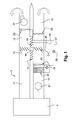
- the figure 1 shows an exemplary embodiment of an air treatment unit 1 according to the invention, for treating the air of a computer room 2.
- the air treatment unit 1 of the figure 1 comprises a return duct 17 of the hot air of the room, for example in communication with a false ceiling of the room 2 comprising areas allowing air to pass; and a cold air injection duct 16, for example in communication with a false floor of the room 2 comprising areas allowing air to pass.
- the air treatment unit 1 also comprises an external air intake duct 15 and an exhaust duct 18.
- the unit 1 comprises a mixing box, or register box 10, provided with four registers 11, 12, 13 and 14.
- the first register 11 is suitable to put in communication the free air sampling duct 15 with the cold air injection duct 16.
- the second damper 12 is able to put the air intake duct 17 in communication with the injection duct. 16.
- the third damper 13 is able to put the return air duct 17 into communication with the air evacuation duct 18.
- the fourth damper 14 is able to put the evacuation duct in communication with one another.
- the first three registers 11, 12, and 13 are modulating registers, that is to say with variable opening, while the fourth register 14 is an "all or nothing" type opening register.
- the means for controlling the humidity of the injected air comprise a humidifier 20 for humidifying if necessary the air to be injected without bringing him energy, so without heating it.
- the humidifier 20 is an adiabatic humidifier which has the advantage of consuming little energy. It can be of type spray, spray, ultrasound, runoff ... If it is necessary, dehumidification of the air will be achieved by condensation of moisture during the passage of air injected through the battery 19, which does not require any particular device.
- the condensing coil 23 and the evaporation battery 19 are connected by a first conduit 25 comprising an expansion valve 26 and a second conduit 27 comprising a refrigerating compressor 28. These elements constitute the cooling circuit of the treatment unit. air 1.
- the duct 10 for free air intake integrates, upstream of the mixing box 10, a filter box 22, comprising one or more stages of dust filter according to the required level of filtration.
- the principle of use of this unit is to pulsate the outside air directly into the room when its temperature allows it, that is to say when it is low enough to ensure the cooling of the room.
- This ideal situation can not of course persist, there are several modes of operation "seasonal".
- T ext the outside air temperature
- T p the air pulse set point temperature in the computer room
- T rep the room return air temperature of the computer room.
- the air pulse instruction temperature T p and T rep are parameters set by the user of the computer room.
- the first of these three modes is described below in relation to the figure 2 , called the "winter" mode, and which is applicable when T ext ⁇ T p .
- the first three registers 11, 12 and 13 have a variable opening from 0 to 100%, while the fourth register 14 is closed.
- the first and third registers 11 and 13 will always have the same value of opening while the second register 12 will have a complementary value of opening, that is to say equal to 100% minus the value of d opening the first 11 or third 13 register.
- the register 12 When T ext is less than T p , the register 12 will open gradually and the registers 11 and 13 will gradually close to mix the outside air with the air taken from the room (which is at a higher temperature than outside air), in a variable proportion.
- the proportion of the mixture will be regulated so as to guarantee a pulse temperature substantially equal to T p .
- the outside air is filtered through the filter box 22 to ensure the necessary air quality, and it is then mixed with air in the register box 10, passes through the humidifier 20 in which it is humidified if necessary, then is pulsed in the computer room 2 using the fan 21.
- the exhaust fan 24 takes up the air fraction of the room that is not re-circulated and rejects it. 'outside.
- the refrigerating circuit 19, 23, 25-28, the evaporation battery 19 and the condensation battery 23 are at a standstill (as well as the compressor 28) and therefore consume no energy.
- Humidifier 20 allows the forced air in room 2 to meet the minimum moisture requirements of ASHRAE discussed above. For a computer room located at a latitude corresponding to Western Europe, this mode of operation, which is the most energy efficient, is used almost 80% of the year.
- the second of the three modes applicable when T p ⁇ T ext ⁇ T rep , called the mode "between season".
- the first and third registers 11 and 13 are open at 100%
- the second and fourth registers 12 and 14 are closed.
- the outside air passes through the sampling duct 15 and the filter box 22, the evaporation battery 19 where it is cooled so as to pulsate the air in the room 2 at a temperature T p .
- the air is pulsed in the computer room 2 by the pulse fan 21.
- the power of the refrigerating circuit 19, 23, 25-28 is regulated so as to provide the cooling capacity necessary for the evaporation battery 19.
- the air The warm room 2 is taken by the exhaust fan 24, through the condensing coil 23 it cools and is rejected outside.
- the registers 11 and 13 are closed, while the second register 12 is open at 100%.
- the air taken up in the room is thus completely recycled, flowing through the air intake duct 17 and the injection circuit 16.
- the return air is cooled through the evaporation battery 19.
- the outside air circulates from the sampling duct 15 to the exhaust duct 18, thus serving to evacuate the heat available in the condensing coil 23. This operation is used at mid-latitudes in Western Europe, only a few hours per year. It corresponds to the classic operating mode of the computer room air conditioning cabinets previously described.
- the fans 21 and extraction 24 are equipped with frequency inverters in order to be able to modulate their flow rates, which makes it possible to adapt the air flow supplied to that required by the computer room and to guarantee, at any time, the overpressure in the computer room.
- the flow rate of the fan 21 will advantageously be regulated according to the heat load in the computer room.
- the flow rate of the exhaust fan 24 will be advantageously regulated so as to permanently ensure a relative overpressure of the cold areas the computer room compared to hot areas, for example of the order of 5 to 10 Pascal. This is one of the many advantages of the invention compared to conventional systems: guarantee through the overpressure in cold areas, that cold air is available everywhere in the computer room.
- the air treatment unit according to the invention makes it possible to use outside air directly to cool the computer room, throughout the year, and whatever the external humidity, and in very wide temperature ranges.
- a conventional value of the air intake setpoint temperature will be 30 °.
- the outside air will be used as soon as its temperature is below the air intake set point temperature, in this example 30 ° C.
- the air handling unit used in its most economical mode (the winter mode), as soon as the outside air temperature will be lower than the air supply setpoint temperature, a conventional value of which is for example 18 ° C. If we compare these values with the average annual temperature of the city of Paris, close to 12 ° C, we see that in a large number of geographical areas, the outside air will be exploitable within the framework of the invention almost all year, with the resulting energy savings.
- the arrangement of air intakes and air rejects parallel to the ventilation group that is to say on one or two opposite faces as illustrated in FIG. Figures 2 to 4 , and not on the side faces, allows the juxtaposition of units next to each other, which ensures a certain level of redundancy.
- the flow of air is represented by the arrow 31.
- the design of the present variant starts from the observation that the evaporation and condensation batteries can be unused nearly 80% of the time. However, these are responsible for a significant airflow loss, which must be compensated by the fan (pulse or extraction as appropriate), which induces power consumption by the fan. However, in a processing unit according to the invention, the consumption of the two fans (drive and extraction) represents more than 75% of the total power consumption of the system. There is therefore a great energetic interest in reducing air-pressure losses wherever possible.
- the solution proposed by this variant is to bypass the battery 32 when it is unused (80% of the time), by opening the registers 33 and 34 which thus allow the air flow to avoid the battery.
- the equivalent pressure drop in this configuration is almost zero.
- the registers 33 and 34 are closed and force the air to pass through the battery 32.
- This embodiment has the advantage that the outside air can be usable for a greater part of the year than with the systems known in the prior art.
Landscapes
- Engineering & Computer Science (AREA)
- Signal Processing (AREA)
- Chemical & Material Sciences (AREA)
- Combustion & Propulsion (AREA)
- Mechanical Engineering (AREA)
- General Engineering & Computer Science (AREA)
- Physics & Mathematics (AREA)
- Fuzzy Systems (AREA)
- Mathematical Physics (AREA)
- Air Conditioning Control Device (AREA)
Applications Claiming Priority (1)
| Application Number | Priority Date | Filing Date | Title |
|---|---|---|---|
| BE2009/0801A BE1019118A5 (fr) | 2009-12-21 | 2009-12-21 | Unite, procede et systeme de traitement d'air. |
Publications (2)
| Publication Number | Publication Date |
|---|---|
| EP2336661A1 true EP2336661A1 (de) | 2011-06-22 |
| EP2336661B1 EP2336661B1 (de) | 2017-09-13 |
Family
ID=42289330
Family Applications (1)
| Application Number | Title | Priority Date | Filing Date |
|---|---|---|---|
| EP10195536.7A Not-in-force EP2336661B1 (de) | 2009-12-21 | 2010-12-17 | Luftaufbereitungseinheit, -verfahren und -system |
Country Status (2)
| Country | Link |
|---|---|
| EP (1) | EP2336661B1 (de) |
| BE (1) | BE1019118A5 (de) |
Cited By (7)
| Publication number | Priority date | Publication date | Assignee | Title |
|---|---|---|---|---|
| USD754664S1 (en) | 2013-03-15 | 2016-04-26 | Ch2M Hill Engineers, Inc. | Modular pod |
| EP3026357A3 (de) * | 2014-11-27 | 2016-06-08 | Energy Cool ApS | Belüftungssystem |
| EP3054224A1 (de) * | 2015-02-09 | 2016-08-10 | LG Electronics Inc. | Klimaanlage |
| CN106766005A (zh) * | 2017-02-14 | 2017-05-31 | 国网新疆电力公司信息通信公司 | 用于机房的控制系统及方法 |
| US9713289B2 (en) | 2013-01-28 | 2017-07-18 | Ch2M Hill Engineers, Inc. | Modular pod |
| JP2017156023A (ja) * | 2016-03-02 | 2017-09-07 | 株式会社デンソー | 空調装置 |
| WO2019036954A1 (zh) * | 2017-08-23 | 2019-02-28 | 深圳企管加企业服务有限公司 | 基于物联网的机房温度、湿度控制方法、装置及存储介质 |
Citations (10)
| Publication number | Priority date | Publication date | Assignee | Title |
|---|---|---|---|---|
| DE3027447A1 (de) * | 1980-07-19 | 1982-02-11 | Horst Joachim 6700 Ludwigshafen Schmittel | Vorrichtung zur be- und entlueftung |
| EP0055000A1 (de) * | 1980-12-19 | 1982-06-30 | Philips Patentverwaltung GmbH | Vorrichtung zum Belüften und Heizen von Innenräumen |
| EP0294730A2 (de) | 1987-06-08 | 1988-12-14 | HANSA VENTILATOREN UND MASCHINENBAU NEUMANN GMBH & CO. KG | Raumlufttechnisches Gerät |
| WO1997006390A1 (en) * | 1995-08-08 | 1997-02-20 | Turcotte Inc. | Combined air exchange and air-conditioning unit |
| EP0909926A1 (de) * | 1997-10-14 | 1999-04-21 | Aldes Aeraulique | Belüftungssystem mit Doppelströmung |
| DE20101676U1 (de) * | 2001-01-19 | 2001-03-29 | Hansa Ventilatoren Und Maschinenbau Neumann Gmbh & Co Kg, 26683 Saterland | Klimagerät zur Luftbehandlung eines Raumes |
| WO2003073012A1 (de) | 2002-02-27 | 2003-09-04 | Hansa Ventilatoren Und Maschinenbau Neumann Gmbh & Co. Kg | Klimagerät |
| US6684653B2 (en) | 2001-11-21 | 2004-02-03 | Nicholas H. Des Champs | Air-conditioner and air-to-air heat exchange for closed loop cooling |
| EP2082635A2 (de) | 2006-09-06 | 2009-07-29 | KyotoCooling International B.V. | Vorrichtung und verfahren zum kühlen eines raums in einer datenzentrale mittels rezirkulationsluft |
| US20090210096A1 (en) | 2008-02-19 | 2009-08-20 | Liebert Corporation | Climate control system for data centers |
-
2009
- 2009-12-21 BE BE2009/0801A patent/BE1019118A5/fr not_active IP Right Cessation
-
2010
- 2010-12-17 EP EP10195536.7A patent/EP2336661B1/de not_active Not-in-force
Patent Citations (10)
| Publication number | Priority date | Publication date | Assignee | Title |
|---|---|---|---|---|
| DE3027447A1 (de) * | 1980-07-19 | 1982-02-11 | Horst Joachim 6700 Ludwigshafen Schmittel | Vorrichtung zur be- und entlueftung |
| EP0055000A1 (de) * | 1980-12-19 | 1982-06-30 | Philips Patentverwaltung GmbH | Vorrichtung zum Belüften und Heizen von Innenräumen |
| EP0294730A2 (de) | 1987-06-08 | 1988-12-14 | HANSA VENTILATOREN UND MASCHINENBAU NEUMANN GMBH & CO. KG | Raumlufttechnisches Gerät |
| WO1997006390A1 (en) * | 1995-08-08 | 1997-02-20 | Turcotte Inc. | Combined air exchange and air-conditioning unit |
| EP0909926A1 (de) * | 1997-10-14 | 1999-04-21 | Aldes Aeraulique | Belüftungssystem mit Doppelströmung |
| DE20101676U1 (de) * | 2001-01-19 | 2001-03-29 | Hansa Ventilatoren Und Maschinenbau Neumann Gmbh & Co Kg, 26683 Saterland | Klimagerät zur Luftbehandlung eines Raumes |
| US6684653B2 (en) | 2001-11-21 | 2004-02-03 | Nicholas H. Des Champs | Air-conditioner and air-to-air heat exchange for closed loop cooling |
| WO2003073012A1 (de) | 2002-02-27 | 2003-09-04 | Hansa Ventilatoren Und Maschinenbau Neumann Gmbh & Co. Kg | Klimagerät |
| EP2082635A2 (de) | 2006-09-06 | 2009-07-29 | KyotoCooling International B.V. | Vorrichtung und verfahren zum kühlen eines raums in einer datenzentrale mittels rezirkulationsluft |
| US20090210096A1 (en) | 2008-02-19 | 2009-08-20 | Liebert Corporation | Climate control system for data centers |
Cited By (7)
| Publication number | Priority date | Publication date | Assignee | Title |
|---|---|---|---|---|
| US9713289B2 (en) | 2013-01-28 | 2017-07-18 | Ch2M Hill Engineers, Inc. | Modular pod |
| USD754664S1 (en) | 2013-03-15 | 2016-04-26 | Ch2M Hill Engineers, Inc. | Modular pod |
| EP3026357A3 (de) * | 2014-11-27 | 2016-06-08 | Energy Cool ApS | Belüftungssystem |
| EP3054224A1 (de) * | 2015-02-09 | 2016-08-10 | LG Electronics Inc. | Klimaanlage |
| JP2017156023A (ja) * | 2016-03-02 | 2017-09-07 | 株式会社デンソー | 空調装置 |
| CN106766005A (zh) * | 2017-02-14 | 2017-05-31 | 国网新疆电力公司信息通信公司 | 用于机房的控制系统及方法 |
| WO2019036954A1 (zh) * | 2017-08-23 | 2019-02-28 | 深圳企管加企业服务有限公司 | 基于物联网的机房温度、湿度控制方法、装置及存储介质 |
Also Published As
| Publication number | Publication date |
|---|---|
| BE1019118A5 (fr) | 2012-03-06 |
| EP2336661B1 (de) | 2017-09-13 |
Similar Documents
| Publication | Publication Date | Title |
|---|---|---|
| EP2336661B1 (de) | Luftaufbereitungseinheit, -verfahren und -system | |
| EP2339908B1 (de) | Verfahren und Vorrichtung zur Reduzierung des Energieverbrauchs eines Zentrums, das mit energiefressenden Geräten ausgestattet ist | |
| EP1329344B1 (de) | Anordnung zur thermischen Verwaltung, insbesondere für ein Fahrzeug, das mit einer Brennstoffzelle ausgerüstet ist | |
| EP1857363A1 (de) | Temperaturregelvorrichtung | |
| EP3931089B1 (de) | Klimaanlage für eine flugzeugkabine mit vorrichtung zur wiedererwärmung des von dem wasserextraktionskreis gesammelten wassers | |
| FR3006430A1 (fr) | Systeme de refroidissement, systeme informatique refroidi et installation informatique | |
| WO2021053227A1 (fr) | Unité de conditionnement d'air pour aéronef | |
| EP2629023B1 (de) | Thermische Anlage und thermische Konditionierung eines Raums sowie Erzeugung von sanitärem Warmwasser | |
| EP2951420A1 (de) | Anlage mit einer gasturbine und verfahren zur regelung dieser anlage | |
| US11092075B2 (en) | High-capacity electric energy storage system for gas turbine based power plants | |
| EP2498588B1 (de) | Verfahren zur thermischen Steuerung einer elektrischen Energieumwandlungsanlage, und Anlage zur Umsetzung dieses Verfahrens | |
| EP2339909B1 (de) | Verfahren und Vorrichtung zur Reduzierung des Energieverbrauchs eines Zentrums, das mit energiefressenden Geräten ausgestattet ist | |
| FR2996980A1 (fr) | Dispositif et procede pour refroidissement de salle informatique | |
| FR3033632B1 (fr) | Dispositif thermodynamique de transfert de chaleur par compression de vapeur (mono ou multi-etage) et changements de phase, reversible a haut rendement. | |
| FR3074889A1 (fr) | Systeme et procede de refroidissement d'un flux gazeux au moyen d'un evaporateur | |
| CA3150655A1 (fr) | Systeme d'appoint pour un reseau de distribution d'energie thermique basse temperature | |
| EP3751207B1 (de) | Luftaufbereitungssystem mit doppelströmung und angemessener trocknung für gebäude mit wasseraktivitäten | |
| FR2974619A1 (fr) | Installation thermique | |
| FR2825143A1 (fr) | Systeme monobloc et installation de production alternative ou simultanee d'eau chaude ou d'eau glacee par transfert thermique | |
| FR3096117A1 (fr) | Dispositif de ventilation d’un local | |
| WO2026022015A1 (fr) | Système de traitement d'air à haute efficacité énergétique pour la gestion de la température et de l'humidité dans une enceinte | |
| FR3163609A1 (fr) | Dispositif de management thermique d’un véhicule comportant une chaine de traction électrique | |
| FR2913757A1 (fr) | Dispositif de couplage d'un systeme de chauffage a liquide caloporteur a un dispositif de refroidissement | |
| FR3032026A1 (fr) | Installation de ventilation mecanique controlee a recuperation thermodynamique et/ou statique a haut rendement pour la ventilation et le chauffage/rafraichissement | |
| FR3137534A1 (fr) | Système de déshumidification de l’air au sein d’une structure de culture close et structure de culture close équipée d’un tel système de déshumidification. |
Legal Events
| Date | Code | Title | Description |
|---|---|---|---|
| PUAI | Public reference made under article 153(3) epc to a published international application that has entered the european phase |
Free format text: ORIGINAL CODE: 0009012 |
|
| AK | Designated contracting states |
Kind code of ref document: A1 Designated state(s): AL AT BE BG CH CY CZ DE DK EE ES FI FR GB GR HR HU IE IS IT LI LT LU LV MC MK MT NL NO PL PT RO RS SE SI SK SM TR |
|
| AX | Request for extension of the european patent |
Extension state: BA ME |
|
| 17P | Request for examination filed |
Effective date: 20111201 |
|
| 17Q | First examination report despatched |
Effective date: 20130327 |
|
| GRAP | Despatch of communication of intention to grant a patent |
Free format text: ORIGINAL CODE: EPIDOSNIGR1 |
|
| INTG | Intention to grant announced |
Effective date: 20170411 |
|
| GRAS | Grant fee paid |
Free format text: ORIGINAL CODE: EPIDOSNIGR3 |
|
| GRAA | (expected) grant |
Free format text: ORIGINAL CODE: 0009210 |
|
| AK | Designated contracting states |
Kind code of ref document: B1 Designated state(s): AL AT BE BG CH CY CZ DE DK EE ES FI FR GB GR HR HU IE IS IT LI LT LU LV MC MK MT NL NO PL PT RO RS SE SI SK SM TR |
|
| REG | Reference to a national code |
Ref country code: GB Ref legal event code: FG4D Free format text: NOT ENGLISH |
|
| REG | Reference to a national code |
Ref country code: CH Ref legal event code: EP |
|
| REG | Reference to a national code |
Ref country code: IE Ref legal event code: FG4D Free format text: LANGUAGE OF EP DOCUMENT: FRENCH |
|
| REG | Reference to a national code |
Ref country code: AT Ref legal event code: REF Ref document number: 928556 Country of ref document: AT Kind code of ref document: T Effective date: 20171015 |
|
| REG | Reference to a national code |
Ref country code: DE Ref legal event code: R096 Ref document number: 602010045175 Country of ref document: DE |
|
| REG | Reference to a national code |
Ref country code: NL Ref legal event code: MP Effective date: 20170913 |
|
| REG | Reference to a national code |
Ref country code: LT Ref legal event code: MG4D |
|
| PG25 | Lapsed in a contracting state [announced via postgrant information from national office to epo] |
Ref country code: FI Free format text: LAPSE BECAUSE OF FAILURE TO SUBMIT A TRANSLATION OF THE DESCRIPTION OR TO PAY THE FEE WITHIN THE PRESCRIBED TIME-LIMIT Effective date: 20170913 Ref country code: HR Free format text: LAPSE BECAUSE OF FAILURE TO SUBMIT A TRANSLATION OF THE DESCRIPTION OR TO PAY THE FEE WITHIN THE PRESCRIBED TIME-LIMIT Effective date: 20170913 Ref country code: NO Free format text: LAPSE BECAUSE OF FAILURE TO SUBMIT A TRANSLATION OF THE DESCRIPTION OR TO PAY THE FEE WITHIN THE PRESCRIBED TIME-LIMIT Effective date: 20171213 Ref country code: SE Free format text: LAPSE BECAUSE OF FAILURE TO SUBMIT A TRANSLATION OF THE DESCRIPTION OR TO PAY THE FEE WITHIN THE PRESCRIBED TIME-LIMIT Effective date: 20170913 Ref country code: LT Free format text: LAPSE BECAUSE OF FAILURE TO SUBMIT A TRANSLATION OF THE DESCRIPTION OR TO PAY THE FEE WITHIN THE PRESCRIBED TIME-LIMIT Effective date: 20170913 |
|
| REG | Reference to a national code |
Ref country code: AT Ref legal event code: MK05 Ref document number: 928556 Country of ref document: AT Kind code of ref document: T Effective date: 20170913 |
|
| PG25 | Lapsed in a contracting state [announced via postgrant information from national office to epo] |
Ref country code: GR Free format text: LAPSE BECAUSE OF FAILURE TO SUBMIT A TRANSLATION OF THE DESCRIPTION OR TO PAY THE FEE WITHIN THE PRESCRIBED TIME-LIMIT Effective date: 20171214 Ref country code: ES Free format text: LAPSE BECAUSE OF FAILURE TO SUBMIT A TRANSLATION OF THE DESCRIPTION OR TO PAY THE FEE WITHIN THE PRESCRIBED TIME-LIMIT Effective date: 20170913 Ref country code: BG Free format text: LAPSE BECAUSE OF FAILURE TO SUBMIT A TRANSLATION OF THE DESCRIPTION OR TO PAY THE FEE WITHIN THE PRESCRIBED TIME-LIMIT Effective date: 20171213 Ref country code: LV Free format text: LAPSE BECAUSE OF FAILURE TO SUBMIT A TRANSLATION OF THE DESCRIPTION OR TO PAY THE FEE WITHIN THE PRESCRIBED TIME-LIMIT Effective date: 20170913 Ref country code: RS Free format text: LAPSE BECAUSE OF FAILURE TO SUBMIT A TRANSLATION OF THE DESCRIPTION OR TO PAY THE FEE WITHIN THE PRESCRIBED TIME-LIMIT Effective date: 20170913 |
|
| PG25 | Lapsed in a contracting state [announced via postgrant information from national office to epo] |
Ref country code: NL Free format text: LAPSE BECAUSE OF FAILURE TO SUBMIT A TRANSLATION OF THE DESCRIPTION OR TO PAY THE FEE WITHIN THE PRESCRIBED TIME-LIMIT Effective date: 20170913 |
|
| PG25 | Lapsed in a contracting state [announced via postgrant information from national office to epo] |
Ref country code: PL Free format text: LAPSE BECAUSE OF FAILURE TO SUBMIT A TRANSLATION OF THE DESCRIPTION OR TO PAY THE FEE WITHIN THE PRESCRIBED TIME-LIMIT Effective date: 20170913 Ref country code: RO Free format text: LAPSE BECAUSE OF FAILURE TO SUBMIT A TRANSLATION OF THE DESCRIPTION OR TO PAY THE FEE WITHIN THE PRESCRIBED TIME-LIMIT Effective date: 20170913 Ref country code: CZ Free format text: LAPSE BECAUSE OF FAILURE TO SUBMIT A TRANSLATION OF THE DESCRIPTION OR TO PAY THE FEE WITHIN THE PRESCRIBED TIME-LIMIT Effective date: 20170913 |
|
| PG25 | Lapsed in a contracting state [announced via postgrant information from national office to epo] |
Ref country code: IS Free format text: LAPSE BECAUSE OF FAILURE TO SUBMIT A TRANSLATION OF THE DESCRIPTION OR TO PAY THE FEE WITHIN THE PRESCRIBED TIME-LIMIT Effective date: 20180113 Ref country code: IT Free format text: LAPSE BECAUSE OF FAILURE TO SUBMIT A TRANSLATION OF THE DESCRIPTION OR TO PAY THE FEE WITHIN THE PRESCRIBED TIME-LIMIT Effective date: 20170913 Ref country code: SK Free format text: LAPSE BECAUSE OF FAILURE TO SUBMIT A TRANSLATION OF THE DESCRIPTION OR TO PAY THE FEE WITHIN THE PRESCRIBED TIME-LIMIT Effective date: 20170913 Ref country code: AT Free format text: LAPSE BECAUSE OF FAILURE TO SUBMIT A TRANSLATION OF THE DESCRIPTION OR TO PAY THE FEE WITHIN THE PRESCRIBED TIME-LIMIT Effective date: 20170913 Ref country code: SM Free format text: LAPSE BECAUSE OF FAILURE TO SUBMIT A TRANSLATION OF THE DESCRIPTION OR TO PAY THE FEE WITHIN THE PRESCRIBED TIME-LIMIT Effective date: 20170913 Ref country code: EE Free format text: LAPSE BECAUSE OF FAILURE TO SUBMIT A TRANSLATION OF THE DESCRIPTION OR TO PAY THE FEE WITHIN THE PRESCRIBED TIME-LIMIT Effective date: 20170913 |
|
| REG | Reference to a national code |
Ref country code: DE Ref legal event code: R097 Ref document number: 602010045175 Country of ref document: DE |
|
| REG | Reference to a national code |
Ref country code: DE Ref legal event code: R119 Ref document number: 602010045175 Country of ref document: DE |
|
| PLBE | No opposition filed within time limit |
Free format text: ORIGINAL CODE: 0009261 |
|
| STAA | Information on the status of an ep patent application or granted ep patent |
Free format text: STATUS: NO OPPOSITION FILED WITHIN TIME LIMIT |
|
| PG25 | Lapsed in a contracting state [announced via postgrant information from national office to epo] |
Ref country code: DK Free format text: LAPSE BECAUSE OF FAILURE TO SUBMIT A TRANSLATION OF THE DESCRIPTION OR TO PAY THE FEE WITHIN THE PRESCRIBED TIME-LIMIT Effective date: 20170913 |
|
| REG | Reference to a national code |
Ref country code: CH Ref legal event code: PL |
|
| 26N | No opposition filed |
Effective date: 20180614 |
|
| GBPC | Gb: european patent ceased through non-payment of renewal fee |
Effective date: 20171217 |
|
| REG | Reference to a national code |
Ref country code: IE Ref legal event code: MM4A |
|
| PG25 | Lapsed in a contracting state [announced via postgrant information from national office to epo] |
Ref country code: LU Free format text: LAPSE BECAUSE OF NON-PAYMENT OF DUE FEES Effective date: 20171217 Ref country code: MT Free format text: LAPSE BECAUSE OF FAILURE TO SUBMIT A TRANSLATION OF THE DESCRIPTION OR TO PAY THE FEE WITHIN THE PRESCRIBED TIME-LIMIT Effective date: 20170913 |
|
| REG | Reference to a national code |
Ref country code: FR Ref legal event code: ST Effective date: 20180831 |
|
| PG25 | Lapsed in a contracting state [announced via postgrant information from national office to epo] |
Ref country code: IE Free format text: LAPSE BECAUSE OF NON-PAYMENT OF DUE FEES Effective date: 20171217 Ref country code: FR Free format text: LAPSE BECAUSE OF NON-PAYMENT OF DUE FEES Effective date: 20180102 Ref country code: DE Free format text: LAPSE BECAUSE OF NON-PAYMENT OF DUE FEES Effective date: 20180703 |
|
| PG25 | Lapsed in a contracting state [announced via postgrant information from national office to epo] |
Ref country code: GB Free format text: LAPSE BECAUSE OF NON-PAYMENT OF DUE FEES Effective date: 20171217 Ref country code: LI Free format text: LAPSE BECAUSE OF NON-PAYMENT OF DUE FEES Effective date: 20171231 Ref country code: SI Free format text: LAPSE BECAUSE OF FAILURE TO SUBMIT A TRANSLATION OF THE DESCRIPTION OR TO PAY THE FEE WITHIN THE PRESCRIBED TIME-LIMIT Effective date: 20170913 Ref country code: CH Free format text: LAPSE BECAUSE OF NON-PAYMENT OF DUE FEES Effective date: 20171231 |
|
| PG25 | Lapsed in a contracting state [announced via postgrant information from national office to epo] |
Ref country code: HU Free format text: LAPSE BECAUSE OF FAILURE TO SUBMIT A TRANSLATION OF THE DESCRIPTION OR TO PAY THE FEE WITHIN THE PRESCRIBED TIME-LIMIT; INVALID AB INITIO Effective date: 20101217 Ref country code: MC Free format text: LAPSE BECAUSE OF FAILURE TO SUBMIT A TRANSLATION OF THE DESCRIPTION OR TO PAY THE FEE WITHIN THE PRESCRIBED TIME-LIMIT Effective date: 20170913 |
|
| PG25 | Lapsed in a contracting state [announced via postgrant information from national office to epo] |
Ref country code: CY Free format text: LAPSE BECAUSE OF NON-PAYMENT OF DUE FEES Effective date: 20170913 |
|
| PG25 | Lapsed in a contracting state [announced via postgrant information from national office to epo] |
Ref country code: MK Free format text: LAPSE BECAUSE OF FAILURE TO SUBMIT A TRANSLATION OF THE DESCRIPTION OR TO PAY THE FEE WITHIN THE PRESCRIBED TIME-LIMIT Effective date: 20170913 |
|
| PG25 | Lapsed in a contracting state [announced via postgrant information from national office to epo] |
Ref country code: TR Free format text: LAPSE BECAUSE OF FAILURE TO SUBMIT A TRANSLATION OF THE DESCRIPTION OR TO PAY THE FEE WITHIN THE PRESCRIBED TIME-LIMIT Effective date: 20170913 |
|
| PG25 | Lapsed in a contracting state [announced via postgrant information from national office to epo] |
Ref country code: PT Free format text: LAPSE BECAUSE OF FAILURE TO SUBMIT A TRANSLATION OF THE DESCRIPTION OR TO PAY THE FEE WITHIN THE PRESCRIBED TIME-LIMIT Effective date: 20170913 |
|
| PG25 | Lapsed in a contracting state [announced via postgrant information from national office to epo] |
Ref country code: AL Free format text: LAPSE BECAUSE OF FAILURE TO SUBMIT A TRANSLATION OF THE DESCRIPTION OR TO PAY THE FEE WITHIN THE PRESCRIBED TIME-LIMIT Effective date: 20170913 |
|
| PGFP | Annual fee paid to national office [announced via postgrant information from national office to epo] |
Ref country code: BE Payment date: 20221122 Year of fee payment: 13 |
|
| REG | Reference to a national code |
Ref country code: BE Ref legal event code: MM Effective date: 20231231 |
|
| PG25 | Lapsed in a contracting state [announced via postgrant information from national office to epo] |
Ref country code: BE Free format text: LAPSE BECAUSE OF NON-PAYMENT OF DUE FEES Effective date: 20231231 |
|
| PG25 | Lapsed in a contracting state [announced via postgrant information from national office to epo] |
Ref country code: BE Free format text: LAPSE BECAUSE OF NON-PAYMENT OF DUE FEES Effective date: 20231231 |