EP2336697A2 - Echangeur thermique avec des éléments extrudés et empilés - Google Patents
Echangeur thermique avec des éléments extrudés et empilés Download PDFInfo
- Publication number
- EP2336697A2 EP2336697A2 EP10193673A EP10193673A EP2336697A2 EP 2336697 A2 EP2336697 A2 EP 2336697A2 EP 10193673 A EP10193673 A EP 10193673A EP 10193673 A EP10193673 A EP 10193673A EP 2336697 A2 EP2336697 A2 EP 2336697A2
- Authority
- EP
- European Patent Office
- Prior art keywords
- heat exchanger
- conduit means
- shoe
- plug
- conduit
- Prior art date
- Legal status (The legal status is an assumption and is not a legal conclusion. Google has not performed a legal analysis and makes no representation as to the accuracy of the status listed.)
- Granted
Links
- 238000009826 distribution Methods 0.000 claims description 7
- 238000007599 discharging Methods 0.000 claims description 3
- 230000002349 favourable effect Effects 0.000 description 21
- 238000005452 bending Methods 0.000 description 10
- 239000002826 coolant Substances 0.000 description 10
- 238000001816 cooling Methods 0.000 description 8
- 239000012530 fluid Substances 0.000 description 8
- 238000004519 manufacturing process Methods 0.000 description 7
- 244000089486 Phragmites australis subsp australis Species 0.000 description 3
- 238000003780 insertion Methods 0.000 description 3
- 230000037431 insertion Effects 0.000 description 3
- 229910052751 metal Inorganic materials 0.000 description 3
- 239000002184 metal Substances 0.000 description 3
- 125000006850 spacer group Chemical group 0.000 description 3
- 229910052782 aluminium Inorganic materials 0.000 description 2
- XAGFODPZIPBFFR-UHFFFAOYSA-N aluminium Chemical compound [Al] XAGFODPZIPBFFR-UHFFFAOYSA-N 0.000 description 2
- 238000000926 separation method Methods 0.000 description 2
- 238000004891 communication Methods 0.000 description 1
- 238000005520 cutting process Methods 0.000 description 1
- 238000005304 joining Methods 0.000 description 1
- 230000013011 mating Effects 0.000 description 1
- 229910000679 solder Inorganic materials 0.000 description 1
- 238000005476 soldering Methods 0.000 description 1
- 238000003466 welding Methods 0.000 description 1
Images


Classifications
-
- F—MECHANICAL ENGINEERING; LIGHTING; HEATING; WEAPONS; BLASTING
- F28—HEAT EXCHANGE IN GENERAL
- F28D—HEAT-EXCHANGE APPARATUS, NOT PROVIDED FOR IN ANOTHER SUBCLASS, IN WHICH THE HEAT-EXCHANGE MEDIA DO NOT COME INTO DIRECT CONTACT
- F28D1/00—Heat-exchange apparatus having stationary conduit assemblies for one heat-exchange medium only, the media being in contact with different sides of the conduit wall, in which the other heat-exchange medium is a large body of fluid, e.g. domestic or motor car radiators
- F28D1/02—Heat-exchange apparatus having stationary conduit assemblies for one heat-exchange medium only, the media being in contact with different sides of the conduit wall, in which the other heat-exchange medium is a large body of fluid, e.g. domestic or motor car radiators with heat-exchange conduits immersed in the body of fluid
- F28D1/04—Heat-exchange apparatus having stationary conduit assemblies for one heat-exchange medium only, the media being in contact with different sides of the conduit wall, in which the other heat-exchange medium is a large body of fluid, e.g. domestic or motor car radiators with heat-exchange conduits immersed in the body of fluid with tubular conduits
- F28D1/053—Heat-exchange apparatus having stationary conduit assemblies for one heat-exchange medium only, the media being in contact with different sides of the conduit wall, in which the other heat-exchange medium is a large body of fluid, e.g. domestic or motor car radiators with heat-exchange conduits immersed in the body of fluid with tubular conduits the conduits being straight
- F28D1/0535—Heat-exchange apparatus having stationary conduit assemblies for one heat-exchange medium only, the media being in contact with different sides of the conduit wall, in which the other heat-exchange medium is a large body of fluid, e.g. domestic or motor car radiators with heat-exchange conduits immersed in the body of fluid with tubular conduits the conduits being straight the conduits having a non-circular cross-section
- F28D1/05358—Assemblies of conduits connected side by side or with individual headers, e.g. section type radiators
-
- F—MECHANICAL ENGINEERING; LIGHTING; HEATING; WEAPONS; BLASTING
- F28—HEAT EXCHANGE IN GENERAL
- F28F—DETAILS OF HEAT-EXCHANGE AND HEAT-TRANSFER APPARATUS, OF GENERAL APPLICATION
- F28F1/00—Tubular elements; Assemblies of tubular elements
- F28F1/02—Tubular elements of cross-section which is non-circular
- F28F1/022—Tubular elements of cross-section which is non-circular with multiple channels
-
- F—MECHANICAL ENGINEERING; LIGHTING; HEATING; WEAPONS; BLASTING
- F28—HEAT EXCHANGE IN GENERAL
- F28F—DETAILS OF HEAT-EXCHANGE AND HEAT-TRANSFER APPARATUS, OF GENERAL APPLICATION
- F28F2255/00—Heat exchanger elements made of materials having special features or resulting from particular manufacturing processes
- F28F2255/16—Heat exchanger elements made of materials having special features or resulting from particular manufacturing processes extruded
Definitions
- the present invention relates to a heat exchanger according to claim 1.
- the DE 10 2006 054460 A1 shows a heat exchanger with a plurality of stacked and interconnected conduit means having at their ends in each case a through hole for supplying or discharging a medium.
- welded tubes are used with turbulence insert as conduit means, the use of such a tube is very expensive to manufacture, since several steps are to be carried out for the production of such a tube and such a tube can be soldered flux-free with difficulty.
- this in turn only allows the use of a chemically resistant oil as a coolant.
- Other conventional Samnlerkonstructions from the bottom and lid are also inflexible in the variation of the number of tubes.
- the present invention provides a heat exchanger, in particular for a motor vehicle, with a plurality of stacked and interconnected conduit means, in particular flat tubes, each having a through hole for feeding or discharging a medium at their ends, wherein the conduit ends are each received in a plug shoe and wherein the glovessseinnchtungen are each made of an integrally produced extruded profile element with fluid-tight inner channels.
- the present invention is based on the finding that a heat exchanger which is economical and easy to produce and at the same time effective can be produced if an extruded profile element with fluid-tight inner channels is used for the conduit device.
- a standard component can advantageously be used for the conduit devices of the heat exchanger. This, in turn, eliminates the laborious welding of a tube with a turbulence insert or the joining of a profile to a lid and a bottom.
- the combination of the slip-on principle with an extruded profile promises a flexible and cost-effective solution for direct heat exchangers such as oil / air coolers or coolant coolers.
- At least one inner duct arranged on an outer edge of a duct device may have a larger cross-sectional area than an inner duct arranged in a central region of the duct device.
- Such an embodiment of the present invention has the advantage that the side walls of the conduit device, in particular if this is designed as a flat tube, are used in addition to the cooling. In this case, a larger amount of coolant can be passed through these inner channels at the outer edge of the conduit means, so that a more effective cooling of the total amount of the coolant can be achieved.
- a distance between an inner tube wall and a land adjacent the inner tube wall may be greater than with an inner channel disposed in the central region of the conduit means.
- the inside of at least one inner channel may have a ribbed shape, such that at least one web extends in the inner channel from the wall of the inner channel towards the middle of the inner channel.
- a large heat transfer surface can be formed in this inner channel through the web which extends in the direction of the center of the inner channel, so that effective cooling by the heat exchanger becomes possible.
- At least one of the inner channels of the conduit means may also have at least partially an H-shape.
- Such a shape of an inner channel has a particularly good heat transfer property, since, for example, with respect to a cylindrical inner channel, a very large area of inner walls of such an inner channel for the transfer of heat is available.
- all inner channels may be opened towards the through hole.
- Such an embodiment of the present invention has the advantage that in this way a particularly uniform supply of the inner channels is ensured with the guided through the through hole in the conduit means fluid.
- the through-hole may have a circular shape and be concentric with a bore in the male shoe.
- Such an embodiment of the present invention offers the advantage that a particularly uniform and low-friction supply of the inner channels with the fluid or the coolant can be ensured.
- this low friction can be ensured because the fluid or the coolant does not have to flow around such a cutting edge.
- the through hole extends beyond an end edge of at least one conduit means, wherein a Budapestss adopted of a conduit means is received by the plug shoe, that with the help of the plug shoe, a fluid-permeable distribution channel of the through hole on the front side of the conduit means an inner channel is formed on an outer wall of the conduit means.
- a side surface of the plug shoe can be used effectively as a heat exchange surface. In this way, an enlargement of the available heat exchange surface can be made possible, which offers an even better cooling property of a heat exchanger designed in this way.
- a favorable embodiment of the heat exchanger is characterized in that a plurality of patch shoes are stacked one above the other.
- the patch shoes replace the manifolds used in conventional heat exchangers to receive the conduit ends.
- Another favorable embodiment of the heat exchanger is characterized in that the plug-in shoe is embossed from a stamped part. As a result, the production costs can be kept low.
- the plug-in shoe is integrally formed from two halves which are interconnected by a preferably extending in the transverse direction of the conduit means bending edge or bending line.
- the plug shoe is formed by a substantially rectangular plate which is divided by the bending edge or bending line into two substantially rectangular halves which are folded together.
- the plate is preferably formed of sheet metal, in particular aluminum sheet.
- Another favorable embodiment of the heat exchanger is characterized in that the two plug shoe halves have a recessed edge region, with which the plug shoe halves abut each other.
- the male shoe halves are soldered together at their edge regions.
- a further advantageous embodiment of the heat exchanger is characterized in that the recessed edge regions delimit a trough-shaped receiving space for a line device end.
- the trough-shaped receiving space is open at one end and surrounds the associated conduit end.
- the plug-in shoe has two through-holes, which are arranged concentrically to each other.
- the through holes allow the inclusion or leakage of the medium in the associated conduit means.
- a further advantageous embodiment of the heat exchanger is characterized in that the edge regions of the through holes are raised and each have substantially the shape of a cup having a bottom, in which the associated through hole is saved from.
- the boot takes on the function of a spacer between two conduit devices.
- Another favorable embodiment of the heat exchanger is characterized in that a plurality of conduit means, in particular flat tubes, are arranged side by side. As a result, the production of multi-row heat exchangers is made possible in a simple manner.
- Another favorable embodiment of the heat exchanger is characterized in that two conduit means, in particular flat tubes, are arranged side by side. As a result, the production of double-row heat exchangers is made possible in a simple manner.
- a further favorable exemplary embodiment of the heat exchanger is characterized in that the line device ends of at least two line devices arranged side by side, in particular flat tubes, are accommodated in each case in a multiple plug-in shoe. This simplifies pre-assembly.
- Another favorable embodiment of the heat exchanger is characterized in that a plurality of multiple plug-in shoes are stacked one above the other.
- the multiple sockets replace the headers used in conventional heat exchangers to receive the conduit ends.
- Another favorable embodiment of the heat exchanger is characterized in that the Mehrfachsteckschuh is embossed from a stamped part. As a result, the production costs can be kept low.
- Another favorable embodiment of the heat exchanger is characterized in that the Mehrfachsteckschuh is integrally formed of two halves, which are interconnected by a running in the transverse direction of the Kirss adopted bending edge or bending line. As a result, the assembly of the heat exchanger according to the invention is simplified.
- the heat exchanger is characterized in that the Mehrfachsteckschuh has a plurality of separate receiving areas for each one line device end. Depending on the application, the recording areas may also be in communication with each other.
- Another favorable embodiment of the heat exchanger is characterized in that the receiving areas are separated for each one line device end by a separation region in which the two halves, of which the Mehrfachsteckschuh is integrally formed, are tightly interconnected.
- the two halves are in the separation region preferably cohesively, for example, by soldering, tightly interconnected.
- the heat exchanger is characterized in that the Mehrfachsteckschuh is formed by a substantially rectangular plate, which is divided by the bending edge or bending line in two substantially rectangular halves, which are folded.
- the plate is preferably formed of sheet metal, in particular aluminum sheet.
- Another favorable embodiment of the heat exchanger is characterized in that the two Mehrfachsteckschuhhquen recessed edge portions which, at least partially, extend around the receiving areas around and with which the Mehrfachsteckschuhhquen abut each other.
- the Mehrfachsteckschuhhbankn are soldered together at their edge regions.
- Another favorable embodiment of the heat exchanger is characterized in that the recessed edge regions each delimit a trough-shaped receiving space for a line device end.
- the trough-shaped receiving spaces are open at one end and embrace the associated conduit end.
- Another favorable embodiment of the heat exchanger is characterized in that the Mehrfachsteckschuh in each receiving area has two through holes, which are arranged concentrically to each other. The through holes allow the inlet or outlet of the medium in the associated conduit means.
- Another favorable embodiment of the heat exchanger is characterized in that the edge regions of the through holes are raised and each have substantially the shape of a cup having a bottom, in which the associated through hole is recessed.
- the Mehrtachsteckschuh assumes the function of a spacer between two conduit means, both between two side by side and, together with another Mehrfachsteckschuh, between two superimposed conduit means.
- a cooler 1 (also referred to as a heat exchanger) is shown in perspective.
- the radiator 1 comprises seven flat tubes 3 to 9 which are arranged one above the other. The ends of the flat tubes 3 to 9 are each received in a Einsteckschuh 11 to 17, 21 to 27.
- Fig. 2a is the radiator 1 off Fig. 1 shown in longitudinal section.
- the Einsteck gum 11 to 17, 21 to 27 are arranged one above the other in two stacks.
- the flat tubes are arranged parallel to each other.
- the slip-on shoes serve as spacers.
- an air ordeffenleit worn 31 to 36 is arranged between two flat tubes 3 to 9 in each case.
- the flat tube 3 can also be replaced by a base plate, which closes the radiator 1 down.
- the flat tube 9 through a cover plate be replaced, which closes the radiator 1 upwards.
- the flat tubes 3 to 9 each have at their ends at least one opening through which a medium to be cooled, in particular a coolant, can enter or exit.
- the flat tubes 3 to 9 are flowed through in the longitudinal direction of the medium to be cooled.
- the flat tubes 3 to 9 with another coolant, for example, with air, applied, or the flat tubes 3 to 9 perpendicular to the plane in Fig. 2a flows around.
- the other coolant for example the air, flows in a drawing plane according to the Fig. 2b , where in Fig. 2b is a plan view of an embodiment of the invention.
- the prior art uses a welded tube with turbulence insert. This pipe is more expensive than an extruded profile and difficult to solder fluxless.
- an extruded profile 200 is used with fluid-tight inner channels 210, as for example, as a sectional view in Fig. 2c is gestgestelft.
- the tube ends 212 each have a bore (either circular as shown in FIG. 2d or out of round as shown Fig. 2f ) appropriate.
- the extruded profile is designed, for example, so that at the 2 outer chambers 214, the distance between the tube wall 216 and the first (outermost) vertical web 218 is greater than in the inner chambers 220 (ie, the chambers or channels 220, the further from Pipe end 212 or a pipe side wall are away as the outer chambers 214.
- Fig. 2e shows an isometric view of an entire extruded tube 200, as it can be used as a conduit means 3 to 9 in the heat exchanger 1 use.
- the bore 222 is designed so that the two outer channels 214 are open to bore 222 back. In this way it can be achieved that on the one hand good cooling of a large amount of fluid through the outer channels 214 is enabled. On the other hand, it can also be ensured at the same time that no excessive friction loss occurs in these outer channels 214 due to the further outer channels 214, which causes uneven flow behavior in all inner channels 210 and thus causes undesired pressure fluctuations in the heat exchanger 1.
- the bore 222 may be replaced by an opening 224 towards the tube end (but with minor strength disadvantages.)
- An embodiment of such an opening 224 in a tube 200 is shown in FIG Fig. 2f shown in isometric view. Again, then not necessarily the outer channels 214 must be opened when between the pipe end and bending edge 48 of the boot 11-17 and 21-27 a distribution channel, as will be described in more detail below.
- extruded profiles 200 compared to simple turbulence liners according to the prior art thus allows a cost reduction compared to today's manufacturing process with welded tubes or extruded profiles with separately welded or soldered bottom and lid.
- the above-mentioned insertion shoes can also advantageously be used again here.
- the plug shoe principle the number of tubes can be easily changed.
- the insertion shoe 41 is formed by a substantially rectangular plate 42 made of sheet metal.
- the plate 42 is divided by a bend line 48 into two halves 44 and 45, which are also referred to as flanks.
- the two halves 44, 45 each have substantially the shape of a rectangle.
- the halves 44, 45 have a recessed edge region 51, 52 on three of its sides.
- the halves 44, 45 each have a raised, cup-shaped region 55, 56.
- the cup-shaped region 55, 56 is each provided with a central through hole 61, 62.
- the upper side of the cup-shaped region 55, 56 is arranged at a distance 64 to the upper side of the plate 42.
- the two halves 44, 45 of the Einsteckschuhs 41 are pivotable about the bending line 48.
- the two halves 44, 45 are arranged at an angle of 90 degrees to each other.
- the two halves 44, 45 are opposite to in the Fig. 3 to Fig.5 illustrated unfolded position in which the two halves 44, 45 are arranged in a plane, each pivoted by 45 degrees.
- the recessed edge regions 51, 52 of the two halves 44, 45 abut each other.
- the raised areas 55, 56 are then turned away from each other.
- the through holes 61, 62, 222 are then arranged in alignment.
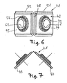
- Fig. 8 representations of a folded in end position check shoe from different Russianionsnchtungen reproduced.
- a slip-in shoe 41 is shown in the folded state in plan view.
- the Einsteckschuh 41 shown from the front view
- the left representation of the insertion shoe 41 is shown in accordance with the middle view from a left direction of view.
- the lower illustration off Fig. 8 is the Einsteckschuh 41 from a rear view.
- the lines of intersection are shown along the line CC, as in the middle illustration Fig. 8 is defined.
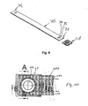
- a flat tube 70 is shown in perspective, having two ends 71, 72.
- the end 71 of the flat tube 70 has two through holes 74, 75, which are arranged concentrically in the top and the bottom of the flat tube 70.
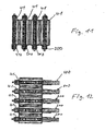
- Fig. 10 shows a plan view of a pipe-plug connection, wherein the tube has a circular opening. It is from the FIG. 10 it can be seen that the central through-hole in the plug-in shoe 61, 62 is concentric with the bore 222 in the extruded profile 200, wherein in this embodiment the bore 222 has a circular shape. Consequently, therefore, the cup and the cup opening of the plug shoe 41 is arranged concentrically to this bore 222. Furthermore, in the Fig. 10 a section line AA and a second section line BB entered, which are used to explain the following representations. Fig. 11 shows a sectional view corresponding to a section line AA according to Fig. 10 , where in Fig.
- a heat exchanger 1 is shown with a plurality of conduit means and these conduit means are formed as an extruded profile 200, as described above.
- Fig. 12 shows a sectional view along the longitudinal section line BB Fig. 10 , where in Fig. 10 a heat exchanger 1 with a plurality of conduit means 200 is shown.
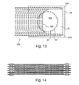
- Fig. 13 shows a plan view of a non-round punched-out tube in a plug-in shoe 41, wherein a distribution channel 230 between an end face of the tube 200, the plug shoe 41 and the two outer inner channels 214.
- the extruded profile 200 which is used as a conduit means, cut out of round, that is, it is open continuously to a front or end side 212, in particular in the form of an arc 224. If the two outer channels 214 are not fluid-permeable directly to the bore 224, one or more distribution channels 230 should be formed over the end face and the plug-in shoe 41 be to introduce the fluid from the bore 224 in the outer channels or 214.
- FIGS. 14 to 17 Figure 4 shows photographic representations of views of some embodiments of the present invention. It is in the picture off Fig. 14 a side view of a heat exchanger described above imaged. In the Fig. 15 a combination of a plug-in shoe with an extruded profile tube is shown before the plug-in shoe has been mounted on the tube. In the picture off Fig. 16 is an isometric view of a combination of a plug shoe and an extruded profile played before mating, now the inner channels are clearly visible in the extruded profile tube. In the Fig. 17 is to be used for an embodiment of the present invention extruded profile with inner channels and a bore through which also the lateral, outer and other inner channels are opened to the bore.
Landscapes
- Engineering & Computer Science (AREA)
- Physics & Mathematics (AREA)
- Thermal Sciences (AREA)
- Mechanical Engineering (AREA)
- General Engineering & Computer Science (AREA)
- Geometry (AREA)
- Heat-Exchange Devices With Radiators And Conduit Assemblies (AREA)
Applications Claiming Priority (1)
| Application Number | Priority Date | Filing Date | Title |
|---|---|---|---|
| DE102009058069A DE102009058069A1 (de) | 2009-12-14 | 2009-12-14 | Wärmetauscher |
Publications (3)
| Publication Number | Publication Date |
|---|---|
| EP2336697A2 true EP2336697A2 (fr) | 2011-06-22 |
| EP2336697A3 EP2336697A3 (fr) | 2015-02-18 |
| EP2336697B1 EP2336697B1 (fr) | 2016-08-10 |
Family
ID=43733939
Family Applications (1)
| Application Number | Title | Priority Date | Filing Date |
|---|---|---|---|
| EP10193673.0A Not-in-force EP2336697B1 (fr) | 2009-12-14 | 2010-12-03 | Echangeur thermique avec des éléments extrudés et empilés |
Country Status (2)
| Country | Link |
|---|---|
| EP (1) | EP2336697B1 (fr) |
| DE (1) | DE102009058069A1 (fr) |
Cited By (1)
| Publication number | Priority date | Publication date | Assignee | Title |
|---|---|---|---|---|
| JP2022117538A (ja) * | 2021-02-01 | 2022-08-12 | パナソニックIpマネジメント株式会社 | プレートフィン積層型熱交換器およびそれを用いた冷凍システム |
Families Citing this family (3)
| Publication number | Priority date | Publication date | Assignee | Title |
|---|---|---|---|---|
| US9151540B2 (en) | 2010-06-29 | 2015-10-06 | Johnson Controls Technology Company | Multichannel heat exchanger tubes with flow path inlet sections |
| DE102015204984A1 (de) * | 2015-03-19 | 2016-10-06 | Mahle International Gmbh | Wärmetauscher, insbesondere für eine Abwärmenutzungseinrichtung |
| DE102024116356A1 (de) * | 2024-06-11 | 2025-12-11 | Akg Verwaltungsgesellschaft Mbh | Wärmeaustauscher |
Citations (1)
| Publication number | Priority date | Publication date | Assignee | Title |
|---|---|---|---|---|
| DE102006054460A1 (de) | 2005-11-17 | 2007-05-24 | Behr Gmbh & Co. Kg | Wärmetauscher |
Family Cites Families (8)
| Publication number | Priority date | Publication date | Assignee | Title |
|---|---|---|---|---|
| DE3615300A1 (de) * | 1986-05-06 | 1987-11-12 | Norsk Hydro As | Kuehlrohre, sowie verfahren und vorrichtung zu deren herstellung |
| JP3113100B2 (ja) * | 1992-11-05 | 2000-11-27 | 株式会社デンソー | 多穴管押出用ダイス及び多穴管 |
| DE19719260C1 (de) * | 1997-05-07 | 1998-09-24 | Valeo Klimatech Gmbh & Co Kg | Gepreßtes Flachrohr für Wärmetauscher in Kraftfahrzeugen |
| JPH11230693A (ja) * | 1998-02-17 | 1999-08-27 | Showa Alum Corp | 熱交換器 |
| FR2858399B1 (fr) * | 2003-07-29 | 2005-10-28 | Valeo Thermique Moteur Sa | Embout de tube pour element de circuit hydraulique, en particulier pour echangeur de chaleur |
| FR2860288B1 (fr) * | 2003-09-26 | 2005-11-11 | Valeo Thermique Moteur Sa | Element de circuit pour echangeur de chaleur, et echangeur de chaleur ainsi obtenu |
| FR2864215B1 (fr) * | 2003-12-19 | 2011-07-15 | Valeo Climatisation | Element de circuit pour echangeur de chaleur |
| EP1788334A3 (fr) * | 2005-11-17 | 2009-04-08 | Behr GmbH & Co. KG | Echangeur de chaleur |
-
2009
- 2009-12-14 DE DE102009058069A patent/DE102009058069A1/de not_active Withdrawn
-
2010
- 2010-12-03 EP EP10193673.0A patent/EP2336697B1/fr not_active Not-in-force
Patent Citations (1)
| Publication number | Priority date | Publication date | Assignee | Title |
|---|---|---|---|---|
| DE102006054460A1 (de) | 2005-11-17 | 2007-05-24 | Behr Gmbh & Co. Kg | Wärmetauscher |
Cited By (1)
| Publication number | Priority date | Publication date | Assignee | Title |
|---|---|---|---|---|
| JP2022117538A (ja) * | 2021-02-01 | 2022-08-12 | パナソニックIpマネジメント株式会社 | プレートフィン積層型熱交換器およびそれを用いた冷凍システム |
Also Published As
| Publication number | Publication date |
|---|---|
| DE102009058069A1 (de) | 2011-06-16 |
| EP2336697A3 (fr) | 2015-02-18 |
| EP2336697B1 (fr) | 2016-08-10 |
Similar Documents
| Publication | Publication Date | Title |
|---|---|---|
| DE112014004486B4 (de) | Wärmetauscher mit integriertem koaxialen Einlass-/Auslassrohr | |
| DE60117693T2 (de) | Wärmetauscher, insbesondere als Kraftstoffkühler bei Brennkraftmaschinen von Kraftfahrzeugen | |
| DE69428219T2 (de) | Plattenwärmetauscher | |
| DE10392610B4 (de) | Verbesserter Wärmeübertrager | |
| DE69316121T2 (de) | Plattenwärmetauscher | |
| DE69626295T2 (de) | Plattenwärmetauscher | |
| DE60009282T2 (de) | Wärmetauscher mit genopptem bypasskanal | |
| WO1996038699A1 (fr) | Echangeur de chaleur | |
| EP1348924A2 (fr) | Echangeur de chaleur à gaz d'échappement pour véhicule | |
| WO2003054467A1 (fr) | Echangeur thermique notamment destine a un vehicule | |
| DE602006000470T2 (de) | Luftgekühlter Ölkühler | |
| DE112009000888T5 (de) | Kalibrierte Umgehungsstruktur für einen Wärmetauscher | |
| DE20307881U1 (de) | Wärmeaustauscher, insbesondere Ladeluftkühler | |
| DE3500571A1 (de) | Kuehler fuer kraftfahrzeuge | |
| WO2014131756A1 (fr) | Échangeur de chaleur | |
| DE69007709T2 (de) | Stapelverdampfer. | |
| DE102008033594A1 (de) | Boden für einen Wärmetauscher | |
| EP1929233B1 (fr) | Refroidisseur d'air de suralimentation ou refroidisseur de gaz d'echappement pour un moteur a combustion interne d'un vehicule automobile | |
| EP2336697B1 (fr) | Echangeur thermique avec des éléments extrudés et empilés | |
| EP2438384B1 (fr) | Tuyau collecteur pour condenseur | |
| DE69613918T2 (de) | Wärmetauscher mit Adapter | |
| EP1798506B1 (fr) | Evaporateur | |
| DE102005059920B4 (de) | Wärmetauscher, insbesondere Verdampfer | |
| DE102006043526A1 (de) | Wärmetauscher, inbesondere Ladeluftkühler oder Abgaskühler für eine Brennkraftmaschine eines Kraftfahrzeuges | |
| EP0819906B1 (fr) | Raccord adaptateur pour échangeur de chaleur à plaques |
Legal Events
| Date | Code | Title | Description |
|---|---|---|---|
| PUAI | Public reference made under article 153(3) epc to a published international application that has entered the european phase |
Free format text: ORIGINAL CODE: 0009012 |
|
| AK | Designated contracting states |
Kind code of ref document: A2 Designated state(s): AL AT BE BG CH CY CZ DE DK EE ES FI FR GB GR HR HU IE IS IT LI LT LU LV MC MK MT NL NO PL PT RO RS SE SI SK SM TR |
|
| AX | Request for extension of the european patent |
Extension state: BA ME |
|
| PUAL | Search report despatched |
Free format text: ORIGINAL CODE: 0009013 |
|
| AK | Designated contracting states |
Kind code of ref document: A3 Designated state(s): AL AT BE BG CH CY CZ DE DK EE ES FI FR GB GR HR HU IE IS IT LI LT LU LV MC MK MT NL NO PL PT RO RS SE SI SK SM TR |
|
| AX | Request for extension of the european patent |
Extension state: BA ME |
|
| RIC1 | Information provided on ipc code assigned before grant |
Ipc: F28F 1/02 20060101ALI20150114BHEP Ipc: F28D 1/053 20060101AFI20150114BHEP |
|
| RAP1 | Party data changed (applicant data changed or rights of an application transferred) |
Owner name: MAHLE BEHR GMBH & CO. KG |
|
| 17P | Request for examination filed |
Effective date: 20150818 |
|
| RBV | Designated contracting states (corrected) |
Designated state(s): AL AT BE BG CH CY CZ DE DK EE ES FI FR GB GR HR HU IE IS IT LI LT LU LV MC MK MT NL NO PL PT RO RS SE SI SK SM TR |
|
| GRAP | Despatch of communication of intention to grant a patent |
Free format text: ORIGINAL CODE: EPIDOSNIGR1 |
|
| INTG | Intention to grant announced |
Effective date: 20160122 |
|
| GRAP | Despatch of communication of intention to grant a patent |
Free format text: ORIGINAL CODE: EPIDOSNIGR1 |
|
| RIN1 | Information on inventor provided before grant (corrected) |
Inventor name: RICHTER, JENS |
|
| GRAS | Grant fee paid |
Free format text: ORIGINAL CODE: EPIDOSNIGR3 |
|
| GRAA | (expected) grant |
Free format text: ORIGINAL CODE: 0009210 |
|
| INTG | Intention to grant announced |
Effective date: 20160620 |
|
| AK | Designated contracting states |
Kind code of ref document: B1 Designated state(s): AL AT BE BG CH CY CZ DE DK EE ES FI FR GB GR HR HU IE IS IT LI LT LU LV MC MK MT NL NO PL PT RO RS SE SI SK SM TR |
|
| REG | Reference to a national code |
Ref country code: GB Ref legal event code: FG4D Free format text: NOT ENGLISH |
|
| REG | Reference to a national code |
Ref country code: CH Ref legal event code: EP Ref country code: AT Ref legal event code: REF Ref document number: 819447 Country of ref document: AT Kind code of ref document: T Effective date: 20160815 |
|
| REG | Reference to a national code |
Ref country code: IE Ref legal event code: FG4D Free format text: LANGUAGE OF EP DOCUMENT: GERMAN |
|
| REG | Reference to a national code |
Ref country code: DE Ref legal event code: R096 Ref document number: 502010012152 Country of ref document: DE |
|
| REG | Reference to a national code |
Ref country code: LT Ref legal event code: MG4D |
|
| REG | Reference to a national code |
Ref country code: NL Ref legal event code: MP Effective date: 20160810 |
|
| REG | Reference to a national code |
Ref country code: FR Ref legal event code: PLFP Year of fee payment: 7 |
|
| PG25 | Lapsed in a contracting state [announced via postgrant information from national office to epo] |
Ref country code: IT Free format text: LAPSE BECAUSE OF FAILURE TO SUBMIT A TRANSLATION OF THE DESCRIPTION OR TO PAY THE FEE WITHIN THE PRESCRIBED TIME-LIMIT Effective date: 20160810 Ref country code: HR Free format text: LAPSE BECAUSE OF FAILURE TO SUBMIT A TRANSLATION OF THE DESCRIPTION OR TO PAY THE FEE WITHIN THE PRESCRIBED TIME-LIMIT Effective date: 20160810 Ref country code: LT Free format text: LAPSE BECAUSE OF FAILURE TO SUBMIT A TRANSLATION OF THE DESCRIPTION OR TO PAY THE FEE WITHIN THE PRESCRIBED TIME-LIMIT Effective date: 20160810 Ref country code: NL Free format text: LAPSE BECAUSE OF FAILURE TO SUBMIT A TRANSLATION OF THE DESCRIPTION OR TO PAY THE FEE WITHIN THE PRESCRIBED TIME-LIMIT Effective date: 20160810 Ref country code: IS Free format text: LAPSE BECAUSE OF FAILURE TO SUBMIT A TRANSLATION OF THE DESCRIPTION OR TO PAY THE FEE WITHIN THE PRESCRIBED TIME-LIMIT Effective date: 20161210 Ref country code: NO Free format text: LAPSE BECAUSE OF FAILURE TO SUBMIT A TRANSLATION OF THE DESCRIPTION OR TO PAY THE FEE WITHIN THE PRESCRIBED TIME-LIMIT Effective date: 20161110 Ref country code: RS Free format text: LAPSE BECAUSE OF FAILURE TO SUBMIT A TRANSLATION OF THE DESCRIPTION OR TO PAY THE FEE WITHIN THE PRESCRIBED TIME-LIMIT Effective date: 20160810 Ref country code: FI Free format text: LAPSE BECAUSE OF FAILURE TO SUBMIT A TRANSLATION OF THE DESCRIPTION OR TO PAY THE FEE WITHIN THE PRESCRIBED TIME-LIMIT Effective date: 20160810 |
|
| PG25 | Lapsed in a contracting state [announced via postgrant information from national office to epo] |
Ref country code: SE Free format text: LAPSE BECAUSE OF FAILURE TO SUBMIT A TRANSLATION OF THE DESCRIPTION OR TO PAY THE FEE WITHIN THE PRESCRIBED TIME-LIMIT Effective date: 20160810 Ref country code: PT Free format text: LAPSE BECAUSE OF FAILURE TO SUBMIT A TRANSLATION OF THE DESCRIPTION OR TO PAY THE FEE WITHIN THE PRESCRIBED TIME-LIMIT Effective date: 20161212 Ref country code: ES Free format text: LAPSE BECAUSE OF FAILURE TO SUBMIT A TRANSLATION OF THE DESCRIPTION OR TO PAY THE FEE WITHIN THE PRESCRIBED TIME-LIMIT Effective date: 20160810 Ref country code: GR Free format text: LAPSE BECAUSE OF FAILURE TO SUBMIT A TRANSLATION OF THE DESCRIPTION OR TO PAY THE FEE WITHIN THE PRESCRIBED TIME-LIMIT Effective date: 20161111 Ref country code: LV Free format text: LAPSE BECAUSE OF FAILURE TO SUBMIT A TRANSLATION OF THE DESCRIPTION OR TO PAY THE FEE WITHIN THE PRESCRIBED TIME-LIMIT Effective date: 20160810 Ref country code: PL Free format text: LAPSE BECAUSE OF FAILURE TO SUBMIT A TRANSLATION OF THE DESCRIPTION OR TO PAY THE FEE WITHIN THE PRESCRIBED TIME-LIMIT Effective date: 20160810 |
|
| PG25 | Lapsed in a contracting state [announced via postgrant information from national office to epo] |
Ref country code: RO Free format text: LAPSE BECAUSE OF FAILURE TO SUBMIT A TRANSLATION OF THE DESCRIPTION OR TO PAY THE FEE WITHIN THE PRESCRIBED TIME-LIMIT Effective date: 20160810 Ref country code: EE Free format text: LAPSE BECAUSE OF FAILURE TO SUBMIT A TRANSLATION OF THE DESCRIPTION OR TO PAY THE FEE WITHIN THE PRESCRIBED TIME-LIMIT Effective date: 20160810 |
|
| REG | Reference to a national code |
Ref country code: DE Ref legal event code: R097 Ref document number: 502010012152 Country of ref document: DE |
|
| PG25 | Lapsed in a contracting state [announced via postgrant information from national office to epo] |
Ref country code: BE Free format text: LAPSE BECAUSE OF NON-PAYMENT OF DUE FEES Effective date: 20161231 Ref country code: SK Free format text: LAPSE BECAUSE OF FAILURE TO SUBMIT A TRANSLATION OF THE DESCRIPTION OR TO PAY THE FEE WITHIN THE PRESCRIBED TIME-LIMIT Effective date: 20160810 Ref country code: DK Free format text: LAPSE BECAUSE OF FAILURE TO SUBMIT A TRANSLATION OF THE DESCRIPTION OR TO PAY THE FEE WITHIN THE PRESCRIBED TIME-LIMIT Effective date: 20160810 Ref country code: SM Free format text: LAPSE BECAUSE OF FAILURE TO SUBMIT A TRANSLATION OF THE DESCRIPTION OR TO PAY THE FEE WITHIN THE PRESCRIBED TIME-LIMIT Effective date: 20160810 Ref country code: CZ Free format text: LAPSE BECAUSE OF FAILURE TO SUBMIT A TRANSLATION OF THE DESCRIPTION OR TO PAY THE FEE WITHIN THE PRESCRIBED TIME-LIMIT Effective date: 20160810 Ref country code: BG Free format text: LAPSE BECAUSE OF FAILURE TO SUBMIT A TRANSLATION OF THE DESCRIPTION OR TO PAY THE FEE WITHIN THE PRESCRIBED TIME-LIMIT Effective date: 20161110 |
|
| PLBE | No opposition filed within time limit |
Free format text: ORIGINAL CODE: 0009261 |
|
| STAA | Information on the status of an ep patent application or granted ep patent |
Free format text: STATUS: NO OPPOSITION FILED WITHIN TIME LIMIT |
|
| 26N | No opposition filed |
Effective date: 20170511 |
|
| REG | Reference to a national code |
Ref country code: CH Ref legal event code: PL |
|
| GBPC | Gb: european patent ceased through non-payment of renewal fee |
Effective date: 20161203 |
|
| PG25 | Lapsed in a contracting state [announced via postgrant information from national office to epo] |
Ref country code: SI Free format text: LAPSE BECAUSE OF FAILURE TO SUBMIT A TRANSLATION OF THE DESCRIPTION OR TO PAY THE FEE WITHIN THE PRESCRIBED TIME-LIMIT Effective date: 20160810 |
|
| PG25 | Lapsed in a contracting state [announced via postgrant information from national office to epo] |
Ref country code: MC Free format text: LAPSE BECAUSE OF FAILURE TO SUBMIT A TRANSLATION OF THE DESCRIPTION OR TO PAY THE FEE WITHIN THE PRESCRIBED TIME-LIMIT Effective date: 20160810 |
|
| REG | Reference to a national code |
Ref country code: IE Ref legal event code: MM4A |
|
| PG25 | Lapsed in a contracting state [announced via postgrant information from national office to epo] |
Ref country code: CH Free format text: LAPSE BECAUSE OF NON-PAYMENT OF DUE FEES Effective date: 20161231 Ref country code: LU Free format text: LAPSE BECAUSE OF NON-PAYMENT OF DUE FEES Effective date: 20161203 Ref country code: LI Free format text: LAPSE BECAUSE OF NON-PAYMENT OF DUE FEES Effective date: 20161231 |
|
| PG25 | Lapsed in a contracting state [announced via postgrant information from national office to epo] |
Ref country code: GB Free format text: LAPSE BECAUSE OF NON-PAYMENT OF DUE FEES Effective date: 20161203 Ref country code: IE Free format text: LAPSE BECAUSE OF NON-PAYMENT OF DUE FEES Effective date: 20161203 |
|
| REG | Reference to a national code |
Ref country code: FR Ref legal event code: PLFP Year of fee payment: 8 |
|
| REG | Reference to a national code |
Ref country code: BE Ref legal event code: MM Effective date: 20161231 |
|
| REG | Reference to a national code |
Ref country code: AT Ref legal event code: MM01 Ref document number: 819447 Country of ref document: AT Kind code of ref document: T Effective date: 20161203 |
|
| PG25 | Lapsed in a contracting state [announced via postgrant information from national office to epo] |
Ref country code: HU Free format text: LAPSE BECAUSE OF FAILURE TO SUBMIT A TRANSLATION OF THE DESCRIPTION OR TO PAY THE FEE WITHIN THE PRESCRIBED TIME-LIMIT; INVALID AB INITIO Effective date: 20101203 Ref country code: AT Free format text: LAPSE BECAUSE OF NON-PAYMENT OF DUE FEES Effective date: 20161203 Ref country code: CY Free format text: LAPSE BECAUSE OF FAILURE TO SUBMIT A TRANSLATION OF THE DESCRIPTION OR TO PAY THE FEE WITHIN THE PRESCRIBED TIME-LIMIT Effective date: 20160810 |
|
| PG25 | Lapsed in a contracting state [announced via postgrant information from national office to epo] |
Ref country code: MK Free format text: LAPSE BECAUSE OF FAILURE TO SUBMIT A TRANSLATION OF THE DESCRIPTION OR TO PAY THE FEE WITHIN THE PRESCRIBED TIME-LIMIT Effective date: 20160810 Ref country code: TR Free format text: LAPSE BECAUSE OF FAILURE TO SUBMIT A TRANSLATION OF THE DESCRIPTION OR TO PAY THE FEE WITHIN THE PRESCRIBED TIME-LIMIT Effective date: 20160810 |
|
| PG25 | Lapsed in a contracting state [announced via postgrant information from national office to epo] |
Ref country code: MT Free format text: LAPSE BECAUSE OF FAILURE TO SUBMIT A TRANSLATION OF THE DESCRIPTION OR TO PAY THE FEE WITHIN THE PRESCRIBED TIME-LIMIT Effective date: 20160810 |
|
| PG25 | Lapsed in a contracting state [announced via postgrant information from national office to epo] |
Ref country code: AL Free format text: LAPSE BECAUSE OF FAILURE TO SUBMIT A TRANSLATION OF THE DESCRIPTION OR TO PAY THE FEE WITHIN THE PRESCRIBED TIME-LIMIT Effective date: 20160810 |
|
| PGFP | Annual fee paid to national office [announced via postgrant information from national office to epo] |
Ref country code: FR Payment date: 20191220 Year of fee payment: 10 |
|
| PGFP | Annual fee paid to national office [announced via postgrant information from national office to epo] |
Ref country code: DE Payment date: 20210216 Year of fee payment: 11 |
|
| PG25 | Lapsed in a contracting state [announced via postgrant information from national office to epo] |
Ref country code: FR Free format text: LAPSE BECAUSE OF NON-PAYMENT OF DUE FEES Effective date: 20201231 |
|
| REG | Reference to a national code |
Ref country code: DE Ref legal event code: R119 Ref document number: 502010012152 Country of ref document: DE |
|
| PG25 | Lapsed in a contracting state [announced via postgrant information from national office to epo] |
Ref country code: DE Free format text: LAPSE BECAUSE OF NON-PAYMENT OF DUE FEES Effective date: 20220701 |