EP2336710A2 - Dispositif de transition de déflagration à détonation - Google Patents
Dispositif de transition de déflagration à détonation Download PDFInfo
- Publication number
- EP2336710A2 EP2336710A2 EP10196047A EP10196047A EP2336710A2 EP 2336710 A2 EP2336710 A2 EP 2336710A2 EP 10196047 A EP10196047 A EP 10196047A EP 10196047 A EP10196047 A EP 10196047A EP 2336710 A2 EP2336710 A2 EP 2336710A2
- Authority
- EP
- European Patent Office
- Prior art keywords
- thermally stable
- explosive
- detonator
- stable secondary
- explosives
- Prior art date
- Legal status (The legal status is an assumption and is not a legal conclusion. Google has not performed a legal analysis and makes no representation as to the accuracy of the status listed.)
- Withdrawn
Links
- 238000005474 detonation Methods 0.000 title claims abstract description 76
- 238000004200 deflagration Methods 0.000 title claims abstract description 55
- 230000007704 transition Effects 0.000 title claims abstract description 52
- 239000002360 explosive Substances 0.000 claims abstract description 362
- 238000010304 firing Methods 0.000 claims abstract description 9
- 239000000203 mixture Substances 0.000 claims description 89
- 239000000463 material Substances 0.000 claims description 42
- DYGJZCCUSXSGBE-UHFFFAOYSA-N 1,3,5-trinitro-2,4-bis(2,4,6-trinitrophenyl)benzene Chemical compound [O-][N+](=O)C1=CC([N+](=O)[O-])=CC([N+]([O-])=O)=C1C1=C([N+]([O-])=O)C=C([N+]([O-])=O)C(C=2C(=CC(=CC=2[N+]([O-])=O)[N+]([O-])=O)[N+]([O-])=O)=C1[N+]([O-])=O DYGJZCCUSXSGBE-UHFFFAOYSA-N 0.000 claims description 40
- 239000003999 initiator Substances 0.000 claims description 38
- 230000008878 coupling Effects 0.000 claims description 16
- 238000010168 coupling process Methods 0.000 claims description 16
- 238000005859 coupling reaction Methods 0.000 claims description 16
- TZRXHJWUDPFEEY-UHFFFAOYSA-N Pentaerythritol Tetranitrate Chemical compound [O-][N+](=O)OCC(CO[N+]([O-])=O)(CO[N+]([O-])=O)CO[N+]([O-])=O TZRXHJWUDPFEEY-UHFFFAOYSA-N 0.000 claims description 15
- 230000004913 activation Effects 0.000 claims description 10
- IFPMZBBHBZQTOV-UHFFFAOYSA-N 1,3,5-trinitro-2-(2,4,6-trinitrophenyl)-4-[2,4,6-trinitro-3-(2,4,6-trinitrophenyl)phenyl]benzene Chemical compound [O-][N+](=O)C1=CC([N+](=O)[O-])=CC([N+]([O-])=O)=C1C1=C([N+]([O-])=O)C=C([N+]([O-])=O)C(C=2C(=C(C=3C(=CC(=CC=3[N+]([O-])=O)[N+]([O-])=O)[N+]([O-])=O)C(=CC=2[N+]([O-])=O)[N+]([O-])=O)[N+]([O-])=O)=C1[N+]([O-])=O IFPMZBBHBZQTOV-UHFFFAOYSA-N 0.000 claims description 6
- 239000000853 adhesive Substances 0.000 claims description 4
- 230000001070 adhesive effect Effects 0.000 claims description 4
- 238000009527 percussion Methods 0.000 claims description 4
- 239000004065 semiconductor Substances 0.000 claims description 3
- YSIBQULRFXITSW-OWOJBTEDSA-N 1,3,5-trinitro-2-[(e)-2-(2,4,6-trinitrophenyl)ethenyl]benzene Chemical compound [O-][N+](=O)C1=CC([N+](=O)[O-])=CC([N+]([O-])=O)=C1\C=C\C1=C([N+]([O-])=O)C=C([N+]([O-])=O)C=C1[N+]([O-])=O YSIBQULRFXITSW-OWOJBTEDSA-N 0.000 description 12
- 230000035945 sensitivity Effects 0.000 description 12
- 238000000034 method Methods 0.000 description 11
- 238000006243 chemical reaction Methods 0.000 description 7
- 239000000843 powder Substances 0.000 description 5
- 230000004044 response Effects 0.000 description 5
- 238000012360 testing method Methods 0.000 description 5
- 230000033228 biological regulation Effects 0.000 description 4
- 239000012530 fluid Substances 0.000 description 4
- 238000004519 manufacturing process Methods 0.000 description 4
- 229910052751 metal Inorganic materials 0.000 description 4
- 239000002184 metal Substances 0.000 description 4
- 229920003023 plastic Polymers 0.000 description 4
- 239000004033 plastic Substances 0.000 description 4
- WFKWXMTUELFFGS-UHFFFAOYSA-N tungsten Chemical compound [W] WFKWXMTUELFFGS-UHFFFAOYSA-N 0.000 description 4
- NDYLCHGXSQOGMS-UHFFFAOYSA-N CL-20 Chemical compound [O-][N+](=O)N1C2N([N+]([O-])=O)C3N([N+](=O)[O-])C2N([N+]([O-])=O)C2N([N+]([O-])=O)C3N([N+]([O-])=O)C21 NDYLCHGXSQOGMS-UHFFFAOYSA-N 0.000 description 3
- VYPSYNLAJGMNEJ-UHFFFAOYSA-N Silicium dioxide Chemical compound O=[Si]=O VYPSYNLAJGMNEJ-UHFFFAOYSA-N 0.000 description 3
- 238000013461 design Methods 0.000 description 3
- 230000008569 process Effects 0.000 description 3
- 239000000126 substance Substances 0.000 description 3
- 239000000026 Pentaerythritol tetranitrate Substances 0.000 description 2
- 239000000919 ceramic Substances 0.000 description 2
- 230000000694 effects Effects 0.000 description 2
- 230000008030 elimination Effects 0.000 description 2
- 238000003379 elimination reaction Methods 0.000 description 2
- 230000002708 enhancing effect Effects 0.000 description 2
- 229930195733 hydrocarbon Natural products 0.000 description 2
- 150000002430 hydrocarbons Chemical class 0.000 description 2
- 238000010348 incorporation Methods 0.000 description 2
- 230000001965 increasing effect Effects 0.000 description 2
- 230000000977 initiatory effect Effects 0.000 description 2
- 239000007769 metal material Substances 0.000 description 2
- 210000002445 nipple Anatomy 0.000 description 2
- 239000002245 particle Substances 0.000 description 2
- 239000008188 pellet Substances 0.000 description 2
- 229960004321 pentaerithrityl tetranitrate Drugs 0.000 description 2
- 229920000642 polymer Polymers 0.000 description 2
- 238000007493 shaping process Methods 0.000 description 2
- GOLXNESZZPUPJE-UHFFFAOYSA-N spiromesifen Chemical compound CC1=CC(C)=CC(C)=C1C(C(O1)=O)=C(OC(=O)CC(C)(C)C)C11CCCC1 GOLXNESZZPUPJE-UHFFFAOYSA-N 0.000 description 2
- -1 threads Substances 0.000 description 2
- 239000001993 wax Substances 0.000 description 2
- 238000003466 welding Methods 0.000 description 2
- LBJNLKPQJWBCID-UHFFFAOYSA-N 1,3,5-trinitro-2,4,6-tris(2,4,6-trinitrophenyl)benzene Chemical compound [O-][N+](=O)C1=CC([N+](=O)[O-])=CC([N+]([O-])=O)=C1C1=C([N+]([O-])=O)C(C=2C(=CC(=CC=2[N+]([O-])=O)[N+]([O-])=O)[N+]([O-])=O)=C([N+]([O-])=O)C(C=2C(=CC(=CC=2[N+]([O-])=O)[N+]([O-])=O)[N+]([O-])=O)=C1[N+]([O-])=O LBJNLKPQJWBCID-UHFFFAOYSA-N 0.000 description 1
- 239000004215 Carbon black (E152) Substances 0.000 description 1
- 101000794213 Homo sapiens Thymus-specific serine protease Proteins 0.000 description 1
- 239000005909 Kieselgur Substances 0.000 description 1
- 229910000831 Steel Inorganic materials 0.000 description 1
- 102100030138 Thymus-specific serine protease Human genes 0.000 description 1
- RTAQQCXQSZGOHL-UHFFFAOYSA-N Titanium Chemical compound [Ti] RTAQQCXQSZGOHL-UHFFFAOYSA-N 0.000 description 1
- BRVKWQLGXOHURH-UHFFFAOYSA-L [K+].C[N+](C)(C)C.[O-][Cl](=O)(=O)=O.[O-][Cl](=O)(=O)=O Chemical compound [K+].C[N+](C)(C)C.[O-][Cl](=O)(=O)=O.[O-][Cl](=O)(=O)=O BRVKWQLGXOHURH-UHFFFAOYSA-L 0.000 description 1
- 230000003213 activating effect Effects 0.000 description 1
- 230000004075 alteration Effects 0.000 description 1
- 150000001540 azides Chemical class 0.000 description 1
- 239000012964 benzotriazole Substances 0.000 description 1
- 239000011230 binding agent Substances 0.000 description 1
- 230000015572 biosynthetic process Effects 0.000 description 1
- 239000003990 capacitor Substances 0.000 description 1
- 230000008859 change Effects 0.000 description 1
- 238000002485 combustion reaction Methods 0.000 description 1
- 238000004891 communication Methods 0.000 description 1
- 239000002131 composite material Substances 0.000 description 1
- 150000001875 compounds Chemical class 0.000 description 1
- 238000011109 contamination Methods 0.000 description 1
- 238000002788 crimping Methods 0.000 description 1
- 239000013078 crystal Substances 0.000 description 1
- AXZAYXJCENRGIM-UHFFFAOYSA-J dipotassium;tetrabromoplatinum(2-) Chemical compound [K+].[K+].[Br-].[Br-].[Br-].[Br-].[Pt+2] AXZAYXJCENRGIM-UHFFFAOYSA-J 0.000 description 1
- 230000005611 electricity Effects 0.000 description 1
- 238000004880 explosion Methods 0.000 description 1
- 239000004744 fabric Substances 0.000 description 1
- 239000011152 fibreglass Substances 0.000 description 1
- 230000010006 flight Effects 0.000 description 1
- 239000000499 gel Substances 0.000 description 1
- 230000006872 improvement Effects 0.000 description 1
- 239000012535 impurity Substances 0.000 description 1
- 239000007788 liquid Substances 0.000 description 1
- 230000014759 maintenance of location Effects 0.000 description 1
- 230000007246 mechanism Effects 0.000 description 1
- 238000005065 mining Methods 0.000 description 1
- 229910052755 nonmetal Inorganic materials 0.000 description 1
- 229910001487 potassium perchlorate Inorganic materials 0.000 description 1
- 230000001902 propagating effect Effects 0.000 description 1
- 239000011208 reinforced composite material Substances 0.000 description 1
- 230000004043 responsiveness Effects 0.000 description 1
- 238000007789 sealing Methods 0.000 description 1
- 238000010008 shearing Methods 0.000 description 1
- 230000035939 shock Effects 0.000 description 1
- 238000004904 shortening Methods 0.000 description 1
- 239000000377 silicon dioxide Substances 0.000 description 1
- QBFXQJXHEPIJKW-UHFFFAOYSA-N silver azide Chemical compound [Ag+].[N-]=[N+]=[N-] QBFXQJXHEPIJKW-UHFFFAOYSA-N 0.000 description 1
- 230000000087 stabilizing effect Effects 0.000 description 1
- 230000003068 static effect Effects 0.000 description 1
- 239000010959 steel Substances 0.000 description 1
- 238000006467 substitution reaction Methods 0.000 description 1
- 230000008961 swelling Effects 0.000 description 1
- 239000010936 titanium Substances 0.000 description 1
- 229910052719 titanium Inorganic materials 0.000 description 1
- 238000002604 ultrasonography Methods 0.000 description 1
Images



Classifications
-
- F—MECHANICAL ENGINEERING; LIGHTING; HEATING; WEAPONS; BLASTING
- F42—AMMUNITION; BLASTING
- F42B—EXPLOSIVE CHARGES, e.g. FOR BLASTING, FIREWORKS, AMMUNITION
- F42B3/00—Blasting cartridges, i.e. case and explosive
- F42B3/10—Initiators therefor
-
- C—CHEMISTRY; METALLURGY
- C06—EXPLOSIVES; MATCHES
- C06C—DETONATING OR PRIMING DEVICES; FUSES; CHEMICAL LIGHTERS; PYROPHORIC COMPOSITIONS
- C06C7/00—Non-electric detonators; Blasting caps; Primers
-
- F—MECHANICAL ENGINEERING; LIGHTING; HEATING; WEAPONS; BLASTING
- F42—AMMUNITION; BLASTING
- F42C—AMMUNITION FUZES; ARMING OR SAFETY MEANS THEREFOR
- F42C19/00—Details of fuzes
- F42C19/08—Primers; Detonators
- F42C19/0803—Primers; Detonators characterised by the combination of per se known chemical composition in the priming substance
-
- F—MECHANICAL ENGINEERING; LIGHTING; HEATING; WEAPONS; BLASTING
- F42—AMMUNITION; BLASTING
- F42D—BLASTING
- F42D1/00—Blasting methods or apparatus, e.g. loading or tamping
- F42D1/04—Arrangements for ignition
Definitions
- High explosives and exploding devices are employed in a wide variety of commercial applications, for example, in mining, in hydrocarbon production, in building demolition, and in other applications.
- a high explosive may be categorized as either a primary explosive or a secondary explosive.
- Primary explosives are highly sensitive to stimuli such as impact, friction, heat, and/or electrostatic charges; secondary explosives are less sensitive to stimuli.
- PETN Pentaerythritol Tetranitrate
- Primary explosives may be identified as explosives that are more sensitive than PETN, and secondary explosives may be identified as explosives that are less sensitive than PETN.
- Explosives may be additionally characterized by a variety of different parameters including sensitivity to impact, thermal stability, ability to dent a standard metal plate when detonated, crystal size, shape, and other parameters.
- Explosives may take a variety of forms including liquids, gels, plastics, and powders. Explosive powders may be compressed to form dense pellets and/or shaped explosive charges. Explosives may comprise percentages of other non-explosive materials, for example, sawdust, powdered silica, diatomaceous earth, plastics, polymers, waxes, and other non-explosive materials. These additional non-explosive materials may contribute to stabilizing an otherwise overly sensitive explosive. The additional non-explosive materials may bind an explosive compound and promote ease of shaping a quantity of the explosive.
- High explosives may be said to exhibit two modes of activity - a deflagration mode and a detonation mode.
- Deflagration may be referred to as a high reaction rate combustion, although the rate is subsonic compared to the speed of sound in the explosive.
- Detonation may be referred to as a very high reaction rate explosion.
- Primary explosives generally may transition substantially immediately to detonation mode upon activation, that is, they have very short run-up distances to detonation.
- Secondary explosives may first activate in the deflagration mode and may later transition to the detonation mode. In secondary explosives, the run-up distance to detonation is generally longer than for primary explosives.
- High explosives Commercial applications of high explosives are subject to many regulations and practical constraints. Some high explosives may be subject to United States export restrictions that forbid or limit those countries to which a device employing the high explosive may be shipped. Some high explosives may be subject to United States Department of Transportation (DOT) regulations that forbid or limit the transportation of devices employing the high explosive over public roadways, over public waterways, and/or via common carrier commercial airline flights. Businesses that use high explosives may be constrained by their commercial insurance policies and by the advice of legal counsel with reference to managing liabilities. Not least, prudent considerations for providing safe working conditions constrains the manner of using high explosives and the design of devices incorporating high explosives.
- DOT United States Department of Transportation
- a detonator assembly comprises a deflagration to detonation transition body, a first thermally stable secondary explosive contained by the body, and a bulkhead coupled to the deflagration to detonation transition body.
- the bulkhead contains pressure within the body associated with firing the detonator assembly at least until a transition from a deflagration operation mode of the detonator assembly to a detonation operation mode of the detonator assembly has occurred.
- the detonator assembly comprises effectively no primary explosive.
- the bulkhead substantially contains pressure within the body for at least 0.5 microsecond after activation of the first thermally stable secondary explosive.
- the coupling of the bulkhead to the deflagration to detonation body withstands at least a 50 pounds per square inch (340 kPa) pressure exerted on the bulkhead by pressure within the body associated with firing the detonator assembly.
- the bulkhead is coupled to the deflagration to detonation transition body by one of a screw, a bolt, a rivet, an adhesive, a locking ring, a pin, an interference fit, a snap fit, and a threaded engagement between the bulkhead and the deflagration to detonation transition body.
- the detonator assembly further comprises a second thermally stable secondary explosive, wherein the second thermally stable secondary explosive is less sensitive than the first thermally stable secondary explosive, and wherein the first and second thermally stable secondary explosives are mixed.
- the concentration of the first thermally stable explosive ranges from 75% to 95% of the mixture of the first and second thermally stable secondary explosives.
- the detonator assembly further comprises an initiator assembly coupled to the deflagration to detonation transition body inwards of the bulkhead, wherein a layer of the first thermally stable explosive is contained by the body between the initiator assembly and the mixture of the first and second thermally stable secondary explosives.
- the detonator assembly further comprises a metal powder contained by the body, wherein the metal powder is mixed with the first thermally stable secondary explosive.
- the deflagration to detonation transition body is open only at a bulkhead end of the deflagration to detonation transition body.
- the deflagration to detonation transition body is formed of a single piece of material and further comprising a second thermally stable secondary explosive, wherein the second thermally stable secondary explosive is less sensitive than the first thermally stable secondary explosive, and wherein the first and second thermally stable secondary explosives are mixed, and further comprising a packed layer of the second thermally stable secondary explosive at an end of the deflagration to detonation transition body opposite the bulkhead end of the deflagration to detonation transition body, wherein the mixture of the first and second thermally stable secondary explosives is located between the packed layer of the second thermally stable secondary explosive and the bulkhead end of the deflagration to detonation transition body.
- a composition of explosives comprises a first layer comprising a first thermally stable secondary explosive that is less sensitive than PETN explosive.
- the composition of explosives further comprises a second layer comprising the first thermally stable secondary explosive and a second thermally stable secondary explosive that is less sensitive than PETN explosive.
- the first explosive is more sensitive than the second explosive.
- the first explosive and the second explosive are mixed.
- the second layer contains effectively no primary explosive.
- the composition of explosives further comprises a third layer of the second explosive packed and unmixed. The second layer is disposed between the first layer and the third layer, the first layer is in intimate contact with the second layer, and the second layer is in intimate contact with the third layer.
- the first explosive comprises from 65% to 98% of the second layer. In an embodiment, the first explosive comprises from 75% to 95% of the second layer. In an embodiment, the first and second thermally stable explosives are selected from the group consisting of NONA, HNS-I, HNS-II, HNS-IV, BRX, PYX, Tacot, ONT, DODECA, and CL20. In an embodiment, the first explosive is related to NONA, the second explosive is related to HNS, and the first explosive comprises from 65% to 98% of the second layer.
- a detonator comprises a deflagration to detonation transition body and an initiator coupled to a first opening of the body.
- the detonator further comprises a first thermally stable secondary explosive and a second thermally stable secondary explosive, wherein the first and second thermally stable secondary explosives are mixed and contained within the body.
- the detonator further comprises a booster assembly coupled to a second opening of the body, wherein the booster assembly comprises a packed thermally stable secondary explosive, and a bulkhead to retain the initiator assembly coupled to the first opening at least until a transition of the mixture of first and second thermally stable secondary explosives to detonation occurs during firing of the detonator.
- the detonator comprises effectively no primary explosive.
- the initiator comprises one of a semiconductor bridge, a primer, and a percussion cap.
- the first thermally stable secondary explosive is related to NONA, wherein the second thermally stable secondary explosive related to HNS, wherein the first explosive comprises from 65% to 98% of the mixture, and wherein the mixture of the first and second thermally stable secondary explosives is vibrated into the body.
- an interior cavity defined by the body narrows towards the booster assembly.
- the detonator further comprises combustible fuse material contained within the body, between the initiator and the mixed first and second thermally stable secondary explosives.
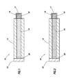
- FIG. 1 is an illustration of an embodiment of a deflagration to detonation transition detonator according to an embodiment of the disclosure.
- FIG. 2 is an illustration of an embodiment of a deflagration to detonation transition detonator according to an embodiment of the disclosure.
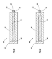
- FIG. 3 is an illustration of an embodiment of a deflagration to detonation transition detonator according to an embodiment of the disclosure.
- FIG. 4 is an illustration of an embodiment of a deflagration to detonation transition detonator according to an embodiment of the disclosure.
- FIG. 5 is an illustration of an embodiment of a deflagration to detonation transition detonator according to an embodiment of the disclosure.
- FIG. 6 is an illustration of an embodiment of a deflagration to detonation transition detonator according to an embodiment of the disclosure.
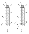
- FIG. 7 is an illustration of an embodiment of a deflagration to detonation transition detonator according to an embodiment of the disclosure.
- FIG. 8 is an illustration of an embodiment of a deflagration to detonation transition detonator according to an embodiment of the disclosure.
- FIG. 9 is an illustration of a composition according to an embodiment of the disclosure.
- FIG. 10 is an illustration of an embodiment of a deflagration to detonation transition detonator according to an embodiment of the disclosure.
- FIG. 11 is an illustration of an embodiment of a deflagration to detonation transition detonator according to an embodiment of the disclosure.
- FIG. 12 is an illustration of an embodiment of a deflagration to detonation transition detonator according to an embodiment of the disclosure.
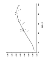
- FIG. 13 is a graph of some preliminary test results.
- the present disclosure teaches a detonator suitable for use in high temperature applications, as well as in other applications, that does not employ primary explosives.
- the detonator may be employed to detonate a detonating cord to fire a perforation gun as part of wellbore completion operations directed to producing hydrocarbons from a subterranean formation.
- downhole temperatures of production zones may exceed 400 degrees Fahrenheit (F) (200 degrees C).
- F degrees Fahrenheit
- Some oilfield provinces are located in nations that are subject to United States export restrictions that constrain the export of detonators that use primary explosives.
- a novel explosive composition taught by the present disclosure may be employed in the detonator taught by the present disclosure.
- the detonator and the explosive composition taught by the present disclosure may be advantageously employed in a wide range of applications, not just in the exemplary embodiment of an oilfield downhole detonator and not just in high temperature applications.
- the detonator taught by the present disclosure may be operated in some high temperature applications where other detonators may not be suitable, the detonator of the present disclosure may also be used successfully in lower temperature environments.
- the detonator is of a deflagration to detonation transition (DDT) detonator type.
- a DDT detonator comprises a pressure containment body that may contain an explosive and an initiator. The initiator activates the explosive in the deflagration mode. As the explosive combusts, and the flame front in the explosive propagates, pressure and temperature increases within the pressure containment body, increasing the stimulus to the explosive until the explosive transitions from the deflagration mode to the detonation mode. While the flame front propagation and the transition from deflagration to detonation occur rapidly in general purpose secondary explosives, in thermally stable secondary explosives the transition from deflagration to detonation may occur relatively more slowly.
- thermally stable secondary explosive refers to a family of secondary explosives that exhibit thermal stability when maintained at a temperature of at least 400 degrees F (200 degrees C) for a time duration of at least one hour.
- Thermal stability means that the explosive does not spontaneously go active at the subject temperature and that the explosive substantially retains its key explosive characteristics at the subject temperature, for example, its characteristic sensitivity and its characteristic energy yield.
- explosives such as, but not limited to, HNS, PYX, Tacot, ONT, BRX, DODECA, and NONA.
- thermally stable secondary explosives may exhibit thermal stability at about 425 degrees F (218 degrees C) for over 100 hours, for example, for about 200 hours.
- thermally stable secondary explosives may exhibit thermal stability at about 450 degrees F (232 degrees C) for at least an hour.
- thermally stable secondary explosives are comprehended by the above definition of a thermally stable explosive, where the subject explosive retains its key explosive characteristics when maintained at a temperature of at least 400 degrees F (200 degrees C) for a time duration of at least one hour.
- the DDT detonator taught by the present disclosure may be referred to as a thermally stable DDT detonator.
- the DDT detonator taught by the present disclosure may be referred to as a high temperature DDT detonator. It is understood, however, that the DDT detonator taught by the present disclosure - whether referred to as a thermally stable DDT detonator or as a high temperature DDT detonator - is not limited to being used in high temperature environments and is not limited to being used in applications that require the use of a thermally stable detonator.
- the thermally stable secondary explosive comprises a mixture of a first thermally stable secondary explosive and a second thermally stable secondary explosive, where the first thermally stable secondary explosive is more sensitive than the second thermally stable secondary explosive, but in another embodiment of the thermally stable DDT detonator, the thermally stable secondary explosive may comprise the first thermally stable secondary explosive substantially unmixed. In some embodiments of the thermally stable DDT detonator, a layer of the first thermally stable secondary explosive unmixed with other explosive material is disposed between the initiator and the mixture of the first and second thermally stable secondary explosives.
- the first thermally stable secondary explosive may comprise at least 10% of the explosive material in the mixture of the first and second thermally stable secondary explosives. In another embodiment of the thermally stable DDT detonator, the first thermally stable secondary explosive may comprise at least 40% of the explosive material in the mixture of the first and second thermally stable secondary explosives. In another embodiment of the thermally stable DDT detonator, the first thermally stable secondary explosive may comprise at least 65% of the explosive material in the mixture of the first and second thermally stable secondary explosives. In another embodiment of the thermally stable DDT detonator, the first thermally stable secondary explosive may comprise between about 75% and 95% of the explosive material in the mixture of the first and second thermally stable secondary explosives.
- the first thermally stable secondary explosive may comprise between about 80% and 90% of the explosive material in the mixture of the first and second thermally stable secondary explosives. In another embodiment of the thermally stable DDT detonator, the first thermally stable secondary explosive may comprise between about 83% and 87% of the explosive material in the mixture of the first and second thermally stable secondary explosives. In other embodiments, yet other proportions may be employed.
- the present disclosure teaches a novel explosive composition that contains effectively no primary explosives and is suitable for use in high temperature applications.
- the composition may include a first layer of a first thermally stable secondary explosive having a first sensitivity, a second layer of a mixture of the first thermally stable secondary explosive and a second thermally stable secondary explosive having a second sensitivity, where the first sensitivity is greater than the second sensitivity, and a packed third layer of the second thermally stable secondary explosive.
- the first thermally stable explosive may be related to NONA and the second thermally stable secondary explosive may be related to HNS.
- the first DDT detonator 10 comprises a first deflagration to detonation transition (DDT) body 12, a first thermally stable secondary explosive 14, a booster assembly 16, an initiator 20, and a bulkhead 22.
- the booster assembly 16 comprises a cup 17 and a packed thermally stable secondary explosive 18.
- the first thermally stable DDT detonator 10 contains effectively no primary explosives.
- the first thermally stable secondary explosive 14 and the packed thermally stable secondary explosive 18 may be defined to exhibit thermal stability at 400 degrees F (200 degrees C) for at least one hour and to be less sensitive than PETN (Pentaerythritol Tetranitrate) explosive.
- the first thermally stable secondary explosive 14 and the packed thermally stable secondary explosive 18 may be defined to exhibit thermal stability at 450 degrees F (232 degrees C) for at least one hour and to be less sensitive than PETN.
- the thermally stable secondary explosive 14 and the packed thermally stable secondary explosive 18 may be defined to exhibit thermal stability at 425 degrees F (218 degrees C) for at least one hundred hours and to be less sensitive than PETN.
- the term sensitive and/or sensitivity refer to responsiveness of an explosive to stimulus. More specifically, the term sensitivity may refer to the readiness of the explosive to be initiated and/or exploded in response to any of an impact shock, friction, shearing force, heat, static electricity, and electrical sparks.
- the first thermally stable secondary explosive 14 and the packed thermally stable secondary explosive 18 may be selected from one of NONA (2,2',2"-4,4',4"-6,6',6"-nonanitroterphenyl), HNS-I (where HNS is generally hexanitrostilbene), HNS-II, HNS-IV, BRX (1,3,5-trinitro-2,4,6-tripicrylbenzene), PYX (picrylaminodimitropyridine), Tacot (Tetranitrobenzotriazolo-benzotriazole), ONT (2,2',4,4',4",6,6',6” Octanitroterpheyl), DODECA (Dodecanitro-m,m'-quatraphenyl), and CL-20 (2,4,6,8,10,12-hexanitrohexaazaisowurtzitane).
- NONA 2,2',2"-4,4',4"-6,6',6"-nonanitroterphenyl
- compositions having similar chemical properties and/or explosive characteristics particularly having similar sensitivity and temperature stability, either existing or developed in the future, could likewise be used.
- Other compositions having similar chemical properties and/or explosive characteristics may be said to be related to these thermally stable secondary explosives.
- the packed thermally stable secondary explosive 18 may be the same explosive as the first thermally stable secondary explosive 14.
- the first thermally stable secondary explosive 14 may be introduced into an interior chamber of the first DDT body 12 in small increments. Between the introductions of small increments of the first thermally stable secondary explosive 14, the first DDT body 12 may be vibrated to promote the elimination of excess air between the particles of the first thermally stable secondary explosive 14.
- the packed thermally stable secondary explosive 18 may be referred to as a pellet of thermally stable secondary explosive.
- the first thermally stable secondary explosive 14 and the packed thermally stable secondary explosive 18 may contain a small portion of non-explosive materials, for example, but not by way of limitation, polymers, waxes, or binders, to promote stability, handling, and/or shaping characteristics.
- the cup 17 may be formed of any material suitable to retain the packed thermally stable secondary explosive 18 and to propagate detonation, for example, to propagate detonation to a detonating cord associated with a perforation gun.
- the cup 17 may be formed of a thin metal material and be coupled to a nipple of the first DDT body 12, for example, by crimping the cup 17 onto the nipple.
- the cup 17 may be formed of ceramic, plastic, threads, cloth, fiberglass, composite materials, or other non-metallic materials and/or coupled to the first DDT body 12 by other known retaining mechanisms, such as, but not limited to, by an adhesive, a rivet, a clip, a screw, a bolt, a pin, a weld, or a laser weld.
- the cup 17 may be coupled to the first DDT body 12 by a snap fit.
- the interior of the cup 17 may have surface irregularities, for example, ridges, stippling, and/or other surface irregularities, to promote adherence of the packed thermally stable secondary explosive 18 in the cup 17.
- the cup 17 may have a variety of shapes and sizes and is not limited by the proportions represented in FIG. 1 .
- the first thermally stable DDT detonator 10 may not comprise the packed thermally stable secondary explosive 18, and the cup 17 may function to close the end of the first DDT body 12 and to retain the first thermally stable secondary explosive 14 within the first DDT body 12 and/or to exclude unwanted materials, for example, but not by way of limitation, wellbore circulation fluid, from the first thermally stable secondary explosive 14.
- the first DDT body 12 may be formed of any high strength material suitable for substantially retaining the pressure generated by activation of the first thermally stable secondary explosive 14, at least until the reaction transitions to the detonation mode.
- the first DDT body 12 may be formed of a metal, such as, but not by way of limitation, steel, or a non-metal, such as, but not by way of limitation, ceramic, plastic, reinforced composite materials, or another high strength material.
- the first DDT body 12 defines the interior chamber that contains the first thermally stable secondary explosive 14 and the initiator 20. It is understood that FIG. 1 is not intended to represent relative dimensions and/or proportions of the first thermally stable DDT detonator 10.
- proportions among the thickness of the wall of the first DDT body 12, the diameter of the chamber defined by the first DDT body 12, and/or the length of the first DDT body 12 may be different from those illustrated in FIG. 1 .
- the first DDT body 12 is about 3 inches long, but in other embodiments the first DDT body 12 may have different lengths.
- the first DDT body 12 is relatively longer than known DDT detonators, based on the first thermally stable secondary explosive 14 being generally less sensitive than explosives employed in known DDT detonators.
- altering the shape of the interior chamber defined by the first DDT body 12, for example, tapering the interior chamber to narrow towards the booster assembly 16, may promote a more rapid transition to the detonation mode and may enable shortening the length of the first DDT body 12.
- the initiator 20 generates a hot flame front to initiate deflagration of the first thermally stable secondary explosive 14.
- the initiator 20 may activate in response to external signals, including a pressure signal, an electrical signal, and/or another type of signal.
- the initiator 20 may activate in response to a percussive impulse, for example, an impact from a firing pin.
- the initiator 20 may activate in response to an electrical current, for example, but not by way of limitation, in response to a surge of current from a charged electrical capacitor.
- the initiator 20 may comprise one of a semiconductor bridge (SCB), a primer, and a percussion cap.
- SCB semiconductor bridge
- the initiator 20 further comprises an energetic material, such as an insensitive pyrotechnic material, in intimate contact with the first thermally stable secondary explosive 14.
- an energetic material such as an insensitive pyrotechnic material
- the term pyrotechnic refers to a material which burns but does not detonate.
- the pyrotechnic material may comprise THKP (titanium hydride potassium perchlorate) pyrotechnic powder, TSPP (titanium subhydride potassium perchlorate) pyrotechnic material, TMAP-KP (tetramethylammonium perchlorate-potassium perchlorate) pyrotechnic material, or another pyrotechnic material.
- THKP titanium hydride potassium perchlorate
- TSPP titanium subhydride potassium perchlorate
- TMAP-KP tetramethylammonium perchlorate-potassium perchlorate
- the bulkhead 22 is coupled to the first DDT body 12 to confine and enhance pressure build-up during the deflagration to detonation transition.
- the bulkhead 22 may be referred to as a plug or a cap.
- the bulkhead 22 may be coupled to the first DDT body 12 by one of screws, bolts, rivets, adhesives, a locking ring, an interference fit, a snap fit, pins, and other like attaching hardware.
- the bulkhead 22 may be coupled to the first DDT body 12 by threaded engagement between a threading of the bulkhead 22 and a thread of the first DDT body 12.
- the bulkhead 22 may be coupled to the first DDT body 12 by welding and/or spot welding.
- the bulkhead 22 may be coupled to the first DDT body 12 by fusing together some of the material of the bulkhead 22 with some of the material of the first DDT body 12, for example, using a laser welder and/or an ultrasound process.
- the bulkhead 22 need no longer remain coupled to the first DDT body 12, because once detonation has been achieved in the first thermally stable secondary explosive 14 the detonation may continue to propagate independently of the bulkhead 22 confining and enhancing pressure build-up.
- the bulkhead 22 may rupture or the coupling of the bulkhead 22 to the first DDT body 12 may fail after detonation of the first thermally stable secondary explosive 14 is achieved.
- the bulkhead 22 and the coupling of the bulkhead 22 to the first DDT body 12 are designed to contain pressure substantially within the interior chamber after activation of the first thermally stable secondary explosive 14 and until the deflagration to detonation transition occurs.
- the bulkhead 22 and the coupling are designed to contain pressure substantially within the interior chamber for at least 0.5 microsecond (500 nanoseconds) after activation of the first thermally stable secondary explosive 14. In an embodiment, the bulkhead 22 and the coupling are designed to contain pressure substantially within the interior chamber for at least 1 microsecond after activation of the first thermally stable secondary explosive 14. In an embodiment, the bulkhead 22 and the coupling are designed to contain pressure substantially within the interior chamber for at least 10 microseconds after activation of the first thermally stable secondary explosive 14. In an embodiment, the bulkhead 22 and the coupling are designed to contain pressure substantially within the interior chamber for at least 100 microseconds after activation of the first thermally stable secondary explosive 14.
- the bulkhead 22 and the coupling are designed to contain pressure substantially within the interior chamber for at least 1 millisecond after activation of the first thermally stable secondary explosive 14.
- the bulkhead 22 and the coupling are designed to withstand a pressure of at least 50 pounds per square inch (PSI) (340 kPa) applied to the bulkhead 22.
- PSI pounds per square inch
- the bulkhead 22 and the coupling are designed to withstand a pressure of at least 100 PSI (690 kPa) applied to the bulkhead 22.
- the bulkhead 22 and the coupling are designed to withstand a pressure of at least 200 PSI (1400 kPa) applied to the bulkhead 22.
- the bulkhead 22 and the coupling are designed to withstand a pressure of at least 500 PSI (3400 kPa) applied to the bulkhead 22. In an embodiment, the bulkhead 22 and the coupling are designed to withstand a pressure of at least 1000 PSI (6900 kPa) applied to the bulkhead 22. In an embodiment, the bulkhead 22 and the coupling are designed to withstand a pressure of at least 5000 PSI (34 MPa) applied to the bulkhead 22. In an embodiment, the bulkhead 22 and the coupling are designed to withstand a pressure of at least 10000 PSI (69 MPa) applied to the bulkhead 22.
- the second thermally stable DDT detonator 40 is substantially similar to the first thermally stable DDT detonator 10 described above, with the exception that rather than the first thermally stable secondary explosive 14, the first DDT body 12 contains a mixture of two different thermally stable secondary explosives 42.
- the second thermally stable DDT detonator 40 contains effectively no primary explosives.
- the mixture of explosives 42 may be introduced into the interior chamber in small increments. Between the introductions of small increments of the mixture of explosives 42, the first DDT body 12 may be vibrated to promote the elimination of excess air between the particles of the mixture of explosives 42.
- the mixture of explosives 42 may comprise a second thermally stable secondary explosive and a third thermally stable secondary explosive.
- the second thermally stable secondary explosive and the third thermally stable secondary explosive may be defined to exhibit thermal stability at 400 degrees F (200 degrees C) for at least one hour and to be less sensitive than PETN explosive.
- the second thermally stable secondary explosive and the third thermally stable secondary explosive may be defined to exhibit thermal stability at 450 degrees F (232 degrees C) for at least one hour and to be less sensitive than PETN. In another embodiment, the second thermally stable secondary explosive and the third thermally stable secondary explosive may be defined to exhibit thermal stability at 425 degrees F (218 degrees C) for at least one hundred hours and to be less sensitive than PETN.
- the second thermally stable secondary explosive may comprise from 10% to 98% of the mixture of explosives 42. In another embodiment, the second thermally stable secondary explosive may comprise from 65% to 98% of the mixture of explosives 42. In another embodiment, the second thermally stable secondary explosive may comprise from 75% to 95% of the mixture of the explosives 42. In another embodiment, the second thermally stable secondary explosive may comprise 80% to 90% of the mixture of the explosives 42. In another embodiment, the second thermally stable secondary explosive may comprise 83% to 87% of the mixture of the explosives 42. In an embodiment, the second thermally stable secondary explosive comprises NONA or an explosive related to NONA. In an embodiment, the third thermally stable secondary explosive comprises HNS-I, HNS-II and/or HNS-IV. In an embodiment, the third thermally stable secondary explosive comprises an explosive related to HNS-I, HNS-II, and/or HNS-IV.
- the third thermally stable DDT detonator 50 is substantially similar to either the first thermally stable DDT detonator 10 or the second thermally stable DDT detonator 40, with the exception that an interior chamber defined by a second DDT body 52 tapers, narrowing towards a second booster assembly 54.
- the second booster assembly 54 may comprise a second cap 56 and the packed thermally stable secondary explosive 18.
- the third thermally stable DDT detonator 40 may not include the packed thermally stable secondary explosive 18, and the second cap 56 may be employed to retain the explosives within the second DDT body 52 and/or to exclude unwanted materials, such as wellbore circulation fluid, from the explosives.
- the tapered contour of the interior chamber of the second DDT body 52 may promote more rapid transition from deflagration mode to detonation mode and permit reducing the length of the third thermally stable DDT detonator 50.
- the interior chamber of the second DDT body 52 tapers throughout the entire region containing the first thermally stable secondary explosive 14 or the mixture of explosives 42.
- the taper may be linear.
- the taper may be curved, for example, parabolic, the taper may be stair-stepped, or the taper may have a different geometry.
- the third thermally stable DDT detonator 50 contains effectively no primary explosives.
- the fourth thermally stable DDT detonator 60 is substantially similar to the third thermally stable DDT detonator 50, with the exception that an interior chamber defined by a third DDT body 62 tapers only over a portion of the interior chamber proximate to the second booster assembly 54, for example, over the third of the interior chamber proximate to the second booster assembly 54, over a fourth of the interior chamber proximate to the second booster assembly 54, or over some other fraction of the interior chamber effective to promote more rapid transition from the deflagration mode to the detonation mode.
- the fourth thermally stable DDT detonator 60 may not include the packed thermally stable secondary explosive 18, and the second cap 56 may be employed to retain the explosives within the third DDT body 62 and/or to exclude unwanted materials, such as wellbore circulation fluid, from the explosives.
- the taper of the interior chamber may be linear, curved, stair-stepped, or have some other geometry.
- the fourth thermally stable DDT detonator 60 may contain one of the first thermally stable secondary explosive 14 and the mixture of two different thermally stable secondary explosives 42.
- the fourth thermally stable DDT detonator 60 contains effectively no primary explosives.
- the fifth thermally stable DDT detonator 70 is substantially similar to the second thermally stable DDT detonator 40, with the exception that a layer of the unmixed second thermally stable secondary explosive 72 is disposed between the initiator 20 and the mixture of explosives 42.
- the fifth thermally stable DDT detonator 70 contains effectively no primary explosives.
- the sixth thermally stable DDT detonator 80 is substantially similar to the first thermally stable DDT detonator 10, with the exception that the pressure retention functionality of the bulkhead 22 is provided instead by a subassembly 82 coupled to the sixth thermally stable DDT detonator 80, for example, threadingly coupled to the sixth thermally stable DDT detonator 80.
- a mechanical structure or extension may project from the subassembly 82 to prop and/or support the initiator 20.
- the sixth thermally stable DDT detonator 80 may contain the mixture of explosives 42 rather than the first thermally stable secondary explosive 14.
- the sixth thermally stable DDT detonator 80 contains effectively no primary explosives.
- the seventh thermally stable DDT detonator 90 is substantially similar to the first thermally stable DDT detonator 10, with the exception that a fourth DDT body 92 of the seventh thermally stable DDT detonator 90 is substantially closed at an initiator end, thereby avoiding the use of the bulkhead 22.
- the initiator end of the fourth DDT body 92 may have one or more apertures to promote communication with the initiator 20, for example, to allow an electrical connection to the initiator 20 or to allow a firing pin to strike a primer or percussion cap of the initiator 20.
- the seventh thermally stable DDT detonator 90 may contain the mixture of explosives 42 rather than the first thermally stable secondary explosive 14.
- the seventh thermally stable DDT detonator 90 contains effectively no primary explosives.
- the eighth thermally stable DDT detonator 96 is substantially similar to the fifth thermally stable DDT detonator 70, with the addition of a layer of pyrotechnic material 98 between the initiator 20 and the layer of the unmixed second thermally stable secondary explosive 72.
- the pyrotechnic material 98 is not an explosive and burns without detonating.
- the pyrotechnic material 98 is selected to burn at a high temperature, thereby more reliably activating the layer of the unmixed second thermally stable secondary explosive 72.
- the pyrotechnic material 98 may be one of THKP, TSSP, TMAP-KP, or another pyrotechnic material.
- the eighth thermally stable DDT detonator 96 contains effectively no primary explosives.
- the thermally stable DDT detonator is said to contain "effectively no primary explosives" to provide for the possibility that some minute and unintentional quantities of primary explosives may be found in the secondary explosives.
- Such trace amounts of primary explosives may unintentionally infiltrate the secondary explosives by a variety of circumstances, some examples of which are described following.
- the primary explosives may be present as an unintended impurity of the manufacturing process, the depot handling process, and/or the field handling process.
- an inconsiderable quantity of primary explosive may infiltrate the thermally stable DDT detonator by contamination from tooling or from the ambient manufacturing environment or from handling in a depot that includes other detonator devices that contain primary explosives.
- a small amount of primary explosive may be present in a quantity that is insufficient to trigger transportation and/or export regulations directed to primary explosives.
- a small quantity of primary explosive - less than the quantity that invokes application of transportation and/or export regulations related to primary explosives - may be mixed into the thermally stable secondary explosive proximate to the booster assembly 16 to assure the transition from deflagration to detonation in worst case circumstances and thereby enhance the reliability of the thermally stable DDT detonator.
- a small quantity of primary explosive for example, but not by way of limitation, such as lead azide and/or silver azide, may be present in the initiator 20. In effect, the inclusion of such small quantities of primary explosives does not substantively change the novel principle of operation and the novel structure taught by the present disclosure.
- the composition 100 comprises a first layer of mixed thermally stable secondary explosives 102, a second layer of a packed thermally stable secondary explosive 104, and a third layer of unmixed thermally stable secondary explosive 106.
- the first layer 102 comprises a mixture of two or more thermally stable secondary explosives selected from the list comprising NONA, HNS-I, HNS-II, HNS-IV, BRX, PYX, Tacot, ONT, DODECA, and CL-20.
- the first layer 102 comprises a mixture of HNS-II and NONA.
- the first layer 102 comprises a mixture of HNS-II, HNS-lV, and NONA. In an embodiment, the first layer 102 comprises a mixture of NONA and one or more of HNS-I, HNS-II and HNS-IV, wherein the NONA comprises from 10% to 98% of the mixture. In an embodiment, the first layer 102 comprises a mixture of NONA and one or more of HNS-I, HNS-II and HNS-IV, wherein the NONA comprises from 10% to 98% of the mixture. In another embodiment, the first layer 102 comprises a mixture of NONA and one or more of HNS-I, HNS-II and HNS-lV, wherein the NONA comprises from 40% to 98% of the mixture.
- the first layer 102 comprises a mixture of NONA and one or more of HNS-I, HNS-II and HNS-IV, wherein the NONA comprises from 65% to 98% of the mixture. In another embodiment, the first layer 102 comprises a mixture of NONA and one or more of HNS-I, HNS-II and HNS-lV, wherein the NONA comprises from 75% to 95% of the mixture. In another embodiment, the first layer 102 comprises a mixture of NONA and one or more of HNS-I, HNS-II and HNS-lV, wherein the NONA comprises from 80% to 90% of the mixture.
- the first layer 102 comprises a mixture of NONA and one or more of HNS-I, HNS-II and HNS-lV, wherein the NONA comprises from 83% to 87% of the mixture.
- the second layer 104 comprises packed HNS explosive, for example, one or more of HNS-I, HNS-II and HNS-IV.
- the third layer 106 comprises unmixed explosive from the list comprising NONA, HNS-I, HNS-II, HNS-lV, BRX, PYX, Tacot, ONT, DODECA, and CL-20.
- thermally stable secondary explosives having similar chemical properties and/or explosive characteristics may be substituted for the NONA, HNS-I, HNS-II, and HNS-IV explosives above.
- a first thermally stable secondary explosive having a sensitivity about like that of NONA and having about the same amount of maximum power per unit volume as NONA may be substituted for NONA.
- a second thermally stable secondary explosive having a sensitivity about like that of HNS-I, HNS-II and/or HNS-IV and having about the same amount of maximum power per unit volume as HSN-I, HNS-II and/or HNS-lV may be substituted for HNS-I, HNS-II and/or HNS-IV. It is thought that using a more sensitive thermally stable secondary explosive in the third layer 106 promotes better initiation of the composition 100.
- the composition 100 may be employed in combination with the thermally stable DDT detonator described in more detail above.
- the composition 100 may have applications in other structures and apparatuses.
- the composition 100 may be used in other shapes.
- the interfaces between the layers is illustrated as substantially straight, in another embodiment the interfaces between the layers may be curved or combinations of intersecting planes or non-planar.
- a delay element may be introduced into any of the embodiments of the thermally stable DDT detonator described above.
- an initiator and/or a pyrotechnic initiates a burning reaction in a delay column formed of a combustible material, such as, but not by way of limitation, a compacted tungsten powder or a tungsten powder mixture.
- this delay column may be referred to as a fuse or as providing functionality similar to that of a fuse.
- the delay column burns, effecting a delay, until it reaches the secondary explosive mixture which then initiates and begins the deflagration to detonation reaction, as described above.
- the ninth thermally stable DDT detonator 120 is substantially similar to the second thermally stable DDT detonator 40 described above, with the exception that a delay column 122 is placed between the initiator 20 and the mixture of two different thermally stable secondary explosives 42.
- the delay column 122 may also be referred to as combustible fuse material.
- the delay column 122 may be comprised of tungsten powder, compacted tungsten powder, or other materials effective to propagate a flame front at a reduced rate relative to the flame front propagation rate in the secondary explosives 42.
- the tenth thermally stable DDT detonator 130 is substantially similar to the second thermally stable DDT detonator 40 described above, with the exception that the tenth thermally stable DDT detonator 130 comprises a fourth DDT body 132 that is open at a bulkhead end and closed at a packed thermally stable secondary explosive end.
- the wall thickness of the fourth DDT body 132 may be thinner at the packed thermally stable secondary explosive end than along the sides containing the mixture of explosives 42.
- the wall thickness of the fourth DDT body 132 may be substantially the same at packed thermally stable secondary explosive end as the wall thickness along the sides containing the mixture of explosives 42.
- the packed thermally stable secondary explosive 18 is first introduced into the open end of the fourth DDT body 132 and then packed into the closed end of the fourth DDT body 132.
- the mixture of explosives 42 is introduced into the open end of the fourth DDT body 132.
- the initiator 20 is installed.
- the bulkhead 22 is coupled to the fourth DDT body 132 to complete the assembly of the tenth thermally stable DDT detonator 130.
- the closed end of the fourth DDT body 132 may promote sealing the tenth thermally stable DDT detonator 130 from undesired contact with fluids and/or pressures in the downhole environment. Additionally, in some embodiments, the closed end of the fourth DDT body 132 may protect the components of the tenth thermally stable DDT detonator 130, for example, the packed thermally stable secondary explosive 18, from mechanical hazards.
- the eleventh thermally stable DDT detonator 136 is substantially similar to the tenth thermally stable DDT detonator 130, with the difference that the eleventh thermally stable DDT detonator 136 does not include the packed thermally stable secondary explosive 18.
- the packed thermally stable secondary explosive 18 of other embodiments may boost or amplify the amplitude of the detonation, but it is thought that, at least in some embodiments, such as in the eleventh thermally stable DDT detonator 136, the objective of propagating a detonation, for example, to a detonator cord in a perforation gun, may be achieved without the use of the packed thermally stable secondary explosive 18.
- the fourth DDT body 132 may be combined with other embodiments and configurations of thermally stable DDT detonators described above.
- the mixture of explosives 42 contained in the tenth thermally stable DDT detonator 130 and/or in the eleventh thermally stable DDT detonator 136 may be replaced with the first thermally stable secondary explosive 14 of the first thermally stable DDT detonator 10.
- the tapered interior chamber of the DDT body described in the third thermally stable DDT detonator 50 and/or the fourth thermally stable DDT detonator 60 may be combined with the tenth thermally stable DDT detonator 130 and/or in the eleventh thermally stable DDT detonator 136.
- the tenth thermally stable DDT detonator 130 and/or the eleventh thermally stable DDT detonator 136 may comprise a layer of the unmixed second thermally stable secondary explosive 72 disposed between the initiator 20 and the mixture of explosives 42.
- the subassembly 82 described above with reference to FIG. 6 may replace the bulkhead 22 in the tenth thermally stable DDT detonator 130 and/or the eleventh thermally stable DDT detonator 136.
- the tenth thermally stable DDT detonator 130 and/or the eleventh thermally stable DDT detonator 136 may comprise a layer of pyrotechnic material 98 between the initiator 20 and the mixed secondary explosive 42 or the layer of unmixed secondary explosive 72.
- the tenth thermally stable DDT detonator 130 and/or the eleventh thermally stable DDT detonator 136 may comprise a delay column 122 as described above with reference to FIG. 10 .
- the horizontal axis of the chart depicted in FIG. 13 corresponds to the percentage of NONA secondary explosive in a mixture with HNS secondary explosive in the thermally stable DDT detonator, and the range of values represented on the horizontal axis is from 0% to 100%.
- the vertical axis of the chart depicted in FIG. 13 corresponds to inches of swell of the diameter of a detonation end of the thermally stable DDT detonator after detonation.
- the detonation end of the thermally stable DDT detonator may be opposite an initiator end of the thermally stable DDT detonator.
- the individual points on FIG. 13 represent specific tests conducted.
- the continuous curve represents the data points smoothed to fit a third order polynomial equation.
- the graph in FIG. 13 suggests that a mixture comprising at least 40% NONA secondary explosive can produce desirable detonation results. Further, the graph in FIG. 13 suggests that the detonation results improve as the percentage of NONA secondary explosive in the mixture is increased to at least 65% of the mixture. While the data points and the third order polynomial curve indicate an optimum mixture in the range of about 80% to 90% NONA secondary explosive mixed with HNS secondary explosive, this interpretation should be tempered by appreciation for the limited number of tests performed.
- the third order polynomial curve suggests an optimum mixture in the range of 83% to 87% NONA secondary explosive mixed with HNS secondary explosive, but the use of other mixture ratios of NONA secondary explosive to HNS secondary explosive in the thermally stable DDT detonator are contemplated by the present disclosure.
Landscapes
- Engineering & Computer Science (AREA)
- General Engineering & Computer Science (AREA)
- Chemical & Material Sciences (AREA)
- Organic Chemistry (AREA)
- Chemical Kinetics & Catalysis (AREA)
- General Chemical & Material Sciences (AREA)
- Air Bags (AREA)
- Fodder In General (AREA)
- Agricultural Chemicals And Associated Chemicals (AREA)
- Medicinal Preparation (AREA)
Priority Applications (1)
| Application Number | Priority Date | Filing Date | Title |
|---|---|---|---|
| EP15168772.0A EP2942599A3 (fr) | 2009-12-21 | 2010-12-20 | Dispositif de transition de déflagration à détonation |
Applications Claiming Priority (1)
| Application Number | Priority Date | Filing Date | Title |
|---|---|---|---|
| US12/643,988 US8161880B2 (en) | 2009-12-21 | 2009-12-21 | Deflagration to detonation transition device |
Related Child Applications (2)
| Application Number | Title | Priority Date | Filing Date |
|---|---|---|---|
| EP15168772.0A Division EP2942599A3 (fr) | 2009-12-21 | 2010-12-20 | Dispositif de transition de déflagration à détonation |
| EP15168772.0A Division-Into EP2942599A3 (fr) | 2009-12-21 | 2010-12-20 | Dispositif de transition de déflagration à détonation |
Publications (2)
| Publication Number | Publication Date |
|---|---|
| EP2336710A2 true EP2336710A2 (fr) | 2011-06-22 |
| EP2336710A3 EP2336710A3 (fr) | 2015-07-08 |
Family
ID=43498605
Family Applications (2)
| Application Number | Title | Priority Date | Filing Date |
|---|---|---|---|
| EP15168772.0A Withdrawn EP2942599A3 (fr) | 2009-12-21 | 2010-12-20 | Dispositif de transition de déflagration à détonation |
| EP10196047.4A Withdrawn EP2336710A3 (fr) | 2009-12-21 | 2010-12-20 | Dispositif de transition de déflagration à détonation |
Family Applications Before (1)
| Application Number | Title | Priority Date | Filing Date |
|---|---|---|---|
| EP15168772.0A Withdrawn EP2942599A3 (fr) | 2009-12-21 | 2010-12-20 | Dispositif de transition de déflagration à détonation |
Country Status (2)
| Country | Link |
|---|---|
| US (3) | US8161880B2 (fr) |
| EP (2) | EP2942599A3 (fr) |
Cited By (4)
| Publication number | Priority date | Publication date | Assignee | Title |
|---|---|---|---|---|
| WO2014080139A1 (fr) * | 2012-11-23 | 2014-05-30 | Nexter Munitions | Composant generateur de gaz pyrotechnique |
| CN104634192A (zh) * | 2015-01-09 | 2015-05-20 | 西安近代化学研究所 | 一种用于测定发射药燃烧转爆轰性能的试验装置 |
| EP3002542B1 (fr) * | 2014-10-01 | 2018-04-04 | TDW Gesellschaft für verteidigungstechnische Wirksysteme mbH | Dispositif de formation de fragmentation a l'aide de charges rainurees pouvant etre activees par temperature |
| WO2024133607A1 (fr) * | 2022-12-22 | 2024-06-27 | DynaEnergetics Europe GmbH | Détonateur libre primaire |
Families Citing this family (10)
| Publication number | Priority date | Publication date | Assignee | Title |
|---|---|---|---|---|
| AU2008229625B2 (en) * | 2007-03-16 | 2012-06-14 | Orica Explosives Technology Pty Ltd | Initiation of explosives materials |
| US8161880B2 (en) | 2009-12-21 | 2012-04-24 | Halliburton Energy Services, Inc. | Deflagration to detonation transition device |
| US8776689B2 (en) * | 2011-03-25 | 2014-07-15 | Vincent Gonsalves | Energetics train reaction and method of making an intensive munitions detonator |
| WO2014123508A1 (fr) * | 2013-02-05 | 2014-08-14 | Halliburton Energy Energy Services, Inc. | Initiateur présentant une substance explosive d'un explosif secondaire |
| US10490054B2 (en) | 2013-12-26 | 2019-11-26 | Halliburton Energy Services, Inc. | In-line integrity checker |
| WO2015126375A1 (fr) * | 2014-02-19 | 2015-08-27 | Halliburton Energy Services, Inc. | Explosifs de co-cristal pour des opérations de fond de trou à haute température |
| SE539175C2 (en) * | 2015-10-05 | 2017-05-02 | Life Time Eng Ab | Detonator provided with a securing device |
| US10760887B2 (en) * | 2016-05-12 | 2020-09-01 | Goodrich Corporation | Detonation transfer assembly |
| US11761743B2 (en) | 2020-05-20 | 2023-09-19 | DynaEnergetics Europe GmbH | Low voltage primary free detonator |
| US12371960B1 (en) | 2024-01-31 | 2025-07-29 | Baker Hughes Oilfield Operations Llc | Field assembled initiator |
Family Cites Families (24)
| Publication number | Priority date | Publication date | Assignee | Title |
|---|---|---|---|---|
| FR1337225A (fr) * | 1961-11-24 | 1963-09-13 | Schlumberger Prospection | Perfectionnements aux dispositifs d'amorçage des cordeaux détonants |
| US4316412A (en) * | 1979-06-05 | 1982-02-23 | The United States Of America As Represented By The United States Department Of Energy | Low voltage nonprimary explosive detonator |
| SE462391B (sv) * | 1984-08-23 | 1990-06-18 | China Met Imp Exp Shougang | Spraengkapsel och initieringselement innehaallande icke-primaerspraengaemne |
| US4616566A (en) * | 1984-10-05 | 1986-10-14 | Halliburton Company | Secondary high explosive booster, and method of making and method of using same |
| US4735145A (en) * | 1987-03-02 | 1988-04-05 | The United States Of America As Represented By The United States Department Of Energy | High temperature detonator |
| EP0289184B1 (fr) * | 1987-04-30 | 1991-12-27 | Nippon Oil And Fats Company, Limited | Détonateur activable par le faisceau d'un laser |
| US4759291A (en) * | 1987-07-06 | 1988-07-26 | Halliburton Company | Through bulkhead explosive initiator for oil well usage |
| US4777878A (en) * | 1987-09-14 | 1988-10-18 | Halliburton Company | Exploding bridge wire detonator with shock reflector for oil well usage |
| US4920883A (en) * | 1989-01-27 | 1990-05-01 | Halliburton Logging Services, Inc. | Detonation transfer methods and apparatus |
| US4998477A (en) * | 1990-02-14 | 1991-03-12 | Halliburton Logging Services, Inc. | Detonation transfer apparatus for initiating detonation of an insensitive detonating cord utilizing an initiating compound, flyer and shock reflector |
| US6053111A (en) * | 1996-07-23 | 2000-04-25 | Halliburton Energy Services, Inc. | Surface safe rig environment detonator |
| US5889228A (en) * | 1997-04-09 | 1999-03-30 | The Ensign-Bickford Company | Detonator with loosely packed ignition charge and method of assembly |
| AU8148098A (en) * | 1997-06-30 | 1999-01-19 | Ensign-Bickford Company, The | Laser-ignitable ignition composition and initiator devices and assemblies comprising the same |
| WO1999053263A2 (fr) * | 1998-01-29 | 1999-10-21 | Halliburton Energy Services, Inc. | Etranglement pour transformer une deflagration en detonation |
| SE516812C2 (sv) * | 1999-09-06 | 2002-03-05 | Dyno Nobel Sweden Ab | Sprängkapsel, förfarande för tändning av basladdning samt initieringselement för sprängkapsel |
| US6435095B1 (en) * | 2000-08-09 | 2002-08-20 | Mccormick Selph, Inc. | Linear ignition system |
| US20020129940A1 (en) * | 2000-12-13 | 2002-09-19 | Wenbo Yang | High temperature explosives for downhole well applications |
| US7343860B2 (en) * | 2005-02-28 | 2008-03-18 | Lockheed Martin Corporation | Safe and arm device and explosive device incorporating safe and arm device |
| US8042471B2 (en) * | 2005-02-28 | 2011-10-25 | Lockheed Martin Corporation | Safe and arm device and explosive device incorporating same |
| FR2888234B1 (fr) * | 2005-07-05 | 2008-05-02 | Saint Louis Inst | Composition energetique dopee optiquement |
| US7430963B2 (en) * | 2005-11-29 | 2008-10-07 | Reynolds Systems, Inc. | Energetic material initiation device utilizing exploding foil initiated ignition system with secondary explosive material |
| US7987787B1 (en) * | 2007-03-07 | 2011-08-02 | Ensign-Bickford Aerospace & Defense Company | Electronic ignition safety device configured to reject signals below a predetermined ‘all-fire voltage’ |
| AU2008229625B2 (en) * | 2007-03-16 | 2012-06-14 | Orica Explosives Technology Pty Ltd | Initiation of explosives materials |
| US8161880B2 (en) | 2009-12-21 | 2012-04-24 | Halliburton Energy Services, Inc. | Deflagration to detonation transition device |
-
2009
- 2009-12-21 US US12/643,988 patent/US8161880B2/en active Active
-
2010
- 2010-12-20 EP EP15168772.0A patent/EP2942599A3/fr not_active Withdrawn
- 2010-12-20 EP EP10196047.4A patent/EP2336710A3/fr not_active Withdrawn
-
2012
- 2012-01-23 US US13/356,619 patent/US8286555B2/en active Active
- 2012-01-23 US US13/356,625 patent/US8291826B2/en active Active
Non-Patent Citations (1)
| Title |
|---|
| None |
Cited By (7)
| Publication number | Priority date | Publication date | Assignee | Title |
|---|---|---|---|---|
| WO2014080139A1 (fr) * | 2012-11-23 | 2014-05-30 | Nexter Munitions | Composant generateur de gaz pyrotechnique |
| FR2998566A1 (fr) * | 2012-11-23 | 2014-05-30 | Nexter Munitions | Composant generateur de gaz pyrotechnique |
| US9574856B2 (en) | 2012-11-23 | 2017-02-21 | Nexter Munitions | Pyrotechnic gas generator component |
| EP3002542B1 (fr) * | 2014-10-01 | 2018-04-04 | TDW Gesellschaft für verteidigungstechnische Wirksysteme mbH | Dispositif de formation de fragmentation a l'aide de charges rainurees pouvant etre activees par temperature |
| US9982979B2 (en) | 2014-10-01 | 2018-05-29 | TDW Gesellschaft fuer verteidgungstechnische Wirksysteme mbH | Device and method for controlled fragmentation by means of temperature-activatable notch charges |
| CN104634192A (zh) * | 2015-01-09 | 2015-05-20 | 西安近代化学研究所 | 一种用于测定发射药燃烧转爆轰性能的试验装置 |
| WO2024133607A1 (fr) * | 2022-12-22 | 2024-06-27 | DynaEnergetics Europe GmbH | Détonateur libre primaire |
Also Published As
| Publication number | Publication date |
|---|---|
| US8286555B2 (en) | 2012-10-16 |
| US8291826B2 (en) | 2012-10-23 |
| US8161880B2 (en) | 2012-04-24 |
| EP2942599A3 (fr) | 2015-12-16 |
| EP2942599A2 (fr) | 2015-11-11 |
| EP2336710A3 (fr) | 2015-07-08 |
| US20110146517A1 (en) | 2011-06-23 |
| US20120118447A1 (en) | 2012-05-17 |
| US20120118191A1 (en) | 2012-05-17 |
Similar Documents
| Publication | Publication Date | Title |
|---|---|---|
| US8161880B2 (en) | Deflagration to detonation transition device | |
| AU2012326644B2 (en) | Explosive pellet | |
| US4144814A (en) | Delay detonator device | |
| US6539869B2 (en) | Heat transfer initiator | |
| US3238876A (en) | Method for through-bulkhead shock initiation | |
| US10094190B2 (en) | Downhole severing tools employing a two-stage energizing material and methods for use thereof | |
| SK587989A3 (en) | An initiating element | |
| US3062143A (en) | Detonator | |
| US4239004A (en) | Delay detonator device | |
| CN101825419A (zh) | 多级变截面激发装置及应用该装置的雷管 | |
| US8226782B2 (en) | Application of high temperature explosive to downhole use | |
| US20110239889A1 (en) | Detonation to igniter booster device | |
| CN106152886A (zh) | 工业飞片雷管及其飞片激发装置 | |
| US20110283872A1 (en) | Downhole severing tool | |
| US7546805B2 (en) | Detonator | |
| Jang et al. | On Design and Performance Simulation of Through Bulkhead Initiators | |
| WO2000026603A1 (fr) | Detonateurs non-primaires | |
| WO1999053263A2 (fr) | Etranglement pour transformer une deflagration en detonation | |
| KR20180127271A (ko) | 3s뇌관 | |
| EP3497399A1 (fr) | Procédé et cartouche de désarmement d'une charge de sautage non explosée dans un trou de forage | |
| CA2252353C (fr) | Detonateur autre que d'amorcage | |
| US3971322A (en) | Pressure actuated tube primer | |
| US3236317A (en) | Projectile propelling apparatus for use in high temperature environment | |
| Warchoł et al. | FACTORS AFFECTING THE OPERATING PARAMETERS OF PYROTECHNIC DELAY DEVICES | |
| CN110926274A (zh) | 一种安全起爆件 |
Legal Events
| Date | Code | Title | Description |
|---|---|---|---|
| PUAI | Public reference made under article 153(3) epc to a published international application that has entered the european phase |
Free format text: ORIGINAL CODE: 0009012 |
|
| AK | Designated contracting states |
Kind code of ref document: A2 Designated state(s): AL AT BE BG CH CY CZ DE DK EE ES FI FR GB GR HR HU IE IS IT LI LT LU LV MC MK MT NL NO PL PT RO RS SE SI SK SM TR |
|
| AX | Request for extension of the european patent |
Extension state: BA ME |
|
| RIC1 | Information provided on ipc code assigned before grant |
Ipc: F42D 1/04 20060101ALN20150212BHEP Ipc: F42C 19/08 20060101ALI20150212BHEP Ipc: F42B 3/10 20060101AFI20150212BHEP |
|
| PUAL | Search report despatched |
Free format text: ORIGINAL CODE: 0009013 |
|
| AK | Designated contracting states |
Kind code of ref document: A3 Designated state(s): AL AT BE BG CH CY CZ DE DK EE ES FI FR GB GR HR HU IE IS IT LI LT LU LV MC MK MT NL NO PL PT RO RS SE SI SK SM TR |
|
| AX | Request for extension of the european patent |
Extension state: BA ME |
|
| RIC1 | Information provided on ipc code assigned before grant |
Ipc: F42B 3/10 20060101AFI20150603BHEP Ipc: F42C 19/08 20060101ALI20150603BHEP Ipc: F42D 1/04 20060101ALN20150603BHEP |
|
| RIN1 | Information on inventor provided before grant (corrected) |
Inventor name: WUENSCHE, THOMAS J. Inventor name: BARKER, JAMES Inventor name: MORITZ, GAYLE |
|
| STAA | Information on the status of an ep patent application or granted ep patent |
Free format text: STATUS: THE APPLICATION IS DEEMED TO BE WITHDRAWN |
|
| 18D | Application deemed to be withdrawn |
Effective date: 20160109 |