EP2336721A1 - Fehlererkennungsverfahren - Google Patents
Fehlererkennungsverfahren Download PDFInfo
- Publication number
- EP2336721A1 EP2336721A1 EP09015817A EP09015817A EP2336721A1 EP 2336721 A1 EP2336721 A1 EP 2336721A1 EP 09015817 A EP09015817 A EP 09015817A EP 09015817 A EP09015817 A EP 09015817A EP 2336721 A1 EP2336721 A1 EP 2336721A1
- Authority
- EP
- European Patent Office
- Prior art keywords
- velocity
- unaided
- measurement
- measurements
- estimate
- Prior art date
- Legal status (The legal status is an assumption and is not a legal conclusion. Google has not performed a legal analysis and makes no representation as to the accuracy of the status listed.)
- Withdrawn
Links
Images




Classifications
-
- G—PHYSICS
- G01—MEASURING; TESTING
- G01C—MEASURING DISTANCES, LEVELS OR BEARINGS; SURVEYING; NAVIGATION; GYROSCOPIC INSTRUMENTS; PHOTOGRAMMETRY OR VIDEOGRAMMETRY
- G01C21/00—Navigation; Navigational instruments not provided for in groups G01C1/00 - G01C19/00
- G01C21/10—Navigation; Navigational instruments not provided for in groups G01C1/00 - G01C19/00 by using measurements of speed or acceleration
- G01C21/12—Navigation; Navigational instruments not provided for in groups G01C1/00 - G01C19/00 by using measurements of speed or acceleration executed aboard the object being navigated; Dead reckoning
- G01C21/16—Navigation; Navigational instruments not provided for in groups G01C1/00 - G01C19/00 by using measurements of speed or acceleration executed aboard the object being navigated; Dead reckoning by integrating acceleration or speed, i.e. inertial navigation
- G01C21/183—Compensation of inertial measurements, e.g. for temperature effects
- G01C21/188—Compensation of inertial measurements, e.g. for temperature effects for accumulated errors, e.g. by coupling inertial systems with absolute positioning systems
-
- G—PHYSICS
- G01—MEASURING; TESTING
- G01S—RADIO DIRECTION-FINDING; RADIO NAVIGATION; DETERMINING DISTANCE OR VELOCITY BY USE OF RADIO WAVES; LOCATING OR PRESENCE-DETECTING BY USE OF THE REFLECTION OR RERADIATION OF RADIO WAVES; ANALOGOUS ARRANGEMENTS USING OTHER WAVES
- G01S19/00—Satellite radio beacon positioning systems; Determining position, velocity or attitude using signals transmitted by such systems
- G01S19/01—Satellite radio beacon positioning systems transmitting time-stamped messages, e.g. GPS [Global Positioning System], GLONASS [Global Orbiting Navigation Satellite System] or GALILEO
- G01S19/13—Receivers
- G01S19/23—Testing, monitoring, correcting or calibrating of receiver elements
-
- G—PHYSICS
- G01—MEASURING; TESTING
- G01S—RADIO DIRECTION-FINDING; RADIO NAVIGATION; DETERMINING DISTANCE OR VELOCITY BY USE OF RADIO WAVES; LOCATING OR PRESENCE-DETECTING BY USE OF THE REFLECTION OR RERADIATION OF RADIO WAVES; ANALOGOUS ARRANGEMENTS USING OTHER WAVES
- G01S19/00—Satellite radio beacon positioning systems; Determining position, velocity or attitude using signals transmitted by such systems
- G01S19/38—Determining a navigation solution using signals transmitted by a satellite radio beacon positioning system
- G01S19/39—Determining a navigation solution using signals transmitted by a satellite radio beacon positioning system the satellite radio beacon positioning system transmitting time-stamped messages, e.g. GPS [Global Positioning System], GLONASS [Global Orbiting Navigation Satellite System] or GALILEO
- G01S19/42—Determining position
- G01S19/48—Determining position by combining or switching between position solutions derived from the satellite radio beacon positioning system and position solutions derived from a further system
- G01S19/49—Determining position by combining or switching between position solutions derived from the satellite radio beacon positioning system and position solutions derived from a further system whereby the further system is an inertial position system, e.g. loosely-coupled
-
- G—PHYSICS
- G06—COMPUTING OR CALCULATING; COUNTING
- G06F—ELECTRIC DIGITAL DATA PROCESSING
- G06F11/00—Error detection; Error correction; Monitoring
Definitions
- the present invention relates to fault detection methods, and in particular to methods where an inertial navigation system (INS) can be used to detect faults in position measurement equipment (PME).
- INS inertial navigation system
- PME position measurement equipment
- the PME can be used for the dynamic positioning (DP) of marine vessels, i.e. the use of thrusters to maintain the position of a vessel in the vicinity of a reference point and stabilise its heading, in opposition to environmental forces such as wind and current.
- inertial navigation system is intended to include systems that contain an inertial measurement unit (IMU), which is normally a lower-level measurement system with an internal or external data fusion algorithm.
- IMU inertial measurement unit
- DP system dynamic positioning system
- DP dynamic positioning
- the fundamental components of a dynamic positioning (DP) system are: one or more position reference systems to measure the vessel position and heading; thrusters to apply control action; and a controller to determine the required thrusts.
- the object of a DP system is not to hold the vessel absolutely stationary, but to maintain its station within acceptable limits.
- the magnitude of the permitted position variation is dependent upon the application and on operational concerns. In many applications a loss of position beyond the acceptable limits may have a severe impact either on the safety of personnel or equipment, or on the environment. It is vital, therefore, that adequate measurements are taken to maintain the integrity of the DP system as far as is reasonably possible.
- Safe operation in DP relies upon accurate measurement of the vessel position and heading at all times. In order to ensure that this is true, even under fault conditions, all measurement systems include redundancy. Physical redundancy requires the replication of equipment to ensure that a single failure of any piece of equipment will not result in complete failure of the overall system and allows faulty equipment to be by-passed using the redundant hardware. The parallel redundant systems must be independent, i.e. no single failure mode should be capable of disabling the overall system.
- the DP system combines all available measurements of position, from whatever source, into a single estimate of vessel position.
- the algorithm for combining the position measurements can be based on a Kalman filter.
- the sources of position measurements can include a wide variety of position measurement equipment (PME) such as gyrocompasses (which offer compact, reliable and accurate measurement of vessel heading (yaw), independent of outside disturbances), taut wires, satellite navigation systems (which include global positioning systems (GPS) and differential GPS (DGPS)), inertial navigation systems (INS), and hydro-acoustic positioning systems.
- PME position measurement equipment
- the PME could also be a system that provides velocity measurement e.g. a Doppler-velocity log (DVL).
- An INS uses acceleration measurements to estimate the motion of a vessel in an inertial reference frame.
- a typical INS will include an inertial measurement unit (IMU) containing a cluster of sensors such as accelerometer and gyros that sense linear acceleration (typically in three orthogonal directions) and rotation rates, respectively.
- the acceleration measurements provided by the IMU are normally processed to compensate for sensor errors and gravity and are then integrated twice to provide an estimate of velocity and position.
- the inherent noise in the acceleration measurements and other inaccuracies result in unavoidable drift of the position estimates provided by the INS.
- a position estimate that is based solely on an INS is sometimes referred to as an "unaided" position estimate because of the unavoidable drift.
- the drift is compensated by combining the INS position estimates with independent position measurements provided by another PME unit.
- a Kalman filter is used to combine the position estimates from the INS and the position measurements from the other PME in order to identify and maintain an estimate of offsets and drifts in the accelerometers and gyros.
- PME aided INS Such an arrangement is often referred to as "PME aided INS" because it provides an "aided" position estimate where the drift is at least partially compensated for.
- the likely drift of position estimates during periods when the position estimates provided by the INS are not being compensated has been determined experimentally in " Integration of an inertial navigation system and DP" by Stephens, R.I, Cretollier, F., Morvan, P.-Y., and Chamberlain, , A.G., Dynamic Positioning Conference, 7-8 October 2008, Houston, Texas, United States of America .
- the drift after about 60 seconds is likely to be less than about 2 metres, and the drift after 120 seconds is likely to be less than about 5 metres. This suggests that an INS can be used to provide unaided position estimates for short periods without the need for any sort of drift compensation.
- the present invention is directed to a method of using the inertial measurements from an inertial measurement unit (IMU) to detect the presence of a fault in one or more position measurement equipment (PME) that would typically form part of a dynamic positioning (DP) system.
- the IMU may form part of an inertial navigation system (INS).
- INS inertial navigation system
- the inertial measurements from the IMU are stored and used to derive independent "unaided" position or velocity estimates on the basis that the PME was operating correctly at some previous time and that any short term drift in the unaided position or velocity estimates is small compared to the error or discrepancy that is to be detected.
- the present invention provides a method of using inertial measurements provided by an IMU to detect a fault in PME providing position or velocity measurements, the method comprising the steps of: using at least one inertial measurement to derive at least one unaided position or velocity estimate; and comparing the at least one unaided position or velocity estimate with at least one position or velocity measurement provided by the PME to determine if there is a fault in the PME.
- the fault detection method assumes: (i) that at some previous time (e.g. N +1 seconds ago) the PME was operating properly such that the position or velocity measurement provided at that previous time (e.g. at t- ( N +1) seconds) was error-free, and (ii) that the drift in the inertial measurements provided by the IMU since that previous time (e.g. for the last N +1 seconds) is small compared to the error or discrepancy to be detected.
- the larger the value of N the better the discrimination of faults such as drift. For example, with a linear drift rate of r metres per second the residual will be N.r metres so making the value of N larger improves the noise rejection.
- the inertial measurements provided by the IMU will normally include linear accelerations (typically in three orthogonal directions) and rotation rates. These can be combined to form an acceleration vector a ( t ) .
- Position or velocity measurements p ( t ) provided by the PME can be in the form of spatial coordinates or absolute position on the earth, for example.
- Velocity measurement provided by the PME can be in the form of a Doppler velocity log (DVL), for example.
- the IMU and PME will provide inertial measurements and position or velocity measurements at any suitable update rate, for example once a second.
- Inertial measurements and position or velocity measurements are preferably stored in separate buffers. If more than one PME is used then each will typically have its own buffer for storing its respective position or velocity measurements.
- an acceleration vector and a position or velocity measurement might be added to the buffer once every second so that after N +1 seconds each buffer would include N + 1 acceleration vectors and position or velocity measurements.
- Each buffer will normally hold a maximum of N +1 acceleration vectors and position or velocity measurements.
- the buffers can be filled during a preliminary or start-up process during which no fault detection normally takes place or preset to an arbitrary initial value (e.g. zero). Once the buffers are full then as subsequent acceleration vectors and position or velocity measurements are provided by the IMU and PME, respectively, the oldest acceleration vectors and position or velocity measurements are simply discarded from the buffers.
- each buffer will therefore typically contain the most recent acceleration vectors and position or velocity measurements in the form of a ( t- ( N +1)) , a( t-N ) ... a( t- 1), a(t) and p ( t- ( N +1)) , p ( t-N ) ...p ( t- 1) , p(t).
- an earlier inertial measurement provided by the inertial measurement unit (e.g. for a time t- ( N +1)) is combined with an earlier position or velocity measurement provided by the PME (e.g. for a time t- ( N +1)) to derive an "aided" position or velocity estimate.
- the aided position or velocity estimate is then preferably used as a start condition to derive the at least one unaided position or velocity estimate as described in more detail below.
- the process may derive a first unaided position or velocity estimate x ( t-N ) from the acceleration vector ⁇ ( t-N ) ; a second unaided position or velocity estimate x ( t- ( N -1)) from the acceleration vector ⁇ ( t- ( N -1)) ; a third unaided position or velocity estimate x(t-(N-2)) from the acceleration vector ⁇ ( t- ( N -2)); and so on until a final unaided position or velocity estimate x(t) is derived from the acceleration vector a ( t ).
- the buffered acceleration vectors ⁇ ( t-N ) ... ⁇ ( t- 1) , ⁇ ( t ) can be used to derive a series of unaided position or velocity estimates x ( t-N ) ...x ( t- 1) , x(t) for all time steps between t-N and t .
- the aided position or velocity estimate that is used as a start condition is derived from an earlier position or velocity measurement provided by the position measurement equipment (e.g. for a time t- ( N+ 1)) .
- the buffered position or velocity measurement and acceleration vectors for time t- ( N +1) are used to derive the aided position or velocity estimate while the remaining buffered acceleration vectors for all time steps between t-N and t are used to derive the series of unaided position or velocity estimates x ( t-N ) ...x ( t -1) , x(t).
- the processing of the buffered position or velocity measurements and acceleration vectors to derive the series of unaided position or velocity estimates will be completed in a time that is less than the iteration rate of the fault detection method.
- the aided position or velocity estimate x' ( t- ( N +1)) is preferably used as a start condition to derive the first unaided position or velocity estimate x ( t-N ) and the process to derive each subsequent unaided position or velocity estimate may make use of the previously derived unaided position or velocity estimate.
- the fault detection method may make use of all or part of the series of unaided position or velocity estimates or just one of the unaided position or velocity estimates ( e.g. x ( t )) .
- the step of comparing the at least-one unaided position or velocity estimate with at least one position or velocity measurement provided by the PME to determine if there is a fault in the PME may be implemented in many different ways and may make use of all or part of the buffered position or velocity measurements p ( t-N ) ...p ( t -1) , p ( t ) or just one of the unaided position or velocity estimates (e.g. p ( t )) .
- each iteration of the fault detection method provides one unaided position or velocity estimate for time t (e.g. x(t)) then this can be compared directly with the position or velocity measurement for time t (e.g .
- the particular iteration might be flagged to indicate the possibility of a fault. Flagged iterations may be monitored using a suitable algorithm to try and avoid false error determinations. For example, the fault detection method may look for a certain number of consecutive flagged iterations or a certain number of flagged iterations in a certain period of time before a final fault determination is made. An alternative is to compare all or part of the series of unaided position or velocity estimates for time t-N to time t (e.g.
- fault detection techniques might look for discontinuities or particular variations (e.g. step changes) in the distribution of the error between all or part of the series of unaided position or velocity estimates and all or part of the series of position or velocity measurements over time.
- the unaided position or velocity estimates provided by each iteration of the fault detection method can also be stored or buffered and combined using any suitable mathematical algorithm before being used to determine if there is a fault in the PME.
- the aided and unaided position or velocity estimates are preferably derived using a recursive algorithm such as a Kalman filter.
- a recursive algorithm such as a Kalman filter.
- the recursive algorithm uses inertial measurements provided by the IMU (e.g. linear accelerations and rotation rates that can be combined to form an acceleration vector ⁇ ( t )) to derive an estimate of position.
- a preliminary step might therefore include deriving an inertial solution in the form of position and velocity estimates from the inertial measurements.
- the at least one unaided position or velocity estimate can be compared with at least one position or velocity measurement provided by a single PME.
- the fault detection method can rely on position or velocity measurements from a single PME such as a satellite navigation system (e.g. GPS and differential GPS (DGPS)).
- DGPS differential GPS
- the fault detection method may derive separate aided and unaided position or velocity estimates for each PME in the manner described above.
- the aided position or velocity estimate for each iteration of the fault detection method may be derived by using the earlier position or velocity measurements provided by one or more of the PME.
- the aided position or velocity estimate for each iteration may also be derived from a combination (e.g. a weighted combination or average) of the earlier position or velocity measurements provided by two or more of the PME. Fault detection may be applied to one or more of the PME, and any PME that is checked for faults need not necessarily be the one whose earlier position or velocity measurements are used to derive the aided position or velocity estimates.
- a first PME can provide an earlier position or velocity measurement that is used to derive the aided position or velocity estimate while a second PME can provide at least one position or velocity measurement to be compared with the at least one unaided position or velocity estimate to determine if there is a fault in the second PME.
- the fault detection method may be used as part of a DP system for a marine vessel.
- the inertial measurements provided by the IMU or position or velocity estimates provided by an INS that incorporates the IMU
- position or velocity measurements provided by the PME may also be combined in a separate process to derive an estimate of the position or speed of the marine vessel.
- the present invention further provides a fault detection system (or inertial navigation architecture) comprising: an IMU providing inertial measurements; at least one PME providing position or velocity measurements; means for deriving at least one unaided position or velocity estimate using at least one inertial measurement; and means for comparing the at least one unaided position or velocity estimate with at least one position or velocity measurement provided by the PME to determine if there is a fault in the PME.
- a fault detection system or inertial navigation architecture
- IMU providing inertial measurements
- PME providing position or velocity measurements
- the fault detection system preferably also includes means for deriving an aided position or velocity estimate using an inertial measurement and a position or velocity measurement.
- Separate buffers may be provided to store inertial measurements provided by the IMU and position or velocity measurements provided by the PME.
- the means for deriving at least one unaided position or velocity estimate and the at least one aided position or velocity estimate is preferably a Kalman filter. More particularly, the unaided and aided position or velocity estimates may be derived by a single Kalman filter or by separate Kalman filters running in parallel.
- the fault detection system may be adapted or configured to implement the fault detection method described in more detail above.
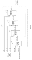
- a first fault detection system includes an inertial measurement unit (IMU) 2 that can form part of an inertial navigation system (INS).
- the IMU 2 contains a cluster of sensors such as accelerometers and gyros that sense linear acceleration (typically in three orthogonal directions) and rotation rates, respectively.
- the inertial measurements provided by the IMU 2 for a time t are combined to form an acceleration vector ⁇ ( t ) .
- Position measurements can be provided by any suitable position measurement equipment (PME) 4 such as a GPS receiver.
- Position measurements p ( t ) provided by the PME 4 for a time t can be in the form of spatial coordinates or absolute position on the earth for example.
- the PME might also provide velocity measurements (e.g. in the form of a Doppler velocity log (DVL)) in which case the fault detection system would be configured to compare these velocity measurements with unaided velocity measurements derived in a similar way to the unaided position measurements.
- VDL Doppler velocity log
- the IMU 2 and PME 4 form part of a dynamic position (DP) system for a marine vessel.
- DP dynamic position
- the buffers 6, 8 may be filled sequentially with acceleration vectors and position measurements during a preliminary or start-up process during which no fault detection would normally take place. Alternatively, the buffers may be preset to an arbitrary value (e.g. zero). Once the buffers 6, 8 are full then as subsequent acceleration vectors and position measurements are provided by the IMU 2 and PME 4 each second the oldest acceleration vectors and position measurements are simply discarded from the buffers.
- each buffer 6, 8 will therefore contain the most recent acceleration vectors and position measurements in the form of ⁇ ( t- ( N +1)), a( t-N ) ... ⁇ ( t -1) , ⁇ ( t ) and p ( t- ( N +1)), p ( t-N ) ...p ( t -1) , p ( t ) for a time t-(N +1) to time t .
- the fault detection method runs as a number of iterations. In this example an iteration takes place every second but it will be readily appreciated that other iteration rates can be used.
- the aided and unaided solution function blocks form part of a Kalman filter 16.
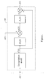
- Figure 2 shows the contents of the aided solution function block 10.
- the aided solution function block 10 derives an aided position estimate x'(t) (which is typically in the form of a vector) by combining together the previous aided position estimate x' ( t -1) with an acceleration vector ⁇ ( t ) provided by the IMU 2 and a position measurement p ( t ) provided by the PME 4.
- x'(t) which is typically in the form of a vector
- the acceleration vector that is used- will be the buffered acceleration vector ⁇ ( t- ( N +1)
- the position measurement that is used will be the buffered position measurement p ( t- ( N +1)).
- the first input to the aided solution function block 10 is the previous aided position estimate x' ( t -1).
- a mathematical model is used to extrapolate this vector forwards to time t producing an uncorrected, extrapolated, vector x *( t ).
- H 1 (t) is a mathematical model which extracts a prediction of accelerations and rotations of the marine vessel for comparison with the acceleration vector ⁇ ( t ) provided by the IMU 2.
- the error e 1 ( t ) between the predicted accelerations and rotations and the acceleration vector a ( t ) is multiplied by a gain matrix K 1 ,( t ) (typically referred to as the Kalman gain matrix) to produce a correction vector, which is added to the extrapolated vector x *( t ) to produce an unaided position estimate x(t).
- H 2 ( t ) is a mathematical model which extracts a prediction of the position of the marine vessel for comparison with the position measurement p ( t ) provided by the PME 4.
- the error e 2 ( t ) between the predicted position and the position measurement p ( t ) is multiplied by a gain matrix K 2 ( t ) to produce an additional correction vector, which is added to the unaided position estimate x(t) to produce an aided position estimate x' ( t ).
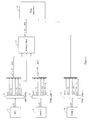
- Figure 3 shows the contents of the unaided solutions function block 12.
- the unaided solutions function block 12 derives a series of unaided position estimates x ( t-N ) ...x ( t -1) , x(t) (which are typically in the form of vector series) from the buffered acceleration vectors ⁇ ( t-N ) ...a ( t -1) , a( t ) and the previous unaided (or aided) position estimate. All of the series of unaided position estimates x ( t-N)...x ( t -1) , x(t) are derived for each iteration of the fault detection method.
- the unaided solutions function block 12 uses all of the buffered acceleration vectors for time t-N to time t during each iteration of the fault detection method and all of the processing to derive the series of unaided position estimates x ( t-N ) ...x ( t -1) , x(t) for an iteration at time t is completed before the next iteration at time t +1.
- the aided position estimate x '( t -4) that is derived from the aided solution function block 10 is used as a start condition to a first function block 18a.
- the aided position estimate x' ( t -4) is combined with a buffered acceleration vector ⁇ ( t -3) in the first function block 18a to derive a first unaided position estimate x(t-3).
- the first unaided position estimate x ( t -3) is combined with a buffered acceleration vector ⁇ ( t -2) in the second function block 18b to derive a first unaided position estimate x ( t -2) and so on to provide a series of unaided position estimates x ( t -3) ...x ( t -1) , x(t).
- each function block 18a to 18d derives an unaided position estimate x(t) by combining together the previous unaided position estimate x ( t -1) (or in the case of the first function block 18a, the previous aided position estimate x' ( t -1)) with an acceleration vector ⁇ ( t ) provided by the IMU 2.
- the acceleration vector that is used in function block 18a will be the buffered acceleration vector ⁇ ( t-N )
- the acceleration vector that is used in function block 18b will be the buffered acceleration vector ⁇ ( t- ( N -1)) and so on.
- the function block 18a will use as its start condition the aided position estimate x' ( t- ( N +1)) that is provided by the aided solution function block 10 and which in turn is derived for the same iteration of the fault detection method for a time t using the buffered acceleration vector ⁇ ( t- ( N +1)) and the buffered position measurement p ( t- ( N +1)) as described above.
- the first input to the function block 18a is the previous aided position estimate x '( t -1) and the first input to each subsequent function block 18b to 18d is the previous unaided position estimate x ( t -1) derived by the previous function block in the series.
- a mathematical model is used to extrapolate this vector forwards to time t producing an uncorrected, extrapolated, vector x* ( t ) .
- H 1 ( t ) is a mathematical model which extracts a prediction of accelerations and rotations of the marine vessel for comparison with the acceleration vector a ( t ) provided by the IMU 2.
- the error e 1 ( t ) between the predicted accelerations and rotations and the acceleration vector ⁇ ( t ) is multiplied by a gain matrix K 1 ( t ) to produce a correction vector, which is added to the extrapolated vector x *( t ) to produce an unaided position estimate x (t).
- The-fault detection method ⁇ may make use of all or part of the series of-unaided position estimates or just one of the unaided position estimates.
- An example of the detection of PME drift is shown in Figure 5 .
- the points marked with a x represent the error between the position measurements provided by the PME 4 and the corresponding unaided position estimates for a period of 60 seconds.
- only one unaided position estimate x(t) is used for each iteration of the fault detection method.
- the fault detection system will use the buffered acceleration data for the preceding 60 seconds (i.e.
- the second fault detection system is broadly similar to the first fault detection system but includes two separate PME located in parallel.
- Position measurements are provided by a first PME 4 and a second PME 20. Position measurements p 1 ( t ) are provided by the first PME 4 and stored in a first PME buffer 8 while position measurements p 2 ( t ) are provided by the second PME 20 and stored in a second PME buffer 22.
- the position measurements p 1 ( t ) provided by the first PME 4 are used as described above with an aided position estimate for an iteration at time t being derived from position measurement p 1 ( t- ( N +1)) in a first Kalman filter 16 and all or part of a series of position measurements p 1 ( t-N ) ...p 1 ( t-1 ) ,p 1 ( t ) being compared with all or part of a series of unaided position estimates x 1 (t- N ) ... x 1 ( t -1) , x 1 ( t ) in a first fault detection function block 14.
- the position measurements p 2 ( t ) provided by the second PME 20 are used in parallel with an aided position estimate for an iteration at time t being derived from position measurement p 2 ( t- ( N +1)) in a second Kalman filter 24 and all or part of a series of position measurements p 2 ( t-N ) ...p 2 ( t -1) , p 2 ( t ) being compared with all or part of a series of unaided position estimates x 2 ( t- N) ...x 2 ( t -1) , x 2 ( t ) in a second fault detection function block 26.
- Such a fault detection system derives separate aided and unaided position estimates for each PME in parallel using the same inertial measurements from the IMU 2 and is therefore capable of identifying faults independently in either PME.
- FIG. 6 shows two PME it will be readily appreciated that any number of PME can be connected together in parallel together with an associated PME buffer, Kalman filter and fault detection function block.
- the second fault detection system is broadly similar to the first fault detection system but includes two separate PME that both provide position measurements for the purpose of deriving the aided position estimates.
- the position measurements p 1 ( t ) provided by the first PME 4 are used as described above with an aided position estimate for an iteration at time t being derived from position measurement p 1 (t-(N+1)) in the Kalman filter 28 and compared with all or part of a series of unaided position estimates x ( t -N)... x ( t -1), x( t ) in the fault detection function block 14.
- the aided position estimate for the iteration at time t is also derived from position measurement p 2 ( t -( N +1)) provided by the second PME 20.
- p 2 ( t -1), p 2 ( t ) are buffered but are not used by the fault detection method. As a result, only a fault in the first PME 4 can be detected by the third fault detection system.
- the buffered position measurements p 2 ( t-N ) ...p 2 ( t -1) ,p 2 ( t ) may be used by the DP system, for example.
- the position measurements p 1 ( t ) and p 2 ( t ) provided by the first and second PME can be combined (e.g. to provide a weighted combination or average) which is then used to derive the error e 2 ( t ).
- a switch array can be used to select one or both of the position measurements p 1 ( t ) and p 2 ( t ) to derive the aided position estimate.
- Figure 7 shows two PME it will be readily appreciated that the position measurements from any number of PME can be used to derive each aided position estimate.
- a switch array (not shown) can be used to select one or more of the available position measurements to derive the aided position estimate in the Kalman filter 28. If two or more position measurements are selected then they can be combined (e.g. to provide a weighted combination or average) as described above.
- the fourth fault detection system is broadly similar to the third fault detection system but the position measurements provided by one PME are used for the purpose of deriving the aided position estimates while the position measurements provided by another PME are used for fault detection.
- the third fault detection system at least one PME provides position measurements that are used both for the purpose of deriving the aided position estimates and for fault detection, but in the fourth fault detection system the PME that is being checked for faults does not provide the position measurements that are used to derive the aided position estimates.
- the position measurements p 1 ( t ) provided by the first PME 4 are used as described above with an aided position estimate for an iteration at time t being derived from position measurement p 1 ( t- ( N +1)) in the Kalman filter 16. However, the position measurements p 1 ( t ) are not provided to the fault detection function block 14.
- the subsequent position measurements p 1 ( t-N ) ...p 1 ( t -1) , p 1 ( t ) are buffered but are not used by the fault detection method.
- the buffered position measurements p 1 ( t-N ) ...p 1 ( t -1) , p 1 ( t ) may be used by the DP system, for example.
- the position measurements p 2 ( t ) provided by the second PME 20 are stored in the PME buffer 22. All or part of the series of position measurement p 2 ( t-N)...p 2 ( t -1) , p 2 ( t ) are then supplied to the fault detection function block 14 and are compared with all or part of a series of unaided position estimates x ( t-N )... x ( t -1) , x(t) that is derived using the aided position estimate and the series of acceleration vectors ⁇ ( t-N ) ... ⁇ ( t -1) , ⁇ ( t ) provided by the IMU 2.
- the fourth fault detection system only a fault in the second PME 20 can be detected by the fourth fault detection system.
- the second, third and fourth fault detection systems can be used in combination with the position measurements from one or more PME being used to derive the aided position estimate but with the option to detect faults in one or more PME.
- one or more switch arrays can also be used to determine which position measurements are used to derive the aided position estimates and which of the buffered position measurements are provided to a fault detection function block to be used for fault detection purposes.
Landscapes
- Engineering & Computer Science (AREA)
- Radar, Positioning & Navigation (AREA)
- Remote Sensing (AREA)
- Physics & Mathematics (AREA)
- General Physics & Mathematics (AREA)
- Computer Networks & Wireless Communication (AREA)
- Theoretical Computer Science (AREA)
- Automation & Control Theory (AREA)
- Quality & Reliability (AREA)
- General Engineering & Computer Science (AREA)
- Navigation (AREA)
- Position Fixing By Use Of Radio Waves (AREA)
Priority Applications (7)
| Application Number | Priority Date | Filing Date | Title |
|---|---|---|---|
| EP09015817A EP2336721A1 (de) | 2009-12-21 | 2009-12-21 | Fehlererkennungsverfahren |
| BR112012015510A BR112012015510A2 (pt) | 2009-12-21 | 2010-12-16 | método de detecção de falhas |
| CN2010800585725A CN102792128A (zh) | 2009-12-21 | 2010-12-16 | 故障检测方法 |
| PCT/EP2010/007716 WO2011076365A1 (en) | 2009-12-21 | 2010-12-16 | Fault detection methods |
| EP10801133A EP2516963A1 (de) | 2009-12-21 | 2010-12-16 | Fehlerdetektionsverfahren |
| US13/514,200 US20130185020A1 (en) | 2009-12-21 | 2010-12-16 | Fault detection methods |
| RU2012122311/28A RU2012122311A (ru) | 2009-12-21 | 2010-12-16 | Способ и система для обнаружения неисправностей в оборудовании для определения местоположения |
Applications Claiming Priority (1)
| Application Number | Priority Date | Filing Date | Title |
|---|---|---|---|
| EP09015817A EP2336721A1 (de) | 2009-12-21 | 2009-12-21 | Fehlererkennungsverfahren |
Publications (1)
| Publication Number | Publication Date |
|---|---|
| EP2336721A1 true EP2336721A1 (de) | 2011-06-22 |
Family
ID=42122781
Family Applications (2)
| Application Number | Title | Priority Date | Filing Date |
|---|---|---|---|
| EP09015817A Withdrawn EP2336721A1 (de) | 2009-12-21 | 2009-12-21 | Fehlererkennungsverfahren |
| EP10801133A Withdrawn EP2516963A1 (de) | 2009-12-21 | 2010-12-16 | Fehlerdetektionsverfahren |
Family Applications After (1)
| Application Number | Title | Priority Date | Filing Date |
|---|---|---|---|
| EP10801133A Withdrawn EP2516963A1 (de) | 2009-12-21 | 2010-12-16 | Fehlerdetektionsverfahren |
Country Status (6)
| Country | Link |
|---|---|
| US (1) | US20130185020A1 (de) |
| EP (2) | EP2336721A1 (de) |
| CN (1) | CN102792128A (de) |
| BR (1) | BR112012015510A2 (de) |
| RU (1) | RU2012122311A (de) |
| WO (1) | WO2011076365A1 (de) |
Cited By (1)
| Publication number | Priority date | Publication date | Assignee | Title |
|---|---|---|---|---|
| CN102937449A (zh) * | 2012-10-19 | 2013-02-20 | 南京航空航天大学 | 惯性导航系统中跨音速段气压高度计和gps信息两步融合方法 |
Families Citing this family (8)
| Publication number | Priority date | Publication date | Assignee | Title |
|---|---|---|---|---|
| US9423250B1 (en) * | 2009-12-17 | 2016-08-23 | The Boeing Company | Position measurement correction using loop-closure and movement data |
| US9656593B2 (en) * | 2014-06-26 | 2017-05-23 | The Boeing Company | Flight vehicle autopilot |
| US10094668B2 (en) * | 2014-10-09 | 2018-10-09 | Honeywell International Inc. | Systems and methods for producing two independent dissimilar attitude solutions, two independent dissimilar inertial solutions or both from one improved navigation device |
| US10635111B2 (en) * | 2016-10-10 | 2020-04-28 | Rowan Companies, Inc. | Dynamic positioning of mobile offshore drilling unit |
| CN110555398B (zh) * | 2019-08-22 | 2021-11-30 | 杭州电子科技大学 | 一种基于滤波最优平滑确定故障首达时刻的故障诊断方法 |
| GB2592272B (en) * | 2020-02-24 | 2024-08-28 | Sonardyne Int Ltd | Vessel station maintenance control system and method of maintaining station for a vessel |
| CN112666422B (zh) * | 2020-11-25 | 2024-08-06 | 中国南方电网有限责任公司超高压输电公司 | 测量隐患定位方法 |
| CN112833919B (zh) * | 2021-03-25 | 2023-11-03 | 成都纵横自动化技术股份有限公司 | 一种多余度的惯性测量数据的管理方法及其系统 |
Citations (5)
| Publication number | Priority date | Publication date | Assignee | Title |
|---|---|---|---|---|
| US5527003A (en) * | 1994-07-27 | 1996-06-18 | Litton Systems, Inc. | Method for in-field updating of the gyro thermal calibration of an intertial navigation system |
| GB2323989A (en) * | 1997-04-02 | 1998-10-07 | Caterpillar Inc | Monitoring combined inertial/GPS system |
| US6311129B1 (en) * | 1998-04-06 | 2001-10-30 | American Gnc Corporation | Positioning process and system thereof |
| US6408245B1 (en) * | 2000-08-03 | 2002-06-18 | American Gnc Corporation | Filtering mechanization method of integrating global positioning system receiver with inertial measurement unit |
| US20090018772A1 (en) * | 2007-07-12 | 2009-01-15 | Takayuki Watanabe | Position Sensing Device And Method |
Family Cites Families (6)
| Publication number | Priority date | Publication date | Assignee | Title |
|---|---|---|---|---|
| US6516021B1 (en) * | 1999-09-14 | 2003-02-04 | The Aerospace Corporation | Global positioning systems and inertial measuring unit ultratight coupling method |
| US6664923B1 (en) * | 2002-09-24 | 2003-12-16 | Novatel, Inc. | Position and velocity Kalman filter for use with global navigation satelite system receivers |
| US20070032950A1 (en) * | 2005-08-05 | 2007-02-08 | Raven Industries, Inc. | Modular high-precision navigation system |
| US7579984B2 (en) * | 2005-11-23 | 2009-08-25 | The Boeing Company | Ultra-tightly coupled GPS and inertial navigation system for agile platforms |
| CN100462685C (zh) * | 2006-11-03 | 2009-02-18 | 北京航空航天大学 | 一种sins/gps组合导航系统的自适应加权反馈校正滤波方法 |
| JP2009058242A (ja) * | 2007-08-30 | 2009-03-19 | Alpine Electronics Inc | 車両位置・方位修正方法及び車両位置・方位修正装置 |
-
2009
- 2009-12-21 EP EP09015817A patent/EP2336721A1/de not_active Withdrawn
-
2010
- 2010-12-16 US US13/514,200 patent/US20130185020A1/en not_active Abandoned
- 2010-12-16 BR BR112012015510A patent/BR112012015510A2/pt not_active IP Right Cessation
- 2010-12-16 WO PCT/EP2010/007716 patent/WO2011076365A1/en not_active Ceased
- 2010-12-16 CN CN2010800585725A patent/CN102792128A/zh active Pending
- 2010-12-16 EP EP10801133A patent/EP2516963A1/de not_active Withdrawn
- 2010-12-16 RU RU2012122311/28A patent/RU2012122311A/ru not_active Application Discontinuation
Patent Citations (5)
| Publication number | Priority date | Publication date | Assignee | Title |
|---|---|---|---|---|
| US5527003A (en) * | 1994-07-27 | 1996-06-18 | Litton Systems, Inc. | Method for in-field updating of the gyro thermal calibration of an intertial navigation system |
| GB2323989A (en) * | 1997-04-02 | 1998-10-07 | Caterpillar Inc | Monitoring combined inertial/GPS system |
| US6311129B1 (en) * | 1998-04-06 | 2001-10-30 | American Gnc Corporation | Positioning process and system thereof |
| US6408245B1 (en) * | 2000-08-03 | 2002-06-18 | American Gnc Corporation | Filtering mechanization method of integrating global positioning system receiver with inertial measurement unit |
| US20090018772A1 (en) * | 2007-07-12 | 2009-01-15 | Takayuki Watanabe | Position Sensing Device And Method |
Non-Patent Citations (1)
| Title |
|---|
| STEPHENS, R.I; CRETOLLIER, F.; MORVAN, P.-Y.; CHAMBERLAIN, A.G.: "Integration of an inertial navigation system and DP", DYNAMIC POSITIONING CONFERENCE, 7 October 2008 (2008-10-07) |
Cited By (2)
| Publication number | Priority date | Publication date | Assignee | Title |
|---|---|---|---|---|
| CN102937449A (zh) * | 2012-10-19 | 2013-02-20 | 南京航空航天大学 | 惯性导航系统中跨音速段气压高度计和gps信息两步融合方法 |
| CN102937449B (zh) * | 2012-10-19 | 2015-01-14 | 南京航空航天大学 | 惯性导航系统中跨音速段气压高度计和gps信息两步融合方法 |
Also Published As
| Publication number | Publication date |
|---|---|
| EP2516963A1 (de) | 2012-10-31 |
| BR112012015510A2 (pt) | 2016-05-03 |
| WO2011076365A1 (en) | 2011-06-30 |
| CN102792128A (zh) | 2012-11-21 |
| RU2012122311A (ru) | 2014-02-10 |
| US20130185020A1 (en) | 2013-07-18 |
Similar Documents
| Publication | Publication Date | Title |
|---|---|---|
| EP2336721A1 (de) | Fehlererkennungsverfahren | |
| US8185309B2 (en) | Enhanced inertial system performance | |
| EP3006900B1 (de) | Systeme und verfahren zur lagefehlerdetektion auf grundlage von resten integrierter gnss- / intertialhybridfilter | |
| US9291714B2 (en) | Method and device for detecting and excluding multiple satellite failures in a GNSS system | |
| US8898013B2 (en) | Navigation device and process integrating several hybrid inertial navigation systems | |
| US5719764A (en) | Fault tolerant inertial reference system | |
| CN105698788B (zh) | 产生两个独立不同的姿态解、惯性解或两者的系统和方法 | |
| US7689357B2 (en) | Closed loop hybridising device with monitoring of the measurement integrity | |
| Bryne et al. | Design of inertial navigation systems for marine craft with adaptive wave filtering aided by triple‐redundant sensor packages | |
| US12228408B2 (en) | Sensor data fusion system with noise reduction and fault protection | |
| KR20230112709A (ko) | 관성 측정 유닛들에서의 오작동들을 검출하기 위한방법 | |
| US20210394790A1 (en) | Imu fault monitoring method and apparatus for multiple imus/gnss integrated navigation system | |
| CN106441287B (zh) | 用于活动安全应用的降阶失效保护imu系统 | |
| CN120274796A (zh) | Psi角修正模型下的冗余旋转惯导状态监测方法 | |
| KR101102856B1 (ko) | 우주비행체 구동기의 고장 검출기 및 고장 검출 방법 | |
| CN120800352B (zh) | 一种基于无人机的冗余组合导航方法及系统 | |
| Le Marchand et al. | Vehicle localization integrity based on trajectory monitoring | |
| EP4455610A2 (de) | Sicherheitskritische lagelösungen durch überwachung und überprüfung von winkelgeschwindigkeitssensoren | |
| JP4624192B2 (ja) | 測位データ処理方法 | |
| Bryne et al. | Inertial sensors for risk-based redundancy in dynamic positioning | |
| CN115930958B (zh) | 一种用于组合导航的gps失效容错处理方法 | |
| Pirmoradi et al. | An efficient algorithm for health monitoring and fault diagnosis in a spacecraft attitude determination system | |
| US10801861B2 (en) | Methods for aligning inertial navigation systems | |
| Oshman et al. | Robust, imm-based, tightly-coupled ins/gps in the presence of spoofing | |
| CN115931006B (zh) | 导航设备故障检测方法、装置及电子设备 |
Legal Events
| Date | Code | Title | Description |
|---|---|---|---|
| PUAI | Public reference made under article 153(3) epc to a published international application that has entered the european phase |
Free format text: ORIGINAL CODE: 0009012 |
|
| AK | Designated contracting states |
Kind code of ref document: A1 Designated state(s): AT BE BG CH CY CZ DE DK EE ES FI FR GB GR HR HU IE IS IT LI LT LU LV MC MK MT NL NO PL PT RO SE SI SK SM TR |
|
| AX | Request for extension of the european patent |
Extension state: AL BA RS |
|
| STAA | Information on the status of an ep patent application or granted ep patent |
Free format text: STATUS: THE APPLICATION IS DEEMED TO BE WITHDRAWN |
|
| 18D | Application deemed to be withdrawn |
Effective date: 20111223 |