EP2336731A1 - Detektion von Wasserverschwendung in einem Wasserverteilungssystem mit piezoelektrischem Gerät - Google Patents
Detektion von Wasserverschwendung in einem Wasserverteilungssystem mit piezoelektrischem Gerät Download PDFInfo
- Publication number
- EP2336731A1 EP2336731A1 EP09178994A EP09178994A EP2336731A1 EP 2336731 A1 EP2336731 A1 EP 2336731A1 EP 09178994 A EP09178994 A EP 09178994A EP 09178994 A EP09178994 A EP 09178994A EP 2336731 A1 EP2336731 A1 EP 2336731A1
- Authority
- EP
- European Patent Office
- Prior art keywords
- water
- signal
- timer
- flow
- tap
- Prior art date
- Legal status (The legal status is an assumption and is not a legal conclusion. Google has not performed a legal analysis and makes no representation as to the accuracy of the status listed.)
- Withdrawn
Links
- XLYOFNOQVPJJNP-UHFFFAOYSA-N water Substances O XLYOFNOQVPJJNP-UHFFFAOYSA-N 0.000 title claims abstract description 75
- 239000002699 waste material Substances 0.000 title claims description 7
- 238000001514 detection method Methods 0.000 title abstract description 3
- 238000000034 method Methods 0.000 claims description 7
- 230000004044 response Effects 0.000 claims description 3
- 239000012530 fluid Substances 0.000 description 9
- 239000000463 material Substances 0.000 description 7
- 238000005259 measurement Methods 0.000 description 7
- 230000003595 spectral effect Effects 0.000 description 7
- 230000010355 oscillation Effects 0.000 description 5
- 230000033001 locomotion Effects 0.000 description 4
- 239000002245 particle Substances 0.000 description 4
- 238000013461 design Methods 0.000 description 3
- 239000007789 gas Substances 0.000 description 3
- 239000007787 solid Substances 0.000 description 3
- 238000012546 transfer Methods 0.000 description 3
- 230000001680 brushing effect Effects 0.000 description 2
- 230000000694 effects Effects 0.000 description 2
- 239000012535 impurity Substances 0.000 description 2
- 239000007788 liquid Substances 0.000 description 2
- 238000012986 modification Methods 0.000 description 2
- 230000004048 modification Effects 0.000 description 2
- 230000003287 optical effect Effects 0.000 description 2
- 230000005236 sound signal Effects 0.000 description 2
- 238000001228 spectrum Methods 0.000 description 2
- 238000005406 washing Methods 0.000 description 2
- 229910001369 Brass Inorganic materials 0.000 description 1
- VYZAMTAEIAYCRO-UHFFFAOYSA-N Chromium Chemical compound [Cr] VYZAMTAEIAYCRO-UHFFFAOYSA-N 0.000 description 1
- 206010011878 Deafness Diseases 0.000 description 1
- 241001272720 Medialuna californiensis Species 0.000 description 1
- 230000003213 activating effect Effects 0.000 description 1
- 230000002411 adverse Effects 0.000 description 1
- 230000004075 alteration Effects 0.000 description 1
- 230000005540 biological transmission Effects 0.000 description 1
- 239000010951 brass Substances 0.000 description 1
- -1 but not limited to Substances 0.000 description 1
- 230000003247 decreasing effect Effects 0.000 description 1
- 230000001419 dependent effect Effects 0.000 description 1
- 230000001939 inductive effect Effects 0.000 description 1
- 230000002452 interceptive effect Effects 0.000 description 1
- 239000002184 metal Substances 0.000 description 1
- 238000012544 monitoring process Methods 0.000 description 1
- 230000000414 obstructive effect Effects 0.000 description 1
- 238000004321 preservation Methods 0.000 description 1
- 230000001105 regulatory effect Effects 0.000 description 1
- 230000000638 stimulation Effects 0.000 description 1
- 230000001960 triggered effect Effects 0.000 description 1
- 238000002379 ultrasonic velocimetry Methods 0.000 description 1
- 238000011144 upstream manufacturing Methods 0.000 description 1
- 238000010792 warming Methods 0.000 description 1
Images

Classifications
-
- G—PHYSICS
- G01—MEASURING; TESTING
- G01F—MEASURING VOLUME, VOLUME FLOW, MASS FLOW OR LIQUID LEVEL; METERING BY VOLUME
- G01F1/00—Measuring the volume flow or mass flow of fluid or fluent solid material wherein the fluid passes through a meter in a continuous flow
- G01F1/66—Measuring the volume flow or mass flow of fluid or fluent solid material wherein the fluid passes through a meter in a continuous flow by measuring frequency, phase shift or propagation time of electromagnetic or other waves, e.g. using ultrasonic flowmeters
- G01F1/666—Measuring the volume flow or mass flow of fluid or fluent solid material wherein the fluid passes through a meter in a continuous flow by measuring frequency, phase shift or propagation time of electromagnetic or other waves, e.g. using ultrasonic flowmeters by detecting noise and sounds generated by the flowing fluid
Definitions
- the present invention aims at reducing waste of water by increasing the awareness of water flow in water distribution systems in various areas such as domestic, office, institutional or recreational areas .
- Ultrasonic flow metres work with at least two different types of physical principles:
- the transit-time flowmetres measure the time of flight difference between an ultrasonic pulse sent in the flow direction and an ultrasonic pulse sent opposite the flow direction. Measurements can be adversely affected by impurities in the moving fluid such as for example gas and solid contents.
- Thet have two opposing transducers outside the pipe, one for measuring the time of a signal sent from a transducer upstream to a transducer downstream and the other for measuring the time in the opposite direction.
- Doppler metres use the frequency shift of an ultrasonic signal when it is reflected by impurities suspended in the moving fluid.
- the relative motions are determined by measuring the frequency shift between the ultrasonic frequency source, the receiver, and the fluid carrier. This method requires the presence of reflecting particles in the moving fluid and is therefore not suitable for clear liquids. It also requires that the fluid be transported in clear pipes.
- Acoustic flow sensors such as described in US-A-4,462,264 include a cylindrical wall defining a fluid-flow passage, a flow-metering rotor supported in the passage set in rotation by flowing fluid, an electric signal generator including piezoelectric transducer means cooperating with the rotor for producing an electric signal representative of the flow. Said method is complex and invasive.
- US-A-4,736,763 discloses a pipe flow detector for detecting unwanted fluid flow and for automatically triggering means for shutting off said unwanted flow.
- the detector comprises a piezoelectric film transducer attached to the pipe. Said transducer produces an electric signal in response to pipe vibration. The signal is then sent to a complex series of amplifiers and filters in order to identify a leak and then interrupt water flow.
- the present invention discloses an apparatus releasably affixed to a pipe or tap in a domestic water supply and designed to detect and quantify water flow in said water supply in order to inform the end user of water consumption and wherein said apparatus comprises a piezoelectric device.
- the present system is light, easy to place or remove and does not require any modification of the water distribution system. It can be placed on any pipe or tap and can be relocated to another position at any time, if and when desired.
- a pipe or tap is a mechanical system that presents some features typical of solid bodies, among which, the normal modes of oscillations. Any rigid body can be set in motion by an external solicitation even if its centre of mass velocity and all the angular velocities are null. This motion consists in oscillations that are typical of the specific body under consideration.
- the amplitude of the normal modes increases proportionally to the magnitude of external stimulation, whereas the frequencies depend on the material and geometry of the pipe or tap.
- the present inventors have observed that water flow through pipes or taps is capable of activating oscillations in the frequency range above a few KHz irrespective of material and geometry.
- the vibrations induced by the water flow are measured directly in the proximity of said tap.
- the present method is based on the measurement of high frequency vibration amplitude in the pipe or tap system in order to discriminate between the presence or absence of water flow.
- the root mean square amplitude (rms) of the vibration is used to monitor the energy transfer due to the water flow as represented in table I. TABLE 1.
- Tap condition Rms value (arbitrary units) Closed (no flow) 150 Open (small flow) 200 Open (moderate flow) 290 Widely open (large flow) 360
- the rms value of the vibration amplitude varies significantly and progressively with the flow intensity, regulated by the opening of the tap. It increases with increasing water flow
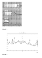
- the piezoelectric strips used in the present invention are parallelepiped pieces of piezoelectric material that develop a voltage difference across the material when it is subjected to a mechanical stress or strain. Examples of such devices are represented in Figure 1 .
- the sensor is part of a water saving device that is releasably affixed to a tap, or to a pipe, or to a hose,.or to a tube leading to a showerhead .
- the device can be effectively affixed to pipes, taps, hoses, and showerheads made from various materials including, but not limited to, metal, plastic, rubber or combinations thereof.
- the water saving device of the present invention comprises:
- the externally powered electronic amplifier is used to transform the low voltage electric signal, of the order of one mV, emitted by the piezoelectric device into a useable signal, of the order of at least one volt.
- the timer connected to the amplifier is triggered at the onset of water flow. It can be pre-set to a defined time limit T.
- the time interval T after which a signal is emitted can be set by the user at will or the device can be purchased with several pre-set options, depending upon its final use. It can be for example a short period of time for a. bathroom sink or a longer period of time for a showerhead hose .
- the signal generating device is connected to the timer and is designed to emit a signal an interval of time T, as determined by the timer, after the onset of water flow.
- the signal generating device can be selected from:
- the device can be set either to be silenced or to continue at a constant mode or to continue with an increasingly aggressive mode.
- the real aim of the water saving device is therefore awareness of water consumption.
- the device can thus be pre-fitted with any preset time interval of water flow for use in different situations or locations.
- the preset time intervals can be implemented either in a single device or in different 'single time' devices. Various situations such as brushing teeth, shower , hand washing or other can thus be accurately monitored using the appropriate preset time interval.
- the present invention also discloses a method for preparing a water saving device that comprises the steps of:
- the casing may be a smooth 'half moon' shaped clear transparent water coloured 'bubble' which will be hygienic while not interfering with chrome or brass feature design of fittings.
- the bubble may contain its component in a visible form or within a design or a logo.
- the 'bubble' may be embellished on the surface or below the skin with a feature such as for example a design or a logo or a colour.
- the fastening means may include velcro strips, snaps or magnets.
- the present invention also discloses a method for reducing waste of water in a water distribution system that comprises the steps of:
- the present invention further discloses the use of the present water saving device for warning about water consumption, for preserving the environment through water and energy saving and for reducing the home water bills.
- the present invention allows effective preservation of water resources and environment without the negative effect of decreasing the water pressure or shutting off water. It also allows maximum flexibility in determining how much and where water should be saved.
- Figure 2 represents the unfiltered power spectral densities of vibrations present in a common metallic tap in the absence of water flow. It presents a number of peaks that are typical of the normal modes of the solid body under consideration. The vibrations were measured directly on the pipe in the proximity of the tap.
- Figure 3 represents the unfiltered power spectral density of the same tap as that of Figure 2 during a moderate water flow.
- the peak structure was still present, such as for example the resonant peak at about 48 KHz, but a large energy 'bump' was observed in the spectrum between 20 and 40 KHz.
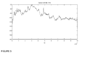
- Figures 4 and 5 represent respectively the filtered power spectral densities of the same tap as that of Figures 2 and 3 in the absence of water flow and during a moderate water flow. The data were filtered with a standard high pass filter set at 1 KHz.
Landscapes
- Physics & Mathematics (AREA)
- Electromagnetism (AREA)
- Fluid Mechanics (AREA)
- General Physics & Mathematics (AREA)
- Measuring Volume Flow (AREA)
- Domestic Plumbing Installations (AREA)
Priority Applications (8)
| Application Number | Priority Date | Filing Date | Title |
|---|---|---|---|
| EP09178994A EP2336731A1 (de) | 2009-12-13 | 2009-12-13 | Detektion von Wasserverschwendung in einem Wasserverteilungssystem mit piezoelektrischem Gerät |
| EP10796332A EP2510318A1 (de) | 2009-12-13 | 2010-12-11 | Wasserverschwendungsdetektor in einem wasserverteilungssystem mit einer piezoelektrischen vorrichtung |
| AU2010342810A AU2010342810B2 (en) | 2009-12-13 | 2010-12-11 | Water waste detection in water distribution system with piezoelectric device |
| JP2012542573A JP2013513742A (ja) | 2009-12-13 | 2010-12-11 | 配水システムにおける圧電装置を用いた水消費検出 |
| PCT/EP2010/069432 WO2011088933A1 (en) | 2009-12-13 | 2010-12-11 | Water waste detection in water distribution system with piezoelectric device |
| CN201080063705.8A CN102782461A (zh) | 2009-12-13 | 2010-12-11 | 使用压电装置的配水系统中的水浪费探测 |
| US13/515,421 US9127975B2 (en) | 2009-12-13 | 2010-12-11 | Apparatus and methods for water waste management in water distribution systems |
| CA2784084A CA2784084A1 (en) | 2009-12-13 | 2010-12-11 | Water waste detection in water distribution system with piezoelectric device |
Applications Claiming Priority (1)
| Application Number | Priority Date | Filing Date | Title |
|---|---|---|---|
| EP09178994A EP2336731A1 (de) | 2009-12-13 | 2009-12-13 | Detektion von Wasserverschwendung in einem Wasserverteilungssystem mit piezoelektrischem Gerät |
Publications (1)
| Publication Number | Publication Date |
|---|---|
| EP2336731A1 true EP2336731A1 (de) | 2011-06-22 |
Family
ID=42244735
Family Applications (2)
| Application Number | Title | Priority Date | Filing Date |
|---|---|---|---|
| EP09178994A Withdrawn EP2336731A1 (de) | 2009-12-13 | 2009-12-13 | Detektion von Wasserverschwendung in einem Wasserverteilungssystem mit piezoelektrischem Gerät |
| EP10796332A Withdrawn EP2510318A1 (de) | 2009-12-13 | 2010-12-11 | Wasserverschwendungsdetektor in einem wasserverteilungssystem mit einer piezoelektrischen vorrichtung |
Family Applications After (1)
| Application Number | Title | Priority Date | Filing Date |
|---|---|---|---|
| EP10796332A Withdrawn EP2510318A1 (de) | 2009-12-13 | 2010-12-11 | Wasserverschwendungsdetektor in einem wasserverteilungssystem mit einer piezoelektrischen vorrichtung |
Country Status (7)
| Country | Link |
|---|---|
| US (1) | US9127975B2 (de) |
| EP (2) | EP2336731A1 (de) |
| JP (1) | JP2013513742A (de) |
| CN (1) | CN102782461A (de) |
| AU (1) | AU2010342810B2 (de) |
| CA (1) | CA2784084A1 (de) |
| WO (1) | WO2011088933A1 (de) |
Cited By (1)
| Publication number | Priority date | Publication date | Assignee | Title |
|---|---|---|---|---|
| WO2015040607A1 (en) * | 2013-09-19 | 2015-03-26 | Dairymaster | A method and a device for determining the mass flow rate and the presence or absence of a liquid flowing in a pipe |
Families Citing this family (6)
| Publication number | Priority date | Publication date | Assignee | Title |
|---|---|---|---|---|
| JP6462243B2 (ja) * | 2014-06-24 | 2019-01-30 | 株式会社木村技研 | 看視システム |
| CN107764342A (zh) * | 2017-10-17 | 2018-03-06 | 安徽省锐凌计量器制造有限公司 | 一种利用液体压力检测流量的流量计 |
| JP6971332B2 (ja) * | 2018-01-23 | 2021-11-24 | 京セラ株式会社 | 流体測定装置、流体測定方法、及びプログラム |
| SE544526C2 (en) | 2020-12-07 | 2022-07-05 | Cleanguard Ab | A method, a computer program and a system for monitoring utilization of individual water appliances of a common water distribution system |
| SE2250292A1 (en) | 2022-03-04 | 2023-09-05 | Cleanguard Ab | A method, a computer program and a system for monitoring water consumption of water appliances of a common water distribution system |
| CN121466854B (zh) * | 2026-01-07 | 2026-04-28 | 合肥先微半导体材料有限公司 | 一种氟和氮混合气高精度混配方法 |
Citations (3)
| Publication number | Priority date | Publication date | Assignee | Title |
|---|---|---|---|---|
| US4736763A (en) * | 1987-02-26 | 1988-04-12 | Britton George L | Automatic device for the detection and shutoff of unwanted liquid flow in pipes |
| WO2005015135A2 (en) * | 2003-08-08 | 2005-02-17 | Cidra Corporation | Piezocable based sensor for measuring unsteady pressures inside a pipe |
| US20070001028A1 (en) * | 2005-05-27 | 2007-01-04 | Gysling Daniel L | Apparatus and method for measuring a parameter of a multiphase flow |
Family Cites Families (13)
| Publication number | Priority date | Publication date | Assignee | Title |
|---|---|---|---|---|
| US4462264A (en) | 1980-08-11 | 1984-07-31 | Wilgood Corporation | Acoustic flow sensors |
| JPS5783892A (en) * | 1980-11-12 | 1982-05-25 | Kogyo Gijutsuin | Infinitesimal vibration detecting alarm unit |
| JPS6361093U (de) * | 1986-10-07 | 1988-04-22 | ||
| US5243327A (en) * | 1992-03-25 | 1993-09-07 | K-Ii Enterprises Div. Of Wrtb, Inc. | Audible alarm for motion detection using dual mode transducer |
| JP3137011B2 (ja) * | 1996-12-06 | 2001-02-19 | 松下電器産業株式会社 | 感震装置 |
| RU2324171C2 (ru) * | 2003-07-18 | 2008-05-10 | Роузмаунт Инк. | Диагностика процесса |
| US7882750B2 (en) * | 2003-08-01 | 2011-02-08 | Cidra Corporate Services, Inc. | Method and apparatus for measuring parameters of a fluid flowing within a pipe using a configurable array of sensors |
| US7367239B2 (en) * | 2004-03-23 | 2008-05-06 | Cidra Corporation | Piezocable based sensor for measuring unsteady pressures inside a pipe |
| US7503227B2 (en) * | 2005-07-13 | 2009-03-17 | Cidra Corporate Services, Inc | Method and apparatus for measuring parameters of a fluid flow using an array of sensors |
| EP1977687A1 (de) * | 2007-04-05 | 2008-10-08 | Koninklijke Philips Electronics N.V. | Hydrogelbasierte Vorrichtung zur Erkennung eines Umweltzustands |
| US7969318B2 (en) * | 2007-06-15 | 2011-06-28 | Matt White | Flow detector with alarm features |
| JP2008175061A (ja) * | 2008-04-07 | 2008-07-31 | Toto Ltd | 自動水栓 |
| US8250924B2 (en) * | 2008-04-22 | 2012-08-28 | Rosemount Inc. | Industrial process device utilizing piezoelectric transducer |
-
2009
- 2009-12-13 EP EP09178994A patent/EP2336731A1/de not_active Withdrawn
-
2010
- 2010-12-11 WO PCT/EP2010/069432 patent/WO2011088933A1/en not_active Ceased
- 2010-12-11 EP EP10796332A patent/EP2510318A1/de not_active Withdrawn
- 2010-12-11 CN CN201080063705.8A patent/CN102782461A/zh active Pending
- 2010-12-11 US US13/515,421 patent/US9127975B2/en not_active Expired - Fee Related
- 2010-12-11 CA CA2784084A patent/CA2784084A1/en not_active Abandoned
- 2010-12-11 AU AU2010342810A patent/AU2010342810B2/en not_active Ceased
- 2010-12-11 JP JP2012542573A patent/JP2013513742A/ja active Pending
Patent Citations (3)
| Publication number | Priority date | Publication date | Assignee | Title |
|---|---|---|---|---|
| US4736763A (en) * | 1987-02-26 | 1988-04-12 | Britton George L | Automatic device for the detection and shutoff of unwanted liquid flow in pipes |
| WO2005015135A2 (en) * | 2003-08-08 | 2005-02-17 | Cidra Corporation | Piezocable based sensor for measuring unsteady pressures inside a pipe |
| US20070001028A1 (en) * | 2005-05-27 | 2007-01-04 | Gysling Daniel L | Apparatus and method for measuring a parameter of a multiphase flow |
Cited By (3)
| Publication number | Priority date | Publication date | Assignee | Title |
|---|---|---|---|---|
| WO2015040607A1 (en) * | 2013-09-19 | 2015-03-26 | Dairymaster | A method and a device for determining the mass flow rate and the presence or absence of a liquid flowing in a pipe |
| US10480975B2 (en) | 2013-09-19 | 2019-11-19 | Dairymaster | Method and a device for determining the mass flow rate and the presence or absence of a liquid flowing in a pipe |
| US11555724B2 (en) | 2013-09-19 | 2023-01-17 | Dairymaster | Method and a device for determining the mass flow rate and the presence or absence of a liquid flowing in a pipe |
Also Published As
| Publication number | Publication date |
|---|---|
| CA2784084A1 (en) | 2011-07-28 |
| EP2510318A1 (de) | 2012-10-17 |
| WO2011088933A1 (en) | 2011-07-28 |
| AU2010342810A1 (en) | 2012-07-05 |
| JP2013513742A (ja) | 2013-04-22 |
| US9127975B2 (en) | 2015-09-08 |
| US20120279315A1 (en) | 2012-11-08 |
| CN102782461A (zh) | 2012-11-14 |
| AU2010342810B2 (en) | 2014-07-10 |
Similar Documents
| Publication | Publication Date | Title |
|---|---|---|
| US9127975B2 (en) | Apparatus and methods for water waste management in water distribution systems | |
| US11566957B2 (en) | Pipe sensors | |
| AU2024219961B2 (en) | Location and flow rate meter | |
| EP3980728B1 (de) | Detektionsvorrichtung für eine flüssigkeitsleitung oder flüssigkeitsabgabevorrichtung | |
| WO2005010468A3 (en) | A configurable multi-function flow measurement apparatus having an array of sensors | |
| US4114557A (en) | Particle monitoring system | |
| JP2015215171A (ja) | 超音波流量計及び超音波吸収体の異常判定方法 | |
| DE60321131D1 (de) | Verfahren und einrichtung zur überwachung einer massenströmung in einer pneumatischen pipeline | |
| JP2012122740A (ja) | キャビテーション検出装置 | |
| AU5200399A (en) | Device for measuring the volume flow of a fluid in a pipe | |
| EP2390632A1 (de) | Durchflussmesser | |
| RU2008114990A (ru) | Способ и устройство акустического измерения расхода газа | |
| US5175530A (en) | Non-intrusive liquid flow detection apparatus | |
| JPH0344643B2 (de) | ||
| US3993017A (en) | Particle flow monitor | |
| JP2025521586A (ja) | 超音波キャビテーションセンサー | |
| JPH0337522A (ja) | 流速計 | |
| JP2632041B2 (ja) | 流速計 | |
| RU9955U1 (ru) | Вихреакустический преобразователь расхода | |
| KR102831498B1 (ko) | 진동 센서를 사용한 비-침습성 파이프라인 피그 신호 검출 | |
| JPH01138417A (ja) | ドップラー超音波流速測定装置 | |
| EA041151B1 (ru) | Неинтрузивный сигнализатор внутритрубного снаряда, использующий датчики вибрации | |
| ITAP20060002U1 (it) | Sensore di temperatura ad ultrasuoni per rilevamento incendi |
Legal Events
| Date | Code | Title | Description |
|---|---|---|---|
| PUAI | Public reference made under article 153(3) epc to a published international application that has entered the european phase |
Free format text: ORIGINAL CODE: 0009012 |
|
| AK | Designated contracting states |
Kind code of ref document: A1 Designated state(s): AT BE BG CH CY CZ DE DK EE ES FI FR GB GR HR HU IE IS IT LI LT LU LV MC MK MT NL NO PL PT RO SE SI SK SM TR |
|
| AX | Request for extension of the european patent |
Extension state: AL BA RS |
|
| STAA | Information on the status of an ep patent application or granted ep patent |
Free format text: STATUS: THE APPLICATION IS DEEMED TO BE WITHDRAWN |
|
| 18D | Application deemed to be withdrawn |
Effective date: 20111223 |