EP2336743A1 - Agencement d'étanchéification - Google Patents
Agencement d'étanchéification Download PDFInfo
- Publication number
- EP2336743A1 EP2336743A1 EP09015598A EP09015598A EP2336743A1 EP 2336743 A1 EP2336743 A1 EP 2336743A1 EP 09015598 A EP09015598 A EP 09015598A EP 09015598 A EP09015598 A EP 09015598A EP 2336743 A1 EP2336743 A1 EP 2336743A1
- Authority
- EP
- European Patent Office
- Prior art keywords
- sensor
- seal
- sealing arrangement
- arrangement according
- leakage
- Prior art date
- Legal status (The legal status is an assumption and is not a legal conclusion. Google has not performed a legal analysis and makes no representation as to the accuracy of the status listed.)
- Withdrawn
Links
- 238000007789 sealing Methods 0.000 claims abstract description 36
- 239000012528 membrane Substances 0.000 claims abstract description 26
- 238000011156 evaluation Methods 0.000 claims abstract description 11
- 239000000463 material Substances 0.000 claims abstract description 4
- 238000006073 displacement reaction Methods 0.000 claims description 18
- 239000013536 elastomeric material Substances 0.000 claims description 3
- 230000002093 peripheral effect Effects 0.000 claims description 3
- 229920001971 elastomer Polymers 0.000 abstract 1
- 239000000806 elastomer Substances 0.000 abstract 1
- 210000004379 membrane Anatomy 0.000 description 20
- 238000001514 detection method Methods 0.000 description 8
- 238000012544 monitoring process Methods 0.000 description 7
- 238000005259 measurement Methods 0.000 description 6
- 230000005540 biological transmission Effects 0.000 description 4
- 238000009434 installation Methods 0.000 description 3
- 230000002745 absorbent Effects 0.000 description 2
- 239000002250 absorbent Substances 0.000 description 2
- 230000001419 dependent effect Effects 0.000 description 2
- 239000012530 fluid Substances 0.000 description 2
- 239000007788 liquid Substances 0.000 description 2
- 239000010705 motor oil Substances 0.000 description 2
- 230000003287 optical effect Effects 0.000 description 2
- 229910000831 Steel Inorganic materials 0.000 description 1
- 230000000712 assembly Effects 0.000 description 1
- 238000000429 assembly Methods 0.000 description 1
- 238000010276 construction Methods 0.000 description 1
- 239000002826 coolant Substances 0.000 description 1
- 230000007423 decrease Effects 0.000 description 1
- 239000012208 gear oil Substances 0.000 description 1
- 239000000314 lubricant Substances 0.000 description 1
- 230000005405 multipole Effects 0.000 description 1
- 239000003921 oil Substances 0.000 description 1
- 229920006395 saturated elastomer Polymers 0.000 description 1
- 230000035945 sensitivity Effects 0.000 description 1
- 239000010959 steel Substances 0.000 description 1
- 239000000126 substance Substances 0.000 description 1
Images



Classifications
-
- G—PHYSICS
- G01—MEASURING; TESTING
- G01M—TESTING STATIC OR DYNAMIC BALANCE OF MACHINES OR STRUCTURES; TESTING OF STRUCTURES OR APPARATUS, NOT OTHERWISE PROVIDED FOR
- G01M3/00—Investigating fluid-tightness of structures
- G01M3/02—Investigating fluid-tightness of structures by using fluid or vacuum
- G01M3/26—Investigating fluid-tightness of structures by using fluid or vacuum by measuring rate of loss or gain of fluid, e.g. by pressure-responsive devices, by flow detectors
- G01M3/28—Investigating fluid-tightness of structures by using fluid or vacuum by measuring rate of loss or gain of fluid, e.g. by pressure-responsive devices, by flow detectors for pipes, cables or tubes; for pipe joints or seals; for valves ; for welds
- G01M3/2853—Investigating fluid-tightness of structures by using fluid or vacuum by measuring rate of loss or gain of fluid, e.g. by pressure-responsive devices, by flow detectors for pipes, cables or tubes; for pipe joints or seals; for valves ; for welds for pipe joints or seals
-
- F—MECHANICAL ENGINEERING; LIGHTING; HEATING; WEAPONS; BLASTING
- F16—ENGINEERING ELEMENTS AND UNITS; GENERAL MEASURES FOR PRODUCING AND MAINTAINING EFFECTIVE FUNCTIONING OF MACHINES OR INSTALLATIONS; THERMAL INSULATION IN GENERAL
- F16J—PISTONS; CYLINDERS; SEALINGS
- F16J15/00—Sealings
- F16J15/16—Sealings between relatively-moving surfaces
- F16J15/32—Sealings between relatively-moving surfaces with elastic sealings, e.g. O-rings
- F16J15/3296—Arrangements for monitoring the condition or operation of elastic sealings; Arrangements for control of elastic sealings, e.g. of their geometry or stiffness
Definitions
- the invention relates to a sealing arrangement comprising two machine elements and a seal which is sealingly arranged between the machine elements, wherein the seal defines two spaces to be sealed against each other, which are each filled at least partially with a medium to be sealed, wherein in the first space a relatively higher pressure prevails as in the second space and wherein on the side facing the second space of the seal, a module for detecting a leakage of the seal is arranged.
- Such a seal assembly with leakage detection is from the EP 1 916 509 A1 known.
- the first medium in the first space is sealed by a mechanical seal and the second medium in the second space by a radial shaft seal, wherein the mechanical seal and the radial shaft seal sealingly enclose a surface to be sealed of the first machine element.
- a module in the form of a further sealing ring is arranged axially between the mutually adjacent end faces of mechanical seal and radial shaft sealing ring, wherein a leak sensor and a leakage reservoir for detecting a leakage of the ring seal and / or the further sealing ring are provided.
- the leakage reservoir is formed by a nonwoven disc, which is arranged substantially concentric to the surface to be sealed of the first machine element.
- Leakage is absorbed by the leakage reservoir, detected by the leakage sensor and optically and / or acoustically indicated by the leakage sensor.
- An electronic signal is generated in an electronic evaluation unit. It should be noted, however, that the leakage reservoir formed by the nonwoven disc can only be used once. If the leakage reservoir is completely saturated, the entire sensor system must be replaced.
- the invention has for its object to develop a seal assembly of the known type such that can be dispensed to detect the leakage to an absorbent leakage depot and that a module used to detect a leak is used continuously, even if previously leakage through the Module has already been detected.
- the module comprises a throttle-like flow channel for the leakage and at least one sensor for detecting the leakage in the flow channel and that the sensor is signal-connected to an evaluation unit.
- a the service life The sealing arrangement limiting, absorbent leakage depot is not used. Occurring leakage is detected in contrast by the flow of leakage through the throttle-like flow channel.
- This flow channel does not serve as a leakage depot, but the controlled transport of the leakage and the establishment of a characteristic for the leakage quantity.
- Such a parameter for the leakage quantity may be the differential pressure within the flow channel between the flow inlet and the flow outlet. Flow velocity, direction and differential pressure thus define the strength of the leakage and allow conclusions about the degree of seal damage. Both flow velocity and flow direction can be evaluated, as will be explained in more detail later.
- the sealing arrangement according to the invention is suitable if in each case a fluid is disposed within the two spaces, for example in the first room with the relatively higher pressure engine oil and in the second room with the relatively lower pressure transmission oil.
- a fluid is disposed within the two spaces, for example in the first room with the relatively higher pressure engine oil and in the second room with the relatively lower pressure transmission oil.
- the first room there is an absolute pressure of about 2 to 5 bar
- in the second room an absolute pressure of about 1 bar.
- the detection of the leakage and its detection take place in the flow channel.
- the module has no signs of wear during a long service life, is maintenance-free and always reusable. The leakage is recorded consistently well over a long period of use.
- a leak-responsive response of the system can be adjusted, for example, via the geometry of the flow channel, as well as a leakage direction-dependent response of the monitoring system.
- the flow channel has the greatest possible length.
- the flow channel is formed meandering between a flow inlet and a flow outlet. Due to the meandering design, a long flow channel is achieved with externally compact dimensions. Deviating there is the possibility that the flow channel is formed, for example, spiral. Again, a long flow channel is achieved in externally compact dimensions.
- the senor is formed by a calorimetric flow sensor.
- Such non-contact measurement is virtually independent of the type of liquid leakage; the chemical properties of the leakage medium do not affect the detection of the leakage.
- the flow sensor comprises at least two temperature sensors spaced apart in the flow direction of the leakage.
- the temperature sensors are in each case in a good heat-conducting contact with the leakage, which flows through the flow channel, wherein the two temperature sensors are simultaneously well insulated against each other.
- Defined flow conditions through the flow channel are set significantly over the channel width. In the event of leakage, the leakage flows through the flow channel and thereby generates a characteristic temperature profile between the two temperature sensors.
- the location of the temperature sensors is, for example, near the flow outlet or near the flow inlet. Both positions are equally suitable for the detection of the leakage.
- the flow sensor comprises an electrically heatable hot wire, which is arranged in the flow direction between the temperature sensors.
- the hot wire creates a symmetrical temperature profile that is displaced in the event of leakage passing through the flow channel.
- the size of the displacement depends on the direction and the flow velocity of the leak.
- the operating principle is that of a calorimetric flow meter, for example for coolant and lubricant monitoring in the steel industry.
- the intensity of the leakage is a function of the temperature gradient between several temperature sensors.
- the first embodiment described above allows continuous monitoring of the leakage from the first space past the seal in the direction of the second space.
- a further improved measurement accuracy and thus improved knowledge about the degree of seal damage can be achieved in that the flow sensor comprises three spaced in the flow direction temperature sensors and that between the adjacent temperature sensors each have a hot wire is arranged.
- the change in the temperature difference between the temperature sensors is a measure of the flow velocity of the leakage.
- the aforementioned three temperature sensors are sufficient. This provides a good balance between benefit and effort.
- the use of a hot wire is advantageous to achieve a good resolution and thus a more accurate measurement result.
- the senor is designed as a pressure-actuable flap, wherein the flap can be brought into the open position when a pressure threshold value is exceeded in the flow channel.
- a pressure threshold value is exceeded in the flow channel.
- the mechanical flap is pressure-sensitive. If the pressure within the flow channel exceeds a critical pressure threshold value, the flap opens, thereby releasing a flow short circuit, wherein the opened flap is detected and displayed by the evaluation unit.
- the intensity of the leakage is a digital function of the differential pressure between the flow channel and the second space.
- the pressure threshold in the flow channel is not exceeded by the lack of leakage or only a slight leakage and the pressure-actuated flap remains in the closed position. This is an indication that the seal assembly is working properly.
- the senor may be formed as a differential pressure sensor.
- the differential pressure between the flow inlet and the flow outlet gives an indication of the intensity of the leakage.
- flow velocity and flow direction of the leak can be detected.
- the differential pressure is proportional to the flow velocity. The more leakage that flows, the greater the pressure build-up in the flow channel. The flow direction results from the sign of the differential pressure.
- the monitoring of the leakage by the differential pressure sensor is carried out continuously.
- the flap or the differential pressure sensor can each be arranged in the region of the flow outlet of the flow channel.
- the position of the flap can be arranged arbitrarily.
- the differential pressure sensor must measure between the flow inlet and the flow outlet.
- the senor may be formed as a differential pressure-controlled membrane with displacement sensor, wherein the membrane in the direction of the displacement sensor reciprocating and associated with the displacement sensor for detecting the path of the membrane adjacent.
- the membrane may consist of an elastically yielding material, for example of an elastomeric material. Such materials are available inexpensively in large numbers with different performance characteristics. The performance characteristics can be particularly easily adapted to the particular circumstances of the application.
- the differential pressure controlled membrane is preferably an integral part of the seal, wherein the movement / deflection of the membrane changes depending on the differential pressure between the two spaces.
- this leakage ensures a pressure relief in the first space and an increase in pressure in the second space, which is exposed to the comparatively low pressure.
- the membrane moves away from the displacement sensor in the direction of the first space. This changing distance is detected by the displacement sensor and transmitted to the evaluation unit.
- the intensity of the leakage is a function of the distance between the displacement sensor, the may be formed for example by an optical sensor, and the membrane. The leakage is monitored continuously.
- the seal may be formed as a radial shaft seal, wherein the membrane is arranged in the radial flange of the radial shaft seal.
- radial shaft seals in many dimensions are available at low cost.
- the membrane no additional space is required and also the installation effort does not differ from the assembly effort of radial shaft seals without differential pressure controlled membrane.
- the module can therefore form a preassemblable first unit with a multi-encoder based encoder and / or an associated magnetic field sensor.
- Encoder and / or magnetic field sensor can be arranged on the second space side facing the module. This side of the module facing the second space is the low pressure side.
- the magnetic field sensor can be assigned to the transmitter in the radial or axial direction.
- the installation space is limited in the axial direction in the above-mentioned sealing arrangements, wherein in the radial direction anyway dimensions are provided which must be sufficient for mounting the seal, in particular of the radial shaft seal.
- the transmitter is preferably enclosed by the magnetic field sensor on the outer peripheral side with a radial spacing.
- the encoder can be designed to detect the speed, direction of rotation, Absofutwinkel and / or torque.
- the module and the gasket may form a pre-assembled second unit.
- a summary of a preassembled units has proven to be advantageous, especially if not only the module with the encoder and / or the associated magnetic field sensor forms a preassemblable first unit but also if, in addition to said components, the seal is provided which completes the first unit to the pre-assembled second unit.
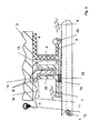
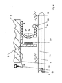
- FIGS. 1 to 5 Five embodiments of the claimed seal assembly are described below with reference to FIGS. 1 to 5 shown schematically and will be described in more detail below.
- the seal 3 is designed as a radial shaft sealing ring 26 and sealingly arranged between the two Maschinenelemnten 1, 2.
- the first machine element 1 is formed by a shaft, the second machine element 2 by a housing which encloses the first machine element 1 with a radial distance.
- the first space to be sealed 4 is located on the motor side of the seal 3, the second space to be sealed 5 transmission side of the seal 3, wherein the engine-side first space 4 with engine oil, the transmission side arranged second space 5 is filled with gear oil.
- the motor-side first space 4 is subjected to higher pressure than the transmission-side second space 5. For example, the pressure in the first space 4 3 bar, in the second space 5 1 bar.
- the module 8 for detecting a leakage 9 of the seal 3 is arranged on the second space 5 axially facing side of the seal 3.
- This module 8 comprises in the Fig. 1 to 3 and 5 in each case a throttle-shaped, meander-shaped flow channel 10, with a flow inlet 13 and a flow outlet 14. Deviating from this, the flow channel 10 may for example also be formed spirally.
- the leakage 9, which moves through the flow channel 10, is detected by the sensor 11, wherein this sensor 11 is signal-connected to an evaluation unit 12.
- the sensor 11 is formed by a calorimetric flow sensor 15. This comprises three in the flow direction 16 of the leakage 9 spaced-apart temperature sensors 17, 18, 20, wherein between the adjacent temperature sensors 17, 18, 20 each have a hot wire 19, 21 is arranged.
- the medium 6 to be sealed flows out of the first space 4 through the flow channel 10 and thereby generates a characteristic temperature profile between the individual temperature sensors 17, 18, 20.
- the sensitivity of the module 8 is increased in that between the temperature sensors 17, 18, 20, the hot wires 19, 21 are arranged.
- the evaluation is carried out by forming the temperature difference between adjacent temperature sensors 17, 18, 20, wherein the height of the temperature difference is proportional to the flow velocity of the leakage and the sign of the differential pressure is proportional to the flow direction of the leakage.
- a seal assembly is shown which differs from the seal assembly Fig. 1 distinguished by the design of the module 8.
- a pressure-actuated flap 22 is used in this exemplary embodiment, which can be brought into the open position when a pressure threshold value is exceeded in the flow channel 10. The position of the pressure-sensitive mechanical flap 22 is monitored.
- the intensity of the leakage 9 is a digital function of the differential pressure at the flap 22 between the pressure in the flow channel 10 and the pressure in the second space 5.
- the flow velocity and the flow direction are digitally detected by the pressure-actuable flap 22.
- the flap 22 When the flow velocity in the flow channel 10 is greater than the threshold, the flap 22 is open. If, on the other hand, the flow velocity in the flow channel 10 is smaller than the threshold value, the flap 22 is closed.
- Flow velocity and direction are detected in this embodiment by a sensor 11 designed as a differential pressure sensor.
- the intensity of the leakage is a function of the differential pressure between the flow inlet 13 and the flow outlet 14 of the meandering flow channel 10.
- the flow rate is proportional to the differential pressure. The more leakage 9 flows through the flow channel 10, the greater the pressure build-up in the flow channel 10.
- the flow direction of the leakage 9 can be detected on the basis of the sign of the differential pressure.
- Fig. 4 shows a fourth embodiment.
- a module 8 for detecting a leakage 9 of the seal 3 is provided, wherein the module 8 comprises a differential pressure controlled membrane 24 and a displacement sensor 25, which are associated with each other with an axial distance adjacent.
- the displacement sensor 25 is signal-conducting connected to the evaluation unit 12, just like the sensors 11 in the Fig. 1 to 3 ,
- the membrane 24 shown in FIG Embodiment consists of an elastomeric material, assumes the shape shown in dashed lines.
- the increasing axial Distance between the membrane 24 and the displacement sensor 25 is detected by the displacement sensor 25 and passed to the evaluation unit 12.
- the operator of the seal arrangement detects the intensity of the leakage. This is a function of the distance between displacement sensor 25, which may be formed, for example, as an optical sensor, and the membrane 24. The monitoring of the seal assembly is carried out continuously.
- Fig. 5 an embodiment is shown, which differs from the embodiments described above Fig. 1 to 4 differs in that in addition to a multipole encoder based encoder 28 and / or an associated magnetic field sensor 29 are used, which form a preassemblable first unit 30 with the module 8.
- the module 8 may be designed as well as modules 8 from the Fig. 1 to 4 ,
- Such a combination of module 8 and transmitter 28 and / or magnetic field sensor 29 to a preassemblable unit 30 is useful if in addition to the detection of the leakage speed, direction of rotation, absolute angle and / or torque of the seal assembly to be detected.
- a further simplified assembly can be achieved in that the first unit 30 is combined with the seal 3, the pre-assembled second unit 31st
- the encoder 28 is surrounded by the magnetic field sensor 29 at a radial distance on the outer peripheral side.
- the first unit 30 has compact dimensions in the axial direction; In general, however, there is also the possibility that the magnetic field sensor 29 is associated with the encoder 28 adjacent to the axial distance.
Landscapes
- Engineering & Computer Science (AREA)
- General Engineering & Computer Science (AREA)
- Physics & Mathematics (AREA)
- General Physics & Mathematics (AREA)
- Mechanical Engineering (AREA)
- Sealing Devices (AREA)
- Measuring Fluid Pressure (AREA)
Priority Applications (2)
| Application Number | Priority Date | Filing Date | Title |
|---|---|---|---|
| EP09015598A EP2336743A1 (fr) | 2009-12-17 | 2009-12-17 | Agencement d'étanchéification |
| EP11000802A EP2341328A1 (fr) | 2009-12-17 | 2009-12-17 | Agencement d'étanchéification |
Applications Claiming Priority (1)
| Application Number | Priority Date | Filing Date | Title |
|---|---|---|---|
| EP09015598A EP2336743A1 (fr) | 2009-12-17 | 2009-12-17 | Agencement d'étanchéification |
Related Child Applications (1)
| Application Number | Title | Priority Date | Filing Date |
|---|---|---|---|
| EP11000802.6 Division-Into | 2011-02-02 |
Publications (1)
| Publication Number | Publication Date |
|---|---|
| EP2336743A1 true EP2336743A1 (fr) | 2011-06-22 |
Family
ID=42102957
Family Applications (2)
| Application Number | Title | Priority Date | Filing Date |
|---|---|---|---|
| EP09015598A Withdrawn EP2336743A1 (fr) | 2009-12-17 | 2009-12-17 | Agencement d'étanchéification |
| EP11000802A Withdrawn EP2341328A1 (fr) | 2009-12-17 | 2009-12-17 | Agencement d'étanchéification |
Family Applications After (1)
| Application Number | Title | Priority Date | Filing Date |
|---|---|---|---|
| EP11000802A Withdrawn EP2341328A1 (fr) | 2009-12-17 | 2009-12-17 | Agencement d'étanchéification |
Country Status (1)
| Country | Link |
|---|---|
| EP (2) | EP2336743A1 (fr) |
Cited By (5)
| Publication number | Priority date | Publication date | Assignee | Title |
|---|---|---|---|---|
| WO2017137380A1 (fr) * | 2016-02-10 | 2017-08-17 | Güntner Gmbh & Co. Kg | Détecteur de glycol |
| CN107084246A (zh) * | 2017-05-31 | 2017-08-22 | 江苏海川卓越密封材料有限公司 | 一种双侧密封件 |
| EP3431781A1 (fr) * | 2017-07-21 | 2019-01-23 | Claverham Limited | Ensemble de piston |
| DE102017221510A1 (de) | 2017-11-30 | 2019-06-06 | Christian Maier GmbH & Co. KG | Verfahren zur Messung der Größe eines Leckagestromes einer Dichtung |
| CN111855084A (zh) * | 2019-12-27 | 2020-10-30 | 宁波旭升汽车技术股份有限公司 | 一种利用测漏装置检测变速箱阀体的气密性的方法 |
Families Citing this family (1)
| Publication number | Priority date | Publication date | Assignee | Title |
|---|---|---|---|---|
| CN106969865B (zh) * | 2017-02-22 | 2023-04-21 | 浙江万向精工有限公司 | 一种密封圈侧唇压力测量装置及测量方法 |
Citations (4)
| Publication number | Priority date | Publication date | Assignee | Title |
|---|---|---|---|---|
| JPS61159129A (ja) * | 1984-12-29 | 1986-07-18 | Sekitan Rotenbori Kikai Gijutsu Kenkyu Kumiai | 軸シ−ルの油漏洩検知装置 |
| US20030015840A1 (en) * | 2001-07-20 | 2003-01-23 | Davis Duane J. | Mechanical seal leak detector |
| DE10314923A1 (de) * | 2003-04-01 | 2004-11-18 | Carl Freudenberg Kg | Einrichtung zur Erfassung einer Leckage |
| EP1916509A1 (fr) | 2006-10-24 | 2008-04-30 | Carl Freudenberg KG | Arrangement d'étanchéité avec un dispositif de détection de fuites |
Family Cites Families (2)
| Publication number | Priority date | Publication date | Assignee | Title |
|---|---|---|---|---|
| DE4320939A1 (de) * | 1993-06-24 | 1995-01-05 | Freudenberg Carl Fa | Dichtung |
| US6817228B2 (en) * | 2002-04-01 | 2004-11-16 | Schlumberger Technology Corporation | Method and apparatus for detecting seal failure |
-
2009
- 2009-12-17 EP EP09015598A patent/EP2336743A1/fr not_active Withdrawn
- 2009-12-17 EP EP11000802A patent/EP2341328A1/fr not_active Withdrawn
Patent Citations (4)
| Publication number | Priority date | Publication date | Assignee | Title |
|---|---|---|---|---|
| JPS61159129A (ja) * | 1984-12-29 | 1986-07-18 | Sekitan Rotenbori Kikai Gijutsu Kenkyu Kumiai | 軸シ−ルの油漏洩検知装置 |
| US20030015840A1 (en) * | 2001-07-20 | 2003-01-23 | Davis Duane J. | Mechanical seal leak detector |
| DE10314923A1 (de) * | 2003-04-01 | 2004-11-18 | Carl Freudenberg Kg | Einrichtung zur Erfassung einer Leckage |
| EP1916509A1 (fr) | 2006-10-24 | 2008-04-30 | Carl Freudenberg KG | Arrangement d'étanchéité avec un dispositif de détection de fuites |
Cited By (9)
| Publication number | Priority date | Publication date | Assignee | Title |
|---|---|---|---|---|
| WO2017137380A1 (fr) * | 2016-02-10 | 2017-08-17 | Güntner Gmbh & Co. Kg | Détecteur de glycol |
| CN107084246A (zh) * | 2017-05-31 | 2017-08-22 | 江苏海川卓越密封材料有限公司 | 一种双侧密封件 |
| EP3431781A1 (fr) * | 2017-07-21 | 2019-01-23 | Claverham Limited | Ensemble de piston |
| DE102017221510A1 (de) | 2017-11-30 | 2019-06-06 | Christian Maier GmbH & Co. KG | Verfahren zur Messung der Größe eines Leckagestromes einer Dichtung |
| WO2019105854A1 (fr) | 2017-11-30 | 2019-06-06 | Christian Maier GmbH & Co. KG | Procédé de mesure de la grandeur d'un flux de fuite d'une garniture d'étanchéité |
| KR20200095512A (ko) * | 2017-11-30 | 2020-08-10 | 크리스티안 마이어 게엠베하 운트 코. 카게 | 밀봉부의 누출 흐름의 크기를 측정하는 방법 |
| JP2021504713A (ja) * | 2017-11-30 | 2021-02-15 | クリスティアン・マイヤー・ゲーエムベーハー・ウント・コ・カーゲー | シールの漏出流の量を測定する方法 |
| US12259299B2 (en) | 2017-11-30 | 2025-03-25 | Christian Maier GmbH & Co. KG | Method for measuring the size of a leak flow of a seal |
| CN111855084A (zh) * | 2019-12-27 | 2020-10-30 | 宁波旭升汽车技术股份有限公司 | 一种利用测漏装置检测变速箱阀体的气密性的方法 |
Also Published As
| Publication number | Publication date |
|---|---|
| EP2341328A1 (fr) | 2011-07-06 |
Similar Documents
| Publication | Publication Date | Title |
|---|---|---|
| EP2336743A1 (fr) | Agencement d'étanchéification | |
| DE60102520T2 (de) | Verfahren und Vorrichtung zum Warnen eines Bedieners eines Fahrzeugs | |
| DE102007045286B4 (de) | Verfahren zur Steuerung einer Filterwartungsanzeige | |
| DE4326343A1 (de) | Diganose-System für Regel- und Absperrarmaturen | |
| WO2018050803A1 (fr) | Compteur de fluide | |
| EP3450803A1 (fr) | Dispositif d'étanchéité et joint correspondant | |
| DE102010009194A1 (de) | Gleitringdichtung und Verfahren zur Optimierung von deren Betriebsverhalten | |
| EP1965107B1 (fr) | Bague d'étanchéité | |
| DE102020127285B3 (de) | Verfahren zur Feststellung von Leckagen einer Verdrängerpumpe | |
| EP3643942B1 (fr) | Dispositif de freinage | |
| EP3350446B1 (fr) | Dispositif pouvant être purgé servant à mesurer des processus d'écoulement de fluides | |
| DE102006060382A1 (de) | Vorrichtung zur Störungsfrüherkennung an Maschinen und/oder deren Bauteilen | |
| EP1916509B1 (fr) | Arrangement d'étanchéité avec un dispositif de détection de fuites | |
| EP2881584A1 (fr) | Détection de pannes sans capteur pour des pompes de dosage dotées d'un moteur pas à pas | |
| DE102017210270A1 (de) | Luftfilterelement mit integrierter Verunreinigungsmessung | |
| WO2012098136A1 (fr) | Convertisseur de mesure de pression | |
| WO2000025000A1 (fr) | Tete d'entrainement pour tringlerie entrainable en rotation, notamment pour entrainer une pompe a trous de mine | |
| DE102015005226B4 (de) | Rotor einer Fluidzentrifuge mit lndikatoreinrichtung | |
| DE202018100533U1 (de) | Baukastensystem für Durchflussmesseinrichtungen | |
| DE202023100442U1 (de) | Armatur zum Erfassen und Beeinflussen des Volumenstromes | |
| EP0182082B1 (fr) | Dispositif contrôleur de dosage | |
| DE102017221510A1 (de) | Verfahren zur Messung der Größe eines Leckagestromes einer Dichtung | |
| DE3439153C2 (de) | Kolben mit Dichtungsanordnung eines Strömungsgeschwindigkeits-Prüfgeräts | |
| AT410594B (de) | Vorrichtung zum messen der strömungsgeschwindigkeit und/oder -rate und dehnkörper zum messen des druckes eines fluiden mediums | |
| DE102019101632A1 (de) | Antriebsvorrichtung |
Legal Events
| Date | Code | Title | Description |
|---|---|---|---|
| PUAI | Public reference made under article 153(3) epc to a published international application that has entered the european phase |
Free format text: ORIGINAL CODE: 0009012 |
|
| AK | Designated contracting states |
Kind code of ref document: A1 Designated state(s): AT BE BG CH CY CZ DE DK EE ES FI FR GB GR HR HU IE IS IT LI LT LU LV MC MK MT NL NO PL PT RO SE SI SK SM TR |
|
| AX | Request for extension of the european patent |
Extension state: AL BA RS |
|
| 17P | Request for examination filed |
Effective date: 20110706 |
|
| GRAP | Despatch of communication of intention to grant a patent |
Free format text: ORIGINAL CODE: EPIDOSNIGR1 |
|
| INTG | Intention to grant announced |
Effective date: 20140123 |
|
| STAA | Information on the status of an ep patent application or granted ep patent |
Free format text: STATUS: THE APPLICATION IS DEEMED TO BE WITHDRAWN |
|
| 18D | Application deemed to be withdrawn |
Effective date: 20140603 |