EP2336749B1 - Optisches Detektionssystem für Kraftfahrzeuge mit mehreren Funktionen, einschließlich Detektion des Fahrbahnzustands - Google Patents
Optisches Detektionssystem für Kraftfahrzeuge mit mehreren Funktionen, einschließlich Detektion des Fahrbahnzustands Download PDFInfo
- Publication number
- EP2336749B1 EP2336749B1 EP09425520.5A EP09425520A EP2336749B1 EP 2336749 B1 EP2336749 B1 EP 2336749B1 EP 09425520 A EP09425520 A EP 09425520A EP 2336749 B1 EP2336749 B1 EP 2336749B1
- Authority
- EP
- European Patent Office
- Prior art keywords
- matrix
- road surface
- condition
- image
- filters
- Prior art date
- Legal status (The legal status is an assumption and is not a legal conclusion. Google has not performed a legal analysis and makes no representation as to the accuracy of the status listed.)
- Not-in-force
Links
- 238000001514 detection method Methods 0.000 title claims description 20
- 230000003287 optical effect Effects 0.000 title claims description 13
- 239000011159 matrix material Substances 0.000 claims description 35
- 230000003595 spectral effect Effects 0.000 claims description 13
- 230000005855 radiation Effects 0.000 claims description 12
- XLYOFNOQVPJJNP-UHFFFAOYSA-N water Substances O XLYOFNOQVPJJNP-UHFFFAOYSA-N 0.000 claims description 11
- 230000004297 night vision Effects 0.000 claims description 8
- 238000000034 method Methods 0.000 claims description 6
- 230000003449 preventive effect Effects 0.000 claims description 5
- 229910000530 Gallium indium arsenide Inorganic materials 0.000 claims description 3
- 230000005670 electromagnetic radiation Effects 0.000 claims description 3
- 230000000116 mitigating effect Effects 0.000 claims description 3
- 230000007613 environmental effect Effects 0.000 claims description 2
- 239000000463 material Substances 0.000 claims 1
- 238000011156 evaluation Methods 0.000 description 2
- 230000004438 eyesight Effects 0.000 description 2
- 238000007689 inspection Methods 0.000 description 2
- 238000002834 transmittance Methods 0.000 description 2
- 238000010521 absorption reaction Methods 0.000 description 1
- 238000004378 air conditioning Methods 0.000 description 1
- 230000004075 alteration Effects 0.000 description 1
- 239000011248 coating agent Substances 0.000 description 1
- 238000000576 coating method Methods 0.000 description 1
- 238000010586 diagram Methods 0.000 description 1
- 239000011521 glass Substances 0.000 description 1
- 229910052736 halogen Inorganic materials 0.000 description 1
- 150000002367 halogens Chemical class 0.000 description 1
- 238000012544 monitoring process Methods 0.000 description 1
- 230000035945 sensitivity Effects 0.000 description 1
- 238000000926 separation method Methods 0.000 description 1
- 238000010200 validation analysis Methods 0.000 description 1
Images


Classifications
-
- G—PHYSICS
- G01—MEASURING; TESTING
- G01N—INVESTIGATING OR ANALYSING MATERIALS BY DETERMINING THEIR CHEMICAL OR PHYSICAL PROPERTIES
- G01N21/00—Investigating or analysing materials by the use of optical means, i.e. using sub-millimetre waves, infrared, visible or ultraviolet light
- G01N21/17—Systems in which incident light is modified in accordance with the properties of the material investigated
- G01N21/55—Specular reflectivity
-
- G—PHYSICS
- G01—MEASURING; TESTING
- G01N—INVESTIGATING OR ANALYSING MATERIALS BY DETERMINING THEIR CHEMICAL OR PHYSICAL PROPERTIES
- G01N21/00—Investigating or analysing materials by the use of optical means, i.e. using sub-millimetre waves, infrared, visible or ultraviolet light
- G01N21/17—Systems in which incident light is modified in accordance with the properties of the material investigated
- G01N21/25—Colour; Spectral properties, i.e. comparison of effect of material on the light at two or more different wavelengths or wavelength bands
- G01N21/31—Investigating relative effect of material at wavelengths characteristic of specific elements or molecules, e.g. atomic absorption spectrometry
- G01N21/35—Investigating relative effect of material at wavelengths characteristic of specific elements or molecules, e.g. atomic absorption spectrometry using infrared light
- G01N21/359—Investigating relative effect of material at wavelengths characteristic of specific elements or molecules, e.g. atomic absorption spectrometry using infrared light using near infrared light
-
- G—PHYSICS
- G01—MEASURING; TESTING
- G01N—INVESTIGATING OR ANALYSING MATERIALS BY DETERMINING THEIR CHEMICAL OR PHYSICAL PROPERTIES
- G01N21/00—Investigating or analysing materials by the use of optical means, i.e. using sub-millimetre waves, infrared, visible or ultraviolet light
- G01N21/17—Systems in which incident light is modified in accordance with the properties of the material investigated
- G01N21/47—Scattering, i.e. diffuse reflection
- G01N21/4738—Diffuse reflection, e.g. also for testing fluids, fibrous materials
-
- G—PHYSICS
- G01—MEASURING; TESTING
- G01N—INVESTIGATING OR ANALYSING MATERIALS BY DETERMINING THEIR CHEMICAL OR PHYSICAL PROPERTIES
- G01N21/00—Investigating or analysing materials by the use of optical means, i.e. using sub-millimetre waves, infrared, visible or ultraviolet light
- G01N21/17—Systems in which incident light is modified in accordance with the properties of the material investigated
- G01N21/25—Colour; Spectral properties, i.e. comparison of effect of material on the light at two or more different wavelengths or wavelength bands
- G01N21/31—Investigating relative effect of material at wavelengths characteristic of specific elements or molecules, e.g. atomic absorption spectrometry
- G01N21/35—Investigating relative effect of material at wavelengths characteristic of specific elements or molecules, e.g. atomic absorption spectrometry using infrared light
- G01N21/3554—Investigating relative effect of material at wavelengths characteristic of specific elements or molecules, e.g. atomic absorption spectrometry using infrared light for determining moisture content
-
- G—PHYSICS
- G01—MEASURING; TESTING
- G01N—INVESTIGATING OR ANALYSING MATERIALS BY DETERMINING THEIR CHEMICAL OR PHYSICAL PROPERTIES
- G01N2201/00—Features of devices classified in G01N21/00
- G01N2201/02—Mechanical
- G01N2201/021—Special mounting in general
- G01N2201/0216—Vehicle borne
Definitions
- the present invention refers to optical detection systems for motor-vehicles, of the type able for detecting the condition of the road surface on which the vehicle is travelling in such a manner to distinguish, for example, between a dry, wet, snow-covered or ice-covered surface.
- the invention regards a system of this type comprising:
- a system as set forth in the preamble of claim 1 is known from EP 1 764 835 A1 .
- Document DE 197 47 917 A1 also discloses a system for the detection of water and ice using groups of four photodetectors two which have filters to receive only light in the absorbtion bands of water and ice respectively, the other two detectors receiving different wave lengths.
- the object of the present application is that of providing a system of the type specified above that is characterised by a high operational reliability and detection accuracy, the system in question being relatively simple and simultaneously suitable to also serve one or more further detection functions useful when driving the motor-vehicle.
- the invention is directed to a system having the features of claim 1 .
- control and processing electronic unit is programmed to control addressing of the pixels of the matrix ("windowing, window-of-interest readout" technique) of the camera to acquire at least three images: a first and a second image corresponding to the wavelengths wherein the radiation is respectively absorbed by water and ice, and at least a third image with full or partial spectral content in the band from the visible to the SWIR.
- the control and processing electronic unit is programmed to perform linear and interpolation operations through known methods (for example nearest neighbour, linear, cubic, and cubic spline) among the abovementioned images for each pixel of the matrix of the camera with the aim of detecting the condition of the road surface.
- the control and processing unit is programmed to calculate, for each pixel of the camera matrix, the ratios between the intensity of said first and said second image with respect to the intensity of said third image and for detecting - regarding each of said ratios - the condition of the road surface according to a reference map.
- the abovementioned control and processing electronic unit is programmed to use the abovementioned third image to meet one or more further preventive safety functions selected from among:
- An essential component of the optical detection system according to the present invention is represented by a camera 1 with InGaAs or Ge/Si matrix of pixels, which is for example positioned in the cabin of a motor-vehicle 2 (see figure 1 ) at position immediately at the back of the windshield, and supported for example by the rear-view mirror structure inside the motor-vehicle.
- FIG. 2 An exemplifying configuration of the optical detection system is illustrated in figure 2 indicated in which is an exploded view of the camera 1, where the reference number 3 indicates a multispectral objective, suitable to minimize the chromatic aberrations and maximize transmittance in the spectral band from the visible to the SWIR, and reference number 4 indicates a matrix of pixels composed of photodetectors based on InGaAs or Ge/Si, suitable to detect both radiations in the visible and near infrared (NIR), i.e. having a wavelength comprised between 380 and 900 nanometres, and radiations in the short wavelength infrared (SWIR), i.e. having a wavelength comprised between 900 and 1700 nanometres.
- NIR visible and near infrared
- SWIR short wavelength infrared
- Reference number 5 indicates a package for the vision sensor including the glass lid characterised in that it is provided with antireflection coating suitable to maximize transmittance in the spectral band from the visible to the SWIR, while reference number 6 indicates a matrix of optical filters obtained on the surface of the matrix of pixels 4 according to the known art and which shall be described in detail hereinafter.
- the camera 1 has an architecture known to those skilled in the art, which comprises a bias generator, time generator, column and line amplifiers, "shift registers", “gain”, “offset” and analogue/digital converter.
- This architecture transforms signals output from the photodetectors into a high dynamic digitized image (e.g. 120db) which is sent to a processing and control electronic unit indicated with reference number 8.
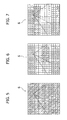
- the matrix of filters 6 comprises four-positions subgroups, wherein two positions are occupied by band-pass filters f 1 , f 2 with the typical spectral response curve indicated in figure 3 , with respective wavelengths centred on values at which the radiation is respectively absorbed by water and ice, and two positions c without filters in such a manner to allow complete passage of the band (see figure 4 ).
- the system according to the present invention does not employ an electromagnetic radiation emitter unit suitable to direct such radiation towards the road surface, exclusively dedicated to determine the condition of the road surface.
- halogen projectors - with which the motor-vehicle is equipped - are sufficient to light the portion of the road ahead of the vehicle.
- the optical detection system requires IRLED illuminators needed to serve other preventive safety functions such as, for example, the night vision (NV) function.
- NV night vision
- the aforedescribed configuration of the matrix of filters 6 is such that each filter transmits radiation to one and only one pixel of the matrix.
- the processing and control electronic unit 8 is programmed to control pixels of the matrix 4 of the camera to acquire at least three images: a first image and a second image corresponding to the wavelengths wherein the radiation is respectively absorbed by water and ice and at least a third image with full or partial spectral content in the band from the visible to the SWIR.
- the control unit 8 is programmed to perform linear and interpolation operations, through known techniques (for example nearest neighbor, linear, cubic, and cubic spline), of the abovementioned images for each pixel of the camera matrix and hence detect the condition of the road surface.
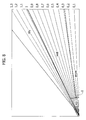
- control unit calculates, for each pixel of the matrix 4 of the camera 1, the ratios between the intensity of said first image and said second image with respect to the intensity of said third image and to detect the condition of the road surface for each of such ratios, according to a reference map which is illustrated in figure 8 .
- a reference map of this type as the criterion for evaluating the condition of the road surface was already proposed in the previous patent application of the Applicant indicated above, and still not open to public inspection as of date of filing of the present application.
- map is a cartesian plane wherein the values of the intensity of the abovementioned third image (i.e.
- the one with full or partial spectral content in the band from the visible to the SWIR are indicated on two abscissae, while the values of intensity of the first and second image are indicated on the axis of the ordinates.
- the corresponding light intensity values of the abovementioned three images may therefore be identified, hence allowing identifying the points of the reference map of figure 8 .
- the map is divided into areas corresponding to the various conditions of the road surface (dry, wet, ice, snow). As observable, the various areas are divided by straight lines converging in the origin of the axis, each line corresponding to a ratio between the light intensities indicated in the abscissa and in the ordinate.
- the system is capable of distinguishing between wet or snow condition and ice condition due to the fact that provided for is at least one separation line l (see figure 8 ) which is transverse with respect to the abovementioned lines converging in the origin of the axes and which separates the area corresponding to "ice" - which is closer to the origin of the axes - from the area corresponding to water and snow.
- FIG 7 Another alternative solution is illustrated in figure 7 , where the filters are prearranged only at one line, or only at some lines, of the matrix of photodetectors, that are dedicated to the detection of the condition of the road surface, full information regarding such condition being obtained in this case through the movement of the vehicle. It should be observed that also schematically represented in figures 5-7 is the road ahead of the vehicle.
- the specific characteristics of the optical detection system are such to allow application thereof also to meet other detection functions regarding preventive safety, in addition to those of detecting the condition of the road surface.
- the abovementioned third image - acquired by the camera with full or partial spectral content in the band from the visible to the SWIR - is used for such additional functions.
- the acquired image is processed to meet one or more further detection functions selected from among:
- the method for detecting the condition of the road surface consists of:
- the optical detection system is prearranged to provide data regarding the state of the condition of the road in correlation with the value of the environmental temperature sensor present on the vehicle ad use of the air conditioning function.
- the data may be compared - according to known decision strategies - by the processing and control electronic unit 8, in a control unit on board the vehicle or in a dedicated electronic unit.
- the optical detection system is prearranged to be optimised and used with the CAM and PCWI preventive safety functions.
- information provided regarding the condition of the road provided for by the abovementioned system allows optimising the algorithms used by the system for controlling and preparing braking depending on the grip conditions of the vehicle.
- the optical detection system is conceived to be used for the validation of or in correlation with grip evaluation obtained by the sensors provided for controlling and monitoring the lateral and longitudinal dynamic of the vehicle.
Landscapes
- Physics & Mathematics (AREA)
- Health & Medical Sciences (AREA)
- Life Sciences & Earth Sciences (AREA)
- Chemical & Material Sciences (AREA)
- Analytical Chemistry (AREA)
- Biochemistry (AREA)
- General Health & Medical Sciences (AREA)
- General Physics & Mathematics (AREA)
- Immunology (AREA)
- Pathology (AREA)
- Spectroscopy & Molecular Physics (AREA)
- Traffic Control Systems (AREA)
- Investigating Or Analysing Materials By Optical Means (AREA)
- Image Analysis (AREA)
- Length Measuring Devices By Optical Means (AREA)
Claims (9)
- Optisches Detektionssystem für Kraftfahrzeuge, das den Zustand der Fahrbahn, auf der sich das Fahrzeug bewegt, detektieren kann, wobei das System umfasst:- eine lichtempfindliche Sensoreinheit (1), die an Bord des Kraftfahrzeugs zum Empfang der durch die Fahrbahn zerstreuten, elektromagnetischen Strahlung eingebaut ist, und- eine elektronische Steuer- und Verarbeitungseinheit (8), die geeignet ist, um Signale zu empfangen, die von der lichtempfindlichen Sensoreinheit (1) ausgegeben werden, und um sie mit dem Ziel einer Erfassung des Zustands der Fahrbahn zu verarbeiten,
wobei die lichtempfindliche Sensoreinheit (1) eine Kamera mit einer Bildelementmatrix (4) ist, die aus lichtempfindlichen Sensoren basierend auf einem Material, vorzugsweise InGaAs oder Ge/Si, besteht, das geeignet ist, Strahlungen im sichtbaren und nahen Infrarot (NIR) zu detektieren, d. h., mit einer Wellenlänge, die zwischen 380 und 900 Nanometern enthalten ist, und
wobei die Kamera (1) eine Matrix von Filtern (6) umfasst, die vor mindestens einem Teil der Bildelementmatrix (4) angeordnet ist, derart, dass jedes Filter (f1, f2) die Strahlung zu einem einzigen Bildelement der Matrix (4) durchlässt,
wobei das System dadurch gekennzeichnet ist, dass:- die lichtempfindlichen Sensoren geeignet sind, Strahlungen auch im Infrarot kurzer Wellenlängen (SWIR) zu detektieren, d. h. mit einer Wellenlänge, die zwischen 900 und 1700 Nanometern enthalten ist, und- die Matrix von Filtern (6) Vierpositions-Untergruppen umfasst, wobei zwei Positionen von Bandfiltern (f1, f2) mit jeweiligen Wellenlängen eingenommen werden, die auf Werte konzentriert sind, bei denen die Strahlung jeweils durch Wasser und Eis absorbiert wird, und zwei Positionen (c) ohne Filter sind, derart, um einen vollständigen Durchlass des Spektralbandes zuzulassen;- die elektronische Steuer- und Verarbeitungseinheit (8) programmiert ist, um die Adressierung der Bildelemente der Matrix (4) der Kamera (1) für die Erfassung von mindestens drei Bildern zu steuern: einem ersten Bild und einem zweiten Bild, das den Wellenlängen entspricht, bei denen die Strahlung jeweils durch Wasser und Eis absorbiert wird, und mindestens einem dritten Bild mit vollem oder teilweisem Spektralgehalt in dem Band vom sichtbaren Infrarot zum SWIR;- die elektronische Steuer- und Verarbeitungseinheit (8) programmiert ist, um die oben erwähnten Bilder für jedes Bildelement der Matrix (4) der Kamera (1) zu verarbeiten und folglich den Fahrbahnzustand zu detektieren;- die elektronische Steuer- und Verarbeitungseinheit (8) programmiert ist, um für jedes Bildelement der Kameramatrix die Verhältnisse zwischen der Intensität des ersten Bildes und des zweiten Bildes hinsichtlich der Intensität des dritten Bildes zu berechnen und den Fahrbahnzustand entsprechend einer Bezugsbildvorlage zu detektieren; und- die Bezugsbildvorlage eine rechtwinklige Ebene ist, wobei die Intensitätswerte des dritten Bildes auf einer ersten rechtwinkligen Achse angezeigt werden, die Intensitätswerte des ersten Bildes und des zweiten Bildes auf einer zweiten rechtwinkligen Achse angezeigt werden, und wobei diese rechtwinklige Ebene in Unterbereiche geteilt ist, die von vornherein als den unterschiedlichen Fahrbahnzuständen entsprechend erkannt werden. - System nach Anspruch 1, dadurch gekennzeichnet, dass die Grenzlinien in der Bezugsbildvorlage, die solche Unterbereiche voneinander teilen, sowohl Linienabschnitte umfassen, die radial zum Koordinatenursprung der rechtwinkligen Achsen hin konvergieren, als auch Linienabschnitte, die bezüglich der radialen Linienabschnitte quer gerichtet sind, wobei einer der quer gerichteten Linienabschnitte einen dem Vorhandensein von Eis auf der Fahrbahn entsprechenden Bereich der Bildvorlage von Bereichen trennt, die dem Vorhandensein von Wasser oder Schnee auf der Fahrbahn entsprechen.
- System nach Anspruch 1, dadurch gekennzeichnet, dass die elektronische Steuer- und Verarbeitungseinheit (8) zur Nutzung des dritten Bildes programmiert ist, derart, um einer oder mehreren weiteren vorbeugenden Sicherheitsfunktionen gerecht zu werden, die ausgewählt sind aus:- Fahrbahnabweichungswarnung oder LDW,- Fernlichteinstellung (HBA),- Verkehrssignalerkennung (TSR),- Nachtsicht (NV),- Kollisionsvermeidung und -abschwächung (CAM), und- Warnung vor dem Aufprall und Eingriff (PCWI).
- System nach Anspruch 1, dadurch gekennzeichnet, dass die Matrix von Filtern (6) vor der gesamten Ausdehnung der Matrix von lichtempfindlichen Sensoren (4) angeordnet ist.
- System nach Anspruch 1, dadurch gekennzeichnet, dass die Matrix von Filtern nur vor einem Abschnitt der Matrix von lichtempfindlichen Sensoren (4) angeordnet ist, der zur Erfassung des Fahrbahnzustands vorgesehen ist.
- System nach Anspruch 1, dadurch gekennzeichnet, dass die Matrix von Filtern (6) nur vor einer Linie oder einigen Linien der Matrix lichtempfindlicher Sensoren (4) angeordnet ist, die zur Erfassung des Fahrbahnzustands vorgesehen sind, wobei vollständige Informationen, die den Fahrbahnzustand betreffen, erhalten werden, wenn sich das Fahrzeug bewegt.
- System nach Anspruch 3, dadurch gekennzeichnet, dass die elektronische Steuer- und Verarbeitungseinheit (8) programmiert ist, um den Algorithmen der CAM- und PCWI-Funktionen Informationen bereitzustellen, die den Fahrbahnzustand betreffen.
- System nach Anspruch 3, dadurch gekennzeichnet, dass die elektronische Steuer- und Verarbeitungseinheit (8) programmiert ist, um Einrichtungen zum Abschätzen der Griffigkeit des Fahrzeugs gegenüber der Straße in Systemen zur Steuerung der Dynamik des Fahrzeugs in Längs- und Querrichtung Informationen bereitzustellen, die den Zustand der Straße betreffen.
- System nach Anspruch 1, dadurch gekennzeichnet, dass die elektronische Steuer- und Verarbeitungseinheit (8) programmiert ist, um Informationen, die den Zustand der Straße betreffen, in Korrelation mit dem Wert eines Umgebungstemperatursensors bereitzustellen.
Priority Applications (3)
| Application Number | Priority Date | Filing Date | Title |
|---|---|---|---|
| EP12190845.3A EP2557414B1 (de) | 2009-12-21 | 2009-12-21 | Optisches Detektionssystem für Kraftfahrzeuge mit mehreren Funktionen, einschließlich Detektion des Fahrbahnzustands |
| EP09425520.5A EP2336749B1 (de) | 2009-12-21 | 2009-12-21 | Optisches Detektionssystem für Kraftfahrzeuge mit mehreren Funktionen, einschließlich Detektion des Fahrbahnzustands |
| US12/891,083 US8477192B2 (en) | 2009-12-21 | 2010-09-27 | Optical detection system for motor-vehicles having multiple functions, including detection of the condition of the road surface |
Applications Claiming Priority (1)
| Application Number | Priority Date | Filing Date | Title |
|---|---|---|---|
| EP09425520.5A EP2336749B1 (de) | 2009-12-21 | 2009-12-21 | Optisches Detektionssystem für Kraftfahrzeuge mit mehreren Funktionen, einschließlich Detektion des Fahrbahnzustands |
Related Child Applications (2)
| Application Number | Title | Priority Date | Filing Date |
|---|---|---|---|
| EP12190845.3A Division EP2557414B1 (de) | 2009-12-21 | 2009-12-21 | Optisches Detektionssystem für Kraftfahrzeuge mit mehreren Funktionen, einschließlich Detektion des Fahrbahnzustands |
| EP12190845.3A Division-Into EP2557414B1 (de) | 2009-12-21 | 2009-12-21 | Optisches Detektionssystem für Kraftfahrzeuge mit mehreren Funktionen, einschließlich Detektion des Fahrbahnzustands |
Publications (2)
| Publication Number | Publication Date |
|---|---|
| EP2336749A1 EP2336749A1 (de) | 2011-06-22 |
| EP2336749B1 true EP2336749B1 (de) | 2015-09-02 |
Family
ID=42102241
Family Applications (2)
| Application Number | Title | Priority Date | Filing Date |
|---|---|---|---|
| EP12190845.3A Not-in-force EP2557414B1 (de) | 2009-12-21 | 2009-12-21 | Optisches Detektionssystem für Kraftfahrzeuge mit mehreren Funktionen, einschließlich Detektion des Fahrbahnzustands |
| EP09425520.5A Not-in-force EP2336749B1 (de) | 2009-12-21 | 2009-12-21 | Optisches Detektionssystem für Kraftfahrzeuge mit mehreren Funktionen, einschließlich Detektion des Fahrbahnzustands |
Family Applications Before (1)
| Application Number | Title | Priority Date | Filing Date |
|---|---|---|---|
| EP12190845.3A Not-in-force EP2557414B1 (de) | 2009-12-21 | 2009-12-21 | Optisches Detektionssystem für Kraftfahrzeuge mit mehreren Funktionen, einschließlich Detektion des Fahrbahnzustands |
Country Status (2)
| Country | Link |
|---|---|
| US (1) | US8477192B2 (de) |
| EP (2) | EP2557414B1 (de) |
Families Citing this family (23)
| Publication number | Priority date | Publication date | Assignee | Title |
|---|---|---|---|---|
| ES2833102T3 (es) * | 2010-02-23 | 2021-06-14 | Lg Electronics Inc | Refrigerador |
| DE102011081391A1 (de) * | 2011-08-23 | 2013-02-28 | Robert Bosch Gmbh | Verfahren und Vorrichtung zum Erkennen von Störobjekten in der Umgebungsluft eines Fahrzeugs |
| KR101349025B1 (ko) * | 2011-11-25 | 2014-01-10 | 현대자동차주식회사 | 원적외선 스마트 나이트 뷰를 위한 차선 정보 합성 장치 및 방법 |
| US9007438B2 (en) * | 2012-05-21 | 2015-04-14 | Xerox Corporation | 3D imaging using structured light for accurate vehicle occupancy detection |
| DE102013002333A1 (de) * | 2013-02-12 | 2014-08-14 | Continental Teves Ag & Co. Ohg | Verfahren und Strahlensensormodul zur vorausschauenden Straßenzustandsbestimmung in einem Fahrzeug |
| US9299007B2 (en) * | 2014-01-28 | 2016-03-29 | Ncr Corporation | Methods and apparatus for item identification using brightness compensation |
| DE102014208625A1 (de) | 2014-05-08 | 2015-11-12 | Continental Teves Ag & Co. Ohg | Verfahren zur Regelung der Fahrdynamik eines Kraftfahrzeugs |
| DE102015205233A1 (de) * | 2015-03-23 | 2016-09-29 | Conti Temic Microelectronic Gmbh | Sensorvorrichtung und herstellungsverfahren |
| US20170096144A1 (en) * | 2015-10-05 | 2017-04-06 | Ford Global Technologies, Llc | System and Method for Inspecting Road Surfaces |
| JP6361631B2 (ja) * | 2015-10-29 | 2018-07-25 | Smk株式会社 | 車載センサ、車両用灯具及び車両 |
| US20170293814A1 (en) * | 2016-04-07 | 2017-10-12 | Ford Global Technologies, Llc | System and Method for Inspecting Road Surfaces |
| DE102018100805A1 (de) * | 2018-01-16 | 2019-07-18 | Connaught Electronics Ltd. | Reinigungsvorrichtung zum Reinigen eines lichtdurchlässigen Frontelements eines optischen Sensors für ein Kraftfahrzeug, Anordnung sowie Verfahren |
| DE102018108809B4 (de) * | 2018-04-13 | 2020-02-06 | Hensoldt Optronics Gmbh | Kamerasystem |
| FR3085923B1 (fr) * | 2018-09-19 | 2021-04-02 | Valeo Systemes Dessuyage | Dispositif de detection de neige sur une surface vitree d'un vehicule automobile |
| EP3874316B1 (de) * | 2018-10-31 | 2025-12-17 | The Regents Of The University Of Michigan | Optimale spektralbänder für aktive sichtsysteme |
| US11021159B2 (en) | 2019-07-10 | 2021-06-01 | Ford Global Technologies, Llc | Road surface condition detection |
| GB2587628B (en) * | 2019-10-01 | 2021-10-27 | Tracsense As | Surface condition sensor |
| DE102020203293B4 (de) | 2020-03-13 | 2022-09-08 | Fraunhofer-Gesellschaft zur Förderung der angewandten Forschung eingetragener Verein | Eine Vorrichtung zum Erkennen von Wasser auf einer Oberfläche und ein Verfahren zum Erkennen von Wasser auf einer Oberfläche |
| EP4148683A1 (de) | 2021-09-10 | 2023-03-15 | Fraunhofer-Gesellschaft zur Förderung der angewandten Forschung e.V. | Eine vorrichtung und ein verfahren zum erkennen eines zustands einer fahrbahnoberfläche |
| DE102022201523A1 (de) | 2021-09-10 | 2023-03-16 | Fraunhofer-Gesellschaft zur Förderung der angewandten Forschung eingetragener Verein | Ein Bildsensor, ein Verfahren zum Betreiben eines Bildsensors, ein Verfahren zum Herstellen eines Bildsensors und ein stationäres Gerät oder ein Fahrzeug oder eine Drohne mit einem Bildsensor |
| JP7854304B2 (ja) * | 2022-02-09 | 2026-05-01 | 株式会社小糸製作所 | 測定装置 |
| JP2023127897A (ja) * | 2022-03-02 | 2023-09-14 | 株式会社ミツバ | 情報処理装置、情報処理システム、情報処理方法、及びプログラム |
| CN115165033B (zh) * | 2022-07-06 | 2024-06-14 | 中国民航大学 | 一种机场跑道路面高厚度积水测量装置及方法 |
Family Cites Families (10)
| Publication number | Priority date | Publication date | Assignee | Title |
|---|---|---|---|---|
| DE3023444C2 (de) * | 1979-06-29 | 1985-07-11 | Omron Tateisi Electronics Co., Kyoto | Einrichtung zur Ermittlung des witterungsbedingten Straßenzustandes |
| DE4008280A1 (de) * | 1990-03-15 | 1991-09-19 | Tzn Forschung & Entwicklung | Verfahren zur ermittlung des fahrbahnoberflaechenzustandes |
| DE19506550A1 (de) * | 1995-02-24 | 1996-08-29 | Inst Chemo Biosensorik | Verfahren zur verzugsfreien Feststellung von und zur Warnung vor durch Glättebildung bedingte Gefahren und Vorrichtung zur Durchführung des Verfahrens |
| DE19747017A1 (de) * | 1997-10-24 | 1999-04-29 | Itt Mfg Enterprises Inc | Detektion von Wasser- und/oder Eisschichten auf der Straße unter Verwendung einer Lichtquelle |
| DE19747917A1 (de) | 1997-10-30 | 1999-05-06 | Abr Handel Gmbh | Verfahren zur Aufarbeitung von metallisch belasteter Salzsäure |
| ITTO20020950A1 (it) * | 2002-11-05 | 2004-05-06 | Fiat Ricerche | Sistema di visione integrato multifunzionale, con matrice |
| EP1635163B1 (de) * | 2004-09-09 | 2017-05-31 | Volkswagen Aktiengesellschaft | Kraftfahrzeug mit einer Vorrichtung zur Bestimmung der Beschaffenheit einer Oberfläche einer Fahrbahn |
| DE602005004544T2 (de) | 2005-09-19 | 2008-04-30 | CRF Società Consortile per Azioni, Orbassano | Multifunktioneller optischer Sensor mit einer an Mikrolinsen gekoppelten Matrix von Photodetektoren |
| EP1976296A4 (de) * | 2006-01-20 | 2011-11-16 | Sumitomo Electric Industries | Infrarot-abbildungssystem |
| FR2946157B1 (fr) * | 2009-06-02 | 2015-03-27 | Commissariat Energie Atomique | Systeme d'imagerie a microlentilles et dispositif associe pour la detection d'un echantillon. |
-
2009
- 2009-12-21 EP EP12190845.3A patent/EP2557414B1/de not_active Not-in-force
- 2009-12-21 EP EP09425520.5A patent/EP2336749B1/de not_active Not-in-force
-
2010
- 2010-09-27 US US12/891,083 patent/US8477192B2/en not_active Expired - Fee Related
Also Published As
| Publication number | Publication date |
|---|---|
| EP2557414A3 (de) | 2013-04-03 |
| EP2557414A2 (de) | 2013-02-13 |
| EP2557414B1 (de) | 2015-03-25 |
| US20110149076A1 (en) | 2011-06-23 |
| US8477192B2 (en) | 2013-07-02 |
| EP2336749A1 (de) | 2011-06-22 |
Similar Documents
| Publication | Publication Date | Title |
|---|---|---|
| EP2336749B1 (de) | Optisches Detektionssystem für Kraftfahrzeuge mit mehreren Funktionen, einschließlich Detektion des Fahrbahnzustands | |
| US6049387A (en) | Process for determining the condition of a road surface and system for implementing the process | |
| CN104512411B (zh) | 车辆控制系统及图像传感器 | |
| US10137842B2 (en) | Camera system for a vehicle | |
| US9335264B2 (en) | Detection of raindrops on a pane by means of a camera and lighting | |
| JP4103179B2 (ja) | 環境認識装置 | |
| CN102782478B (zh) | 用于借助光谱学进行雾识别的方法和装置 | |
| JP5995140B2 (ja) | 撮像装置及びこれを備えた車両システム並びに画像処理方法 | |
| US20120026318A1 (en) | Camera system for detecting a state of a vehicle window pane | |
| US9676329B2 (en) | Camera system and method for operating a camera system for a motor vehicle | |
| JP5936098B2 (ja) | 撮像装置及びこれを備えた物体検出装置、並びに、光学フィルタ | |
| JP2016111661A (ja) | 撮像装置、物体検出装置及び移動体機器制御システム | |
| US20120314069A1 (en) | Vehicle optical sensor system | |
| EP3428677A1 (de) | Sichtsystem und sichtverfahren für ein fahrzeug | |
| US10023118B2 (en) | Vehicle vision system with thermal sensor | |
| EP3627448A1 (de) | Sichtsystem und -verfahren für ein kraftfahrzeug | |
| JP5839253B2 (ja) | 物体検出装置及びこれを備えた車載機器制御装置 | |
| JP6555569B2 (ja) | 画像処理装置、移動体機器制御システム及び画像処理用プログラム | |
| EP3182453A1 (de) | Bildsensor für eine sichtvorrichtung und sichtverfahren für ein kraftfahrzeug | |
| EP3428686B1 (de) | Sichtsystem und -verfahren für ein fahrzeug | |
| WO2019012085A1 (en) | SYSTEM AND METHOD FOR VISION FOR A VEHICLE | |
| US20210372919A1 (en) | Black-ice and standing-water detection system | |
| EP3686576B1 (de) | Strassenoberflächendetektor und fahrzeug | |
| EP4301646B1 (de) | Verfahren und anordnung zur bestimmung eines zustands einer strassenoberfläche | |
| EP2839991A1 (de) | Bildverarbeitungsvorrichtung und ansteuerungshilfsverfahren |
Legal Events
| Date | Code | Title | Description |
|---|---|---|---|
| PUAI | Public reference made under article 153(3) epc to a published international application that has entered the european phase |
Free format text: ORIGINAL CODE: 0009012 |
|
| AK | Designated contracting states |
Kind code of ref document: A1 Designated state(s): AT BE BG CH CY CZ DE DK EE ES FI FR GB GR HR HU IE IS IT LI LT LU LV MC MK MT NL NO PL PT RO SE SI SK SM TR |
|
| AX | Request for extension of the european patent |
Extension state: AL BA RS |
|
| 17P | Request for examination filed |
Effective date: 20110713 |
|
| 17Q | First examination report despatched |
Effective date: 20120725 |
|
| REG | Reference to a national code |
Ref country code: DE Ref legal event code: R079 Ref document number: 602009033310 Country of ref document: DE Free format text: PREVIOUS MAIN CLASS: G01N0021310000 Ipc: G01N0021359000 |
|
| GRAP | Despatch of communication of intention to grant a patent |
Free format text: ORIGINAL CODE: EPIDOSNIGR1 |
|
| RIC1 | Information provided on ipc code assigned before grant |
Ipc: G01N 21/55 20140101ALI20150331BHEP Ipc: G01N 21/31 20060101ALI20150331BHEP Ipc: G01N 21/359 20140101AFI20150331BHEP Ipc: G01N 21/35 20140101ALI20150331BHEP Ipc: G01N 21/47 20060101ALI20150331BHEP Ipc: G01N 21/3554 20140101ALI20150331BHEP |
|
| INTG | Intention to grant announced |
Effective date: 20150428 |
|
| GRAS | Grant fee paid |
Free format text: ORIGINAL CODE: EPIDOSNIGR3 |
|
| GRAA | (expected) grant |
Free format text: ORIGINAL CODE: 0009210 |
|
| AK | Designated contracting states |
Kind code of ref document: B1 Designated state(s): AT BE BG CH CY CZ DE DK EE ES FI FR GB GR HR HU IE IS IT LI LT LU LV MC MK MT NL NO PL PT RO SE SI SK SM TR |
|
| REG | Reference to a national code |
Ref country code: GB Ref legal event code: FG4D |
|
| REG | Reference to a national code |
Ref country code: AT Ref legal event code: REF Ref document number: 746930 Country of ref document: AT Kind code of ref document: T Effective date: 20150915 Ref country code: CH Ref legal event code: EP |
|
| REG | Reference to a national code |
Ref country code: IE Ref legal event code: FG4D |
|
| REG | Reference to a national code |
Ref country code: DE Ref legal event code: R096 Ref document number: 602009033310 Country of ref document: DE |
|
| REG | Reference to a national code |
Ref country code: FR Ref legal event code: PLFP Year of fee payment: 7 |
|
| REG | Reference to a national code |
Ref country code: AT Ref legal event code: MK05 Ref document number: 746930 Country of ref document: AT Kind code of ref document: T Effective date: 20150902 |
|
| PG25 | Lapsed in a contracting state [announced via postgrant information from national office to epo] |
Ref country code: NO Free format text: LAPSE BECAUSE OF FAILURE TO SUBMIT A TRANSLATION OF THE DESCRIPTION OR TO PAY THE FEE WITHIN THE PRESCRIBED TIME-LIMIT Effective date: 20151202 Ref country code: LT Free format text: LAPSE BECAUSE OF FAILURE TO SUBMIT A TRANSLATION OF THE DESCRIPTION OR TO PAY THE FEE WITHIN THE PRESCRIBED TIME-LIMIT Effective date: 20150902 Ref country code: LV Free format text: LAPSE BECAUSE OF FAILURE TO SUBMIT A TRANSLATION OF THE DESCRIPTION OR TO PAY THE FEE WITHIN THE PRESCRIBED TIME-LIMIT Effective date: 20150902 Ref country code: FI Free format text: LAPSE BECAUSE OF FAILURE TO SUBMIT A TRANSLATION OF THE DESCRIPTION OR TO PAY THE FEE WITHIN THE PRESCRIBED TIME-LIMIT Effective date: 20150902 Ref country code: GR Free format text: LAPSE BECAUSE OF FAILURE TO SUBMIT A TRANSLATION OF THE DESCRIPTION OR TO PAY THE FEE WITHIN THE PRESCRIBED TIME-LIMIT Effective date: 20151203 |
|
| REG | Reference to a national code |
Ref country code: LT Ref legal event code: MG4D Ref country code: NL Ref legal event code: MP Effective date: 20150902 |
|
| PG25 | Lapsed in a contracting state [announced via postgrant information from national office to epo] |
Ref country code: SE Free format text: LAPSE BECAUSE OF FAILURE TO SUBMIT A TRANSLATION OF THE DESCRIPTION OR TO PAY THE FEE WITHIN THE PRESCRIBED TIME-LIMIT Effective date: 20150902 Ref country code: PL Free format text: LAPSE BECAUSE OF FAILURE TO SUBMIT A TRANSLATION OF THE DESCRIPTION OR TO PAY THE FEE WITHIN THE PRESCRIBED TIME-LIMIT Effective date: 20150902 Ref country code: AT Free format text: LAPSE BECAUSE OF FAILURE TO SUBMIT A TRANSLATION OF THE DESCRIPTION OR TO PAY THE FEE WITHIN THE PRESCRIBED TIME-LIMIT Effective date: 20150902 Ref country code: ES Free format text: LAPSE BECAUSE OF FAILURE TO SUBMIT A TRANSLATION OF THE DESCRIPTION OR TO PAY THE FEE WITHIN THE PRESCRIBED TIME-LIMIT Effective date: 20150902 |
|
| PG25 | Lapsed in a contracting state [announced via postgrant information from national office to epo] |
Ref country code: IS Free format text: LAPSE BECAUSE OF FAILURE TO SUBMIT A TRANSLATION OF THE DESCRIPTION OR TO PAY THE FEE WITHIN THE PRESCRIBED TIME-LIMIT Effective date: 20160102 Ref country code: SK Free format text: LAPSE BECAUSE OF FAILURE TO SUBMIT A TRANSLATION OF THE DESCRIPTION OR TO PAY THE FEE WITHIN THE PRESCRIBED TIME-LIMIT Effective date: 20150902 Ref country code: NL Free format text: LAPSE BECAUSE OF FAILURE TO SUBMIT A TRANSLATION OF THE DESCRIPTION OR TO PAY THE FEE WITHIN THE PRESCRIBED TIME-LIMIT Effective date: 20150902 Ref country code: EE Free format text: LAPSE BECAUSE OF FAILURE TO SUBMIT A TRANSLATION OF THE DESCRIPTION OR TO PAY THE FEE WITHIN THE PRESCRIBED TIME-LIMIT Effective date: 20150902 Ref country code: CZ Free format text: LAPSE BECAUSE OF FAILURE TO SUBMIT A TRANSLATION OF THE DESCRIPTION OR TO PAY THE FEE WITHIN THE PRESCRIBED TIME-LIMIT Effective date: 20150902 |
|
| PG25 | Lapsed in a contracting state [announced via postgrant information from national office to epo] |
Ref country code: PT Free format text: LAPSE BECAUSE OF FAILURE TO SUBMIT A TRANSLATION OF THE DESCRIPTION OR TO PAY THE FEE WITHIN THE PRESCRIBED TIME-LIMIT Effective date: 20160104 Ref country code: BE Free format text: LAPSE BECAUSE OF NON-PAYMENT OF DUE FEES Effective date: 20151231 Ref country code: RO Free format text: LAPSE BECAUSE OF FAILURE TO SUBMIT A TRANSLATION OF THE DESCRIPTION OR TO PAY THE FEE WITHIN THE PRESCRIBED TIME-LIMIT Effective date: 20150902 |
|
| REG | Reference to a national code |
Ref country code: DE Ref legal event code: R097 Ref document number: 602009033310 Country of ref document: DE |
|
| PLBE | No opposition filed within time limit |
Free format text: ORIGINAL CODE: 0009261 |
|
| STAA | Information on the status of an ep patent application or granted ep patent |
Free format text: STATUS: NO OPPOSITION FILED WITHIN TIME LIMIT |
|
| PG25 | Lapsed in a contracting state [announced via postgrant information from national office to epo] |
Ref country code: MC Free format text: LAPSE BECAUSE OF FAILURE TO SUBMIT A TRANSLATION OF THE DESCRIPTION OR TO PAY THE FEE WITHIN THE PRESCRIBED TIME-LIMIT Effective date: 20150902 Ref country code: LU Free format text: LAPSE BECAUSE OF FAILURE TO SUBMIT A TRANSLATION OF THE DESCRIPTION OR TO PAY THE FEE WITHIN THE PRESCRIBED TIME-LIMIT Effective date: 20151221 |
|
| REG | Reference to a national code |
Ref country code: CH Ref legal event code: PL |
|
| 26N | No opposition filed |
Effective date: 20160603 |
|
| GBPC | Gb: european patent ceased through non-payment of renewal fee |
Effective date: 20151221 |
|
| PG25 | Lapsed in a contracting state [announced via postgrant information from national office to epo] |
Ref country code: SI Free format text: LAPSE BECAUSE OF FAILURE TO SUBMIT A TRANSLATION OF THE DESCRIPTION OR TO PAY THE FEE WITHIN THE PRESCRIBED TIME-LIMIT Effective date: 20150902 Ref country code: DK Free format text: LAPSE BECAUSE OF FAILURE TO SUBMIT A TRANSLATION OF THE DESCRIPTION OR TO PAY THE FEE WITHIN THE PRESCRIBED TIME-LIMIT Effective date: 20150902 |
|
| REG | Reference to a national code |
Ref country code: IE Ref legal event code: MM4A |
|
| PG25 | Lapsed in a contracting state [announced via postgrant information from national office to epo] |
Ref country code: IE Free format text: LAPSE BECAUSE OF NON-PAYMENT OF DUE FEES Effective date: 20151221 Ref country code: LI Free format text: LAPSE BECAUSE OF NON-PAYMENT OF DUE FEES Effective date: 20151231 Ref country code: GB Free format text: LAPSE BECAUSE OF NON-PAYMENT OF DUE FEES Effective date: 20151221 Ref country code: CH Free format text: LAPSE BECAUSE OF NON-PAYMENT OF DUE FEES Effective date: 20151231 |
|
| REG | Reference to a national code |
Ref country code: FR Ref legal event code: PLFP Year of fee payment: 8 |
|
| PG25 | Lapsed in a contracting state [announced via postgrant information from national office to epo] |
Ref country code: BE Free format text: LAPSE BECAUSE OF FAILURE TO SUBMIT A TRANSLATION OF THE DESCRIPTION OR TO PAY THE FEE WITHIN THE PRESCRIBED TIME-LIMIT Effective date: 20150902 |
|
| PGFP | Annual fee paid to national office [announced via postgrant information from national office to epo] |
Ref country code: IT Payment date: 20161215 Year of fee payment: 8 |
|
| PG25 | Lapsed in a contracting state [announced via postgrant information from national office to epo] |
Ref country code: HU Free format text: LAPSE BECAUSE OF FAILURE TO SUBMIT A TRANSLATION OF THE DESCRIPTION OR TO PAY THE FEE WITHIN THE PRESCRIBED TIME-LIMIT; INVALID AB INITIO Effective date: 20091221 Ref country code: SM Free format text: LAPSE BECAUSE OF FAILURE TO SUBMIT A TRANSLATION OF THE DESCRIPTION OR TO PAY THE FEE WITHIN THE PRESCRIBED TIME-LIMIT Effective date: 20150902 Ref country code: BG Free format text: LAPSE BECAUSE OF FAILURE TO SUBMIT A TRANSLATION OF THE DESCRIPTION OR TO PAY THE FEE WITHIN THE PRESCRIBED TIME-LIMIT Effective date: 20150902 |
|
| PG25 | Lapsed in a contracting state [announced via postgrant information from national office to epo] |
Ref country code: CY Free format text: LAPSE BECAUSE OF FAILURE TO SUBMIT A TRANSLATION OF THE DESCRIPTION OR TO PAY THE FEE WITHIN THE PRESCRIBED TIME-LIMIT Effective date: 20150902 |
|
| PG25 | Lapsed in a contracting state [announced via postgrant information from national office to epo] |
Ref country code: HR Free format text: LAPSE BECAUSE OF FAILURE TO SUBMIT A TRANSLATION OF THE DESCRIPTION OR TO PAY THE FEE WITHIN THE PRESCRIBED TIME-LIMIT Effective date: 20150902 |
|
| PG25 | Lapsed in a contracting state [announced via postgrant information from national office to epo] |
Ref country code: MT Free format text: LAPSE BECAUSE OF FAILURE TO SUBMIT A TRANSLATION OF THE DESCRIPTION OR TO PAY THE FEE WITHIN THE PRESCRIBED TIME-LIMIT Effective date: 20150902 Ref country code: TR Free format text: LAPSE BECAUSE OF FAILURE TO SUBMIT A TRANSLATION OF THE DESCRIPTION OR TO PAY THE FEE WITHIN THE PRESCRIBED TIME-LIMIT Effective date: 20150902 |
|
| REG | Reference to a national code |
Ref country code: FR Ref legal event code: PLFP Year of fee payment: 9 |
|
| PGFP | Annual fee paid to national office [announced via postgrant information from national office to epo] |
Ref country code: FR Payment date: 20171226 Year of fee payment: 9 |
|
| PGFP | Annual fee paid to national office [announced via postgrant information from national office to epo] |
Ref country code: DE Payment date: 20180228 Year of fee payment: 9 |
|
| PG25 | Lapsed in a contracting state [announced via postgrant information from national office to epo] |
Ref country code: MK Free format text: LAPSE BECAUSE OF FAILURE TO SUBMIT A TRANSLATION OF THE DESCRIPTION OR TO PAY THE FEE WITHIN THE PRESCRIBED TIME-LIMIT Effective date: 20150902 |
|
| PG25 | Lapsed in a contracting state [announced via postgrant information from national office to epo] |
Ref country code: IT Free format text: LAPSE BECAUSE OF NON-PAYMENT OF DUE FEES Effective date: 20171221 |
|
| REG | Reference to a national code |
Ref country code: DE Ref legal event code: R119 Ref document number: 602009033310 Country of ref document: DE |
|
| PG25 | Lapsed in a contracting state [announced via postgrant information from national office to epo] |
Ref country code: FR Free format text: LAPSE BECAUSE OF NON-PAYMENT OF DUE FEES Effective date: 20181231 Ref country code: DE Free format text: LAPSE BECAUSE OF NON-PAYMENT OF DUE FEES Effective date: 20190702 |