EP2336787A2 - Windmessgerät - Google Patents
Windmessgerät Download PDFInfo
- Publication number
- EP2336787A2 EP2336787A2 EP10189214A EP10189214A EP2336787A2 EP 2336787 A2 EP2336787 A2 EP 2336787A2 EP 10189214 A EP10189214 A EP 10189214A EP 10189214 A EP10189214 A EP 10189214A EP 2336787 A2 EP2336787 A2 EP 2336787A2
- Authority
- EP
- European Patent Office
- Prior art keywords
- wind
- cross
- measuring device
- channel
- section
- Prior art date
- Legal status (The legal status is an assumption and is not a legal conclusion. Google has not performed a legal analysis and makes no representation as to the accuracy of the status listed.)
- Granted
Links
Images

Classifications
-
- G—PHYSICS
- G01—MEASURING; TESTING
- G01P—MEASURING LINEAR OR ANGULAR SPEED, ACCELERATION, DECELERATION, OR SHOCK; INDICATING PRESENCE, ABSENCE, OR DIRECTION, OF MOVEMENT
- G01P5/00—Measuring speed of fluids, e.g. of air stream; Measuring speed of bodies relative to fluids, e.g. of ship, of aircraft
- G01P5/02—Measuring speed of fluids, e.g. of air stream; Measuring speed of bodies relative to fluids, e.g. of ship, of aircraft by measuring forces exerted by the fluid on solid bodies, e.g. anemometer
- G01P5/06—Measuring speed of fluids, e.g. of air stream; Measuring speed of bodies relative to fluids, e.g. of ship, of aircraft by measuring forces exerted by the fluid on solid bodies, e.g. anemometer using rotation of vanes
-
- G—PHYSICS
- G01—MEASURING; TESTING
- G01F—MEASURING VOLUME, VOLUME FLOW, MASS FLOW OR LIQUID LEVEL; METERING BY VOLUME
- G01F1/00—Measuring the volume flow or mass flow of fluid or fluent solid material wherein the fluid passes through a meter in a continuous flow
- G01F1/05—Measuring the volume flow or mass flow of fluid or fluent solid material wherein the fluid passes through a meter in a continuous flow by using mechanical effects
- G01F1/06—Measuring the volume flow or mass flow of fluid or fluent solid material wherein the fluid passes through a meter in a continuous flow by using mechanical effects using rotating vanes with tangential admission
-
- G—PHYSICS
- G01—MEASURING; TESTING
- G01F—MEASURING VOLUME, VOLUME FLOW, MASS FLOW OR LIQUID LEVEL; METERING BY VOLUME
- G01F1/00—Measuring the volume flow or mass flow of fluid or fluent solid material wherein the fluid passes through a meter in a continuous flow
- G01F1/05—Measuring the volume flow or mass flow of fluid or fluent solid material wherein the fluid passes through a meter in a continuous flow by using mechanical effects
- G01F1/06—Measuring the volume flow or mass flow of fluid or fluent solid material wherein the fluid passes through a meter in a continuous flow by using mechanical effects using rotating vanes with tangential admission
- G01F1/08—Adjusting, correcting or compensating means therefor
Definitions
- the present invention relates to an anemometer according to the upper handle according to claim 1.
- Wind measuring devices such as in particular wind turbines for measuring the wind speed are known.
- wind turbines for measuring the wind speed.
- GB 765,206 as well as that US 5,939,645 Measuring devices for determining the wind speed, wherein an impeller in a cylindrical or tubular wind tunnel concentrically mounted, freely rotatably arranged.
- the cylinder-like tube is brought with the rotatable impeller in the wind flow and the wind speed determined by the rotation of the impeller.
- an anemometer comprising an impeller, in which the determined wind speed largely or, at least to a large extent, is independent of the propensity with which the device is brought into the wind by a user person.
- the wind direction dependence with respect to the wind direction of course remains.
- the object is achieved by means of an anemometer according to claim 1.
- the wind gauge comprising a free-rotating impeller arranged in a tubular duct for measuring the wind speed in the input section of the tubular duct, has a cover which partially covers the cross section.
- a cover in each case in the inlet cross-section of the tubular channel as well as at the outlet cross-section, which are arranged in opposite directions to one another.
- the coverage depending on the cross section, can be up to 35%, based on the total area of the cross section.
- Suggested variants have a cover, which cover, for example, based on the total area 10% - 25% of the input and output cross-section, wherein Of course, the size of the cover can also be less than 10% or more than 25%.
- the cover may lie in the cross-sectional plane of the pipe entrance or pipe exit, or viewed from the inside of the pipe, outwardly angled running, wherein the outwardly extending cover may also be formed bent towards the center.
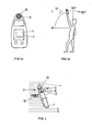
- FIG. 1a For measuring the wind speed is now the wind meter 1, as shown in FIG. 1a held in a wind flow 13, as shown schematically in FIG FIG. 2 shown. It shows FIG. 2 the wind meter 1 in cross-section, wherein the wind stream 13 flows through the open passage 11 of the wind tunnel, in which the impeller 5 is arranged freely rotatably.
- the wind meter In this case, the wind meter is arranged inclined in the air stream 13, whereby behind the upper edge 15, a congestion effect is observed, which leads to vortex formation 17.
- the effect can be explained by a vortex formation in the lee of the housing or a speed increase of the air flow.
- the oblique position leads to increased air velocities behind the impeller 5. This causes according to Bernoulli a negative pressure, that is, the pressure gradient between the front of the air duct and Back is rising. This in turn leads to increased air velocities on the impeller 5 and therefore to an increased speed.
- this property can now be used selectively to linearize the curve in a wide swivel range.
- a cover at least at the incoming air flow.
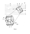
- FIG. 3 shown opposite direction front and rear of the air flow 13 can be targeted covered. This is done by covers 21 at the entrance of the air flow in the wind tunnel 11 and in the opposite direction rear by the placement of a cover 23.
- FIG. 3 shows FIG. 3 on the one hand in section, partially the wind measuring channel 11, formed by the cylindrical tube 4, and the concentric and freely rotatable impeller 5 arranged in the tube FIG. 3 is shown in perspective an embodiment of the wind meter 3.
- FIG. 4 the measured values are shown for 3 different measuring arrangements; wherein the angle of attack according to FIG. 1b is specified.
- Curve 31 shows the rotational frequency ( ⁇ / s) of the impeller as a function of the angle of inclination for an impeller without tube enclosure 4.
- Curve 35 shows the frequency with a coverage of 25% of the inlet and outlet cross-section of the air duct and
- Curve 37 shows the frequency at 33.3 percent area coverage of the input and output cross-section of the passageway 11th
- FIG. 3 illustrated example of a cover for an inventive wind meter is of course only an example to explain the present invention understandable.
- covers for example, only one cover at the input cross-section, two covers, which are arranged for example in opposite directions front and rear in the air duct covers, which cover only 10% each of the input and output cross-section, or 20%, 25th %, 30% or even 35%.
- a cover is provided at least in the input cross-section to the through-channel in which an impeller is arranged, wherein preferably this cover is arranged expansively from the cross-sectional edge towards the center, which is generally inclined towards the air flow.
Landscapes
- Physics & Mathematics (AREA)
- General Physics & Mathematics (AREA)
- Fluid Mechanics (AREA)
- Engineering & Computer Science (AREA)
- Aviation & Aerospace Engineering (AREA)
- Indicating Or Recording The Presence, Absence, Or Direction Of Movement (AREA)
Abstract
Description
- Die vorliegende Erfindung betrifft ein Windmessgerät gemäss dem Obergriff nach Anspruch 1.
- Windmessgeräte wie insbesondere Windräder zum Messen der Windgeschwindigkeit sind bekannt. So beschreiben beispielsweise das
EP 1 596 062 ,GB 765 206 US 5 939 645 Messgeräte zum Bestimmen der Windgeschwindigkeit, wobei ein Flügelrad in einem zylindrischen bzw. rohrförmigen Windkanal konzentrisch gelagert, frei drehbar angeordnet ist. Dabei wird das zylinderartige Rohr mit dem drehbaren Flügelrad in den Windstrom gebracht und die Windgeschwindigkeit durch die Rotation des Flügelrades bestimmt. - Es hat sich nun gezeigt, dass bei unterschiedlicher Neigung des rohrförmigen Kanals abweichende Messresultate ermittelt werden, das heisst, die oben beschriebenen Windmessgeräte haben den Nachteil, dass die resultierende Drehzahl des Flügelrades abhängig vom Winkel ist, mit welchem der rohrförmige Kanal in den Windstrom eingegeben wird.
- Es ist daher eine Aufgabe der vorliegenden Erfindung ein Windmessgerät, aufweisend ein Flügelrad vorzuschlagen, bei welchem die ermittelte Windgeschwindigkeit weitgehendst oder mindestens zu einem grossen Teil unabhängig ist von der Neigung mit der das Gerät von einer Benutzerperson in den Wind gebracht wird. Die Windrichtungsabhängigkeit bezüglich der Windrichtung bleibt selbstverständlich erhalten.
- Erfindungsgemäss wird die gestellte Aufgabe mittels einem Windmessgerät nach Anspruch 1 gelöst.
- Vorgeschlagen wird, dass das Windmessgerät, aufweisend ein in einem rohrförmigen Kanal angeordnetes freidrehbares Flügelrad zum Messen der Windgeschwindigkeit im Eingangsquerschnitt des rohrförmigen Kanals, eine Abdeckung aufweist, welche den Querschnitt teilweise abdeckt.
- Gemäss einer weiteren Ausführungsvariante wird vorgeschlagen, sowohl im Eingangsquerschnitt des rohrförmigen Kanales wie auch am Ausgangsquerschnitt je eine Abdeckung anzuordnen, welche zueinander gegenläufig angeordnet sind.
- Die Abdeckung, je des Querschnittes, kann bezogen auf die Gesamtfläche des Querschnittes bis zu 35% betragen.
- Vorgeschlagene Varianten weisen eine Abdeckung auf, welche beispielsweise bezogen auf die Gesamtfläche 10% - 25% des Ein- und Ausgangsquerschnittes abdecken, wobei selbstverständlich die Grösse der Abdeckung auch weniger als 10% oder mehr als 25% betragen kann.
- Die Abdeckung kann in der Querschnittsebene des Rohreinganges oder Rohrausganges liegen, oder aber vom Rohrinnern gesehen, auswärts angewinkelt verlaufend, wobei die auswärtsverlaufende Abdeckung auch gegen das Zentrum hin gebogen ausgebildet sein kann.
- Weitere mögliche Ausführungsvarianten des erfindungsgemässen Windmessgerätes sind in den abhängigen Ansprüchen charakterisiert.
- Die Erfindung wird nun beispielsweise und unter Bezug auf die beigefügten Figuren näher erläutert.
- Dabei zeigen:
-
Figur 1a ein herkömmliches Windmessgerät in Front-Draufsicht, -
Figur 1b Schematisch die übliche Gebrauchslage des Messgerätes mit der Definition der Winkel -
Figur 2 einen Querschnitt durch das Windmessgerät, angewinkelt in einem Windstrom, -
Figur 3 auszugsweise den Windmessbereich eines Windmessgerätes, aufweisend erfindungsgemäss vorgeschlagene Abdeckungen und -
Figur 4 anhand eines Diagrames die Auswirkungen der erfindungsgemässen Abdeckungen auf die gemessene Windgeschwindigkeit. -
Figur 1 zeigt in Front-Draufsicht ein herkömmliches Windmessgerät 1, aufweisend im oberen Bereich einen Windmesskanal 3, in welchem ein Flügelrad 5 angeordnet ist. - Die vom Windmessgerät 1 ermittelte Windgeschwindigkeit kann beispielsweise an einem Display 7 dargestellt werden.
- Zum Messen der Windgeschwindigkeit wird nun das Windmessgerät 1, wie dargestellt in
Figur 1a in einen Windstrom 13 gehalten, wie schematisch inFigur 2 dargestellt. Dabei zeigtFigur 2 das Windmessgerät 1 im Querschnitt, wobei der Windstrom 13 durch den offenen Durchgang 11 des Windkanals strömt, im welchem das Flügelrad 5 frei drehbar angeordnet ist. InFigur 2 ist dabei das Windmessgerät geneigt im Luftstrom 13 angeordnet, wodurch hinter der oberen Kante 15 ein Staueffekt zu beobachten ist, was zu Wirbelbildung 17 führt. Der Effekt lässt sich durch eine Wirbelbildung im Lee des Gehäuses oder eine Geschwindigkeitserhöhung des Luftstromes erklären. Die Schräglage führt zu erhöhten Luftgeschwindigkeiten hinter dem Flügelrad 5. Dies bewirkt nach Bernoulli einen Unterdruck, das heisst das Druckgefälle zwischen Vorderseite des Luftkanales und Rückseite steigt an. Dies wiederum führt zu erhöhten Luftgeschwindigkeiten am Flügelrad 5 und deshalb zu einer erhöhten Drehzahl. - Erfindungsgemäss kann diese Eigenschaft nun gezielt genutzt werden, um die Kurve in einem weiten Schwenkbereich zu linearisieren. Erfindungsgemäss vorgeschlagen wird, mindestens beim eintrendenden Luftstrom eine Abdeckung vorzusehen. Wie schematisch in
Figur 3 dargestellt, kann gegenläufig vorne und hinten der Luftstrom 13 gezielt abgedeckt werden. Dies erfolgt durch Abdeckungen 21 am Eingang des Luftstromes im Windkanal 11 und gegenläufig hinten durch das Anordnen einer Abdeckung 23. Dabei zeigtFigur 3 einerseits im Schnitt ausschnittsweise den Windmesskanal 11, gebildet durch das zylinderförmige Rohr 4, sowie das im Rohr konzentrisch und frei drehbar angeordnete Flügelrad 5. Ebenfalls inFigur 3 ist in Perspektive eine Ausführungsvariante des Windmessgerätes 3 dargestellt. - Mit der richtigen Wahl der Abdeckungen 21 und 23 erhält man beispielsweise in einem Bereich von 90° bis 60° eine weitgehend lineare Kurve.
- Anhand des Diagrammes, dargestellt in
Figur 4 , soll gezeigt werden, welchen Einfluss die Abdeckungen auf die vom Flügelrad 5 gemessene Luftgeschwindigkeit hat. Dabei wird die Luftgeschwindigkeit durch die Frequenz (u/s) des Flügelrades dargestellt und andererseits werden die Werte in Abhängigkeit des Neigewinkels des Windmessgerätes in Bezug auf die Windrichtung dargestellt, analog der Darstellung gemässFigur 1b . - In
Figur 4 sind die Messwerte für 3 verschiedene Messanordnungen dargestellt; wobei der Anströmwinkel gemässFigur 1b angegeben ist. - Kurve 31 zeigt die Drehfrequenz (u/s) des Flügelrades in Abhängigkeit des Neigewinkels für ein Flügelrad ohne Rohreinfassung 4.
- Kurve 35 zeigt die Frequenz bei einer Abdeckung von 25% des Eingangs- und Ausgangsquerschnittes des Luftkanales und
- Kurve 37 zeigt die Frequenz bei 33,3 prozentiger Flächenabdeckung des Eingangs- und Ausgangsquerschnittes des Durchgangskanals 11.
- Dabei zeigt sich deutlich, dass die beiden Kurven 35 und 37 wesentlich flacher ausgebildet sind als die Kurve 31, was auf eine Linearisierung der Durchgangsgeschwindigkeit durch das Windmessgerät schliessen lässt.
- Bei dem in
Figur 3 dargestellten Beispiel einer Abdeckung für ein erfindungsgemässes Windmessgerät handelt es sich selbstverständlich nur um ein Beispiel, um die vorliegende Erfindung verständlich darzulegen. Selbstverständlich ist es möglich, unterschiedliche Abdeckungen zu wählen, beispielsweise nur eine Abdeckung beim Eingangsquerschnitt, zwei Abdeckungen, welche beispielsweise gegenläufig vorne und hinten im Luftkanal angeordnet sind, Abdeckungen, welche nur 10% je des Eingangs- und Ausgangsquerschnittes bedecken, oder 20%, 25%, 30% oder gar 35%. Letztendlich ist es eine Frage der Optimierung der Gehäusegrösse des Windmessgerätes, der Grösse des Durchgangskanales, der Art des Flügelrades, der Bereich im welchem ein Windmessgerät in der Regel geneigt in den Windstrom behalten wird, etc. - Erfindungswesentlich ist, dass mindestens im Eingangsquerschnitt zum Durchgangskanal, in welchem ein Flügelrad angeordnet ist, eine Abdeckung vorgesehen ist, wobei bevorzugt diese Abdeckung von derjenigen Querschnittskante gegen das Zentrum hin sich ausdehnend angeordnet ist, welche in der Regel gegen den Luftstrom hin geneigt wird.
Claims (7)
- Windmessgerät (3) aufweisend in einem rohrförmigen Kanal (4,11) angeordnetes achsgelagertes, freidrehbares Flügelrad (5) zum Messen der Windgeschwindigkeit, dadurch gekennzeichnet, dass der Eingangsquerschnitt des rohrförmigen Kanals (11) teilweise abgedeckt ist.
- Windmessgerät nach Anspruch 1, dadurch gekennzeichnet, dass der Durchgangskanal (11) sowohl eingangseitig wie auch rückseitig je zueinander gegenläufig teilweise abgedeckt ist.
- Windmessgerät nach Anspruch 1 oder 2, dadurch gekennzeichnet, dass die Abdeckung eingangseitig von derjenigen Querschnittskante gegen das Zentrum hin verlaufend ausgebildet ist, welche vorgesehen ist, um gegen die Windrichtung geneigt zu werden.
- Windmessgerät nach einem der Ansprüche 1 bis 3,
dadurch gekennzeichnet, dass der Kanalquerschnitt bis ca. 35% bezogen auf die Querschnittsfläche abgedeckt ist. - Windmessgerät nach einem der Ansprüche 1 bis 4,
dadurch gekennzeichnet, dass die Querschnittsfläche ca. 10% - 25%, bezogen auf die Gesamtfläche, abgedeckt ist. - Windmessgerät nach einem der Ansprüche 1 bis 5,
dadurch gekennzeichnet, dass die Abdeckung vom Kanalinnern gesehen, schräg nach aussen verlaufend ausgebildet ist, vorzugsweise von der Kante zum Zentrum hin einwärts gebogen. - Windmessgerät nach einem der Ansprüche 1 bis 6,
dadurch gekennzeichnet, dass der Kanal zylinderförmig ausgebildet ist mit kreisförmiger Eingangs- und Ausgangsquerschnittsfläche und wobei die Abdeckung kreissegmentartig ausgebildet ist.
Applications Claiming Priority (1)
| Application Number | Priority Date | Filing Date | Title |
|---|---|---|---|
| CH18422009A CH702327A2 (de) | 2009-12-01 | 2009-12-01 | Windmessgerät. |
Publications (3)
| Publication Number | Publication Date |
|---|---|
| EP2336787A2 true EP2336787A2 (de) | 2011-06-22 |
| EP2336787A3 EP2336787A3 (de) | 2012-05-30 |
| EP2336787B1 EP2336787B1 (de) | 2014-03-05 |
Family
ID=43302031
Family Applications (1)
| Application Number | Title | Priority Date | Filing Date |
|---|---|---|---|
| EP20100189214 Not-in-force EP2336787B1 (de) | 2009-12-01 | 2010-10-28 | Windmessgerät |
Country Status (2)
| Country | Link |
|---|---|
| EP (1) | EP2336787B1 (de) |
| CH (1) | CH702327A2 (de) |
Cited By (2)
| Publication number | Priority date | Publication date | Assignee | Title |
|---|---|---|---|---|
| CN115683242A (zh) * | 2022-10-19 | 2023-02-03 | 西安京兆电力科技有限公司 | 一种非均匀风场矩形风道的风量测量系统 |
| EP4513148A1 (de) * | 2023-08-22 | 2025-02-26 | Testo SE & Co. KGaA | Strömungssonde und verwendung eines rotors |
Families Citing this family (1)
| Publication number | Priority date | Publication date | Assignee | Title |
|---|---|---|---|---|
| RU197202U1 (ru) * | 2019-12-30 | 2020-04-13 | Общество с ограниченной ответственностью "Газпром добыча Уренгой" | Стенд для проверки крыльчатки анемометра |
Citations (3)
| Publication number | Priority date | Publication date | Assignee | Title |
|---|---|---|---|---|
| GB765206A (en) | 1954-08-10 | 1957-01-02 | Nat Res Dev | Improvements in or relating to anemometers or flow-meters for measuring the speed orflow of air or gas |
| US5939645A (en) | 1997-04-17 | 1999-08-17 | Nielsen-Kellerman | Vane anemometer having a modular impeller assembly |
| EP1596062A1 (de) | 2004-05-14 | 2005-11-16 | Flytec AG | Thermische Stabilisierung eines Windrades |
Family Cites Families (1)
| Publication number | Priority date | Publication date | Assignee | Title |
|---|---|---|---|---|
| DE9110946U1 (de) * | 1991-09-04 | 1991-10-31 | Kaindl, Michael, 8000 München | Windmeßgerät (Anemometer) |
-
2009
- 2009-12-01 CH CH18422009A patent/CH702327A2/de not_active Application Discontinuation
-
2010
- 2010-10-28 EP EP20100189214 patent/EP2336787B1/de not_active Not-in-force
Patent Citations (3)
| Publication number | Priority date | Publication date | Assignee | Title |
|---|---|---|---|---|
| GB765206A (en) | 1954-08-10 | 1957-01-02 | Nat Res Dev | Improvements in or relating to anemometers or flow-meters for measuring the speed orflow of air or gas |
| US5939645A (en) | 1997-04-17 | 1999-08-17 | Nielsen-Kellerman | Vane anemometer having a modular impeller assembly |
| EP1596062A1 (de) | 2004-05-14 | 2005-11-16 | Flytec AG | Thermische Stabilisierung eines Windrades |
Cited By (2)
| Publication number | Priority date | Publication date | Assignee | Title |
|---|---|---|---|---|
| CN115683242A (zh) * | 2022-10-19 | 2023-02-03 | 西安京兆电力科技有限公司 | 一种非均匀风场矩形风道的风量测量系统 |
| EP4513148A1 (de) * | 2023-08-22 | 2025-02-26 | Testo SE & Co. KGaA | Strömungssonde und verwendung eines rotors |
Also Published As
| Publication number | Publication date |
|---|---|
| EP2336787A3 (de) | 2012-05-30 |
| EP2336787B1 (de) | 2014-03-05 |
| CH702327A2 (de) | 2011-06-15 |
Similar Documents
| Publication | Publication Date | Title |
|---|---|---|
| EP1613928B1 (de) | Differenzdruckmittel für eine gaszähleranordnung mit verbesserter strömungsgeometrie | |
| DE102010043572B4 (de) | Luftstrommessvorrichtung | |
| DE102013009347A1 (de) | Durchflussmesser | |
| DE102009001525A1 (de) | Verfahren und Wirbelströmungsmessgerät zum Überwachen und/oder Messen einer Wandströmung eines in einer Rohrleitung strömenden, zwei- oder mehrphasigen Mediums | |
| EP3006903B1 (de) | Durchflussmessvorrichtung zum Messen eines Parameters einer aus einem Fluid gebildeten Strömung | |
| DE3336911C2 (de) | ||
| EP2336787B1 (de) | Windmessgerät | |
| EP3048430A1 (de) | Gebläse mit druckmessstelle | |
| EP1288494B1 (de) | Windvektorbestimmungsgerät | |
| DE102010053261B4 (de) | Messkapsel zur Durchflussmessung | |
| EP2041523B1 (de) | Messanordnung zur strömungsmessung in einem kanal | |
| EP0109503B1 (de) | Regelventil zum Konstanthalten des Volumenstromes, insbesondere in lufttechnischen Anlagen | |
| EP0831303A2 (de) | Wirbel-Strömungsaufnehmer mit einem Turbulenzgitter | |
| EP1904812A1 (de) | Staudrucksonde | |
| DE202011105809U1 (de) | Vorrichtung zur Messung des Massestroms eines Gases | |
| DE4440683A1 (de) | Meßeinsatz für Flüssigkeitszähler | |
| EP2455724B1 (de) | Flusssensor | |
| DE202015101180U1 (de) | Manometeranordnung | |
| DE2405786A1 (de) | Messverfahren und messeinrichtung zur gasstrommessung, insbesondere in gasabsaugeleitungen | |
| DE102004055101B4 (de) | Baueinheit aus einem Strömungssensor, einem Durchlaßkanal und einem innerhalb des Durchlaßkanals angeordneten Meßkanal | |
| EP3748309A1 (de) | Ultraschalldurchflussmessgerät, verwendung eines ultraschalldurchflussmessgerätes in einem absperrorgan und absperrorgan | |
| EP2216637B1 (de) | Messrohr für eine Vorrichtung zur Abtastung eines Strömungsmittels | |
| EP2154439A1 (de) | Volumenstromregler, insbesondere für klima-und lüftungstechnische Anlagen | |
| DE102019008890A1 (de) | Durchflusszähler | |
| DE19648599C1 (de) | Wirkdruckgeber eines Durchflußmessers |
Legal Events
| Date | Code | Title | Description |
|---|---|---|---|
| PUAI | Public reference made under article 153(3) epc to a published international application that has entered the european phase |
Free format text: ORIGINAL CODE: 0009012 |
|
| AK | Designated contracting states |
Kind code of ref document: A2 Designated state(s): AL AT BE BG CH CY CZ DE DK EE ES FI FR GB GR HR HU IE IS IT LI LT LU LV MC MK MT NL NO PL PT RO RS SE SI SK SM TR |
|
| AX | Request for extension of the european patent |
Extension state: BA ME |
|
| PUAL | Search report despatched |
Free format text: ORIGINAL CODE: 0009013 |
|
| AK | Designated contracting states |
Kind code of ref document: A3 Designated state(s): AL AT BE BG CH CY CZ DE DK EE ES FI FR GB GR HR HU IE IS IT LI LT LU LV MC MK MT NL NO PL PT RO RS SE SI SK SM TR |
|
| AX | Request for extension of the european patent |
Extension state: BA ME |
|
| RIC1 | Information provided on ipc code assigned before grant |
Ipc: G01P 5/06 20060101AFI20120426BHEP |
|
| 17P | Request for examination filed |
Effective date: 20121127 |
|
| 17Q | First examination report despatched |
Effective date: 20130122 |
|
| GRAP | Despatch of communication of intention to grant a patent |
Free format text: ORIGINAL CODE: EPIDOSNIGR1 |
|
| INTG | Intention to grant announced |
Effective date: 20130920 |
|
| GRAS | Grant fee paid |
Free format text: ORIGINAL CODE: EPIDOSNIGR3 |
|
| GRAA | (expected) grant |
Free format text: ORIGINAL CODE: 0009210 |
|
| AK | Designated contracting states |
Kind code of ref document: B1 Designated state(s): AL AT BE BG CH CY CZ DE DK EE ES FI FR GB GR HR HU IE IS IT LI LT LU LV MC MK MT NL NO PL PT RO RS SE SI SK SM TR |
|
| REG | Reference to a national code |
Ref country code: GB Ref legal event code: FG4D Free format text: NOT ENGLISH |
|
| REG | Reference to a national code |
Ref country code: CH Ref legal event code: EP |
|
| REG | Reference to a national code |
Ref country code: AT Ref legal event code: REF Ref document number: 655216 Country of ref document: AT Kind code of ref document: T Effective date: 20140315 |
|
| REG | Reference to a national code |
Ref country code: CH Ref legal event code: NV Representative=s name: TROESCH SCHEIDEGGER WERNER AG, CH |
|
| REG | Reference to a national code |
Ref country code: IE Ref legal event code: FG4D Free format text: LANGUAGE OF EP DOCUMENT: GERMAN |
|
| REG | Reference to a national code |
Ref country code: DE Ref legal event code: R096 Ref document number: 502010006246 Country of ref document: DE Effective date: 20140417 |
|
| REG | Reference to a national code |
Ref country code: NL Ref legal event code: VDEP Effective date: 20140305 |
|
| PG25 | Lapsed in a contracting state [announced via postgrant information from national office to epo] |
Ref country code: LT Free format text: LAPSE BECAUSE OF FAILURE TO SUBMIT A TRANSLATION OF THE DESCRIPTION OR TO PAY THE FEE WITHIN THE PRESCRIBED TIME-LIMIT Effective date: 20140305 Ref country code: NO Free format text: LAPSE BECAUSE OF FAILURE TO SUBMIT A TRANSLATION OF THE DESCRIPTION OR TO PAY THE FEE WITHIN THE PRESCRIBED TIME-LIMIT Effective date: 20140605 |
|
| REG | Reference to a national code |
Ref country code: LT Ref legal event code: MG4D |
|
| PG25 | Lapsed in a contracting state [announced via postgrant information from national office to epo] |
Ref country code: CY Free format text: LAPSE BECAUSE OF FAILURE TO SUBMIT A TRANSLATION OF THE DESCRIPTION OR TO PAY THE FEE WITHIN THE PRESCRIBED TIME-LIMIT Effective date: 20140305 Ref country code: FI Free format text: LAPSE BECAUSE OF FAILURE TO SUBMIT A TRANSLATION OF THE DESCRIPTION OR TO PAY THE FEE WITHIN THE PRESCRIBED TIME-LIMIT Effective date: 20140305 Ref country code: SE Free format text: LAPSE BECAUSE OF FAILURE TO SUBMIT A TRANSLATION OF THE DESCRIPTION OR TO PAY THE FEE WITHIN THE PRESCRIBED TIME-LIMIT Effective date: 20140305 |
|
| PG25 | Lapsed in a contracting state [announced via postgrant information from national office to epo] |
Ref country code: HR Free format text: LAPSE BECAUSE OF FAILURE TO SUBMIT A TRANSLATION OF THE DESCRIPTION OR TO PAY THE FEE WITHIN THE PRESCRIBED TIME-LIMIT Effective date: 20140305 Ref country code: LV Free format text: LAPSE BECAUSE OF FAILURE TO SUBMIT A TRANSLATION OF THE DESCRIPTION OR TO PAY THE FEE WITHIN THE PRESCRIBED TIME-LIMIT Effective date: 20140305 Ref country code: RS Free format text: LAPSE BECAUSE OF FAILURE TO SUBMIT A TRANSLATION OF THE DESCRIPTION OR TO PAY THE FEE WITHIN THE PRESCRIBED TIME-LIMIT Effective date: 20140305 |
|
| PG25 | Lapsed in a contracting state [announced via postgrant information from national office to epo] |
Ref country code: BG Free format text: LAPSE BECAUSE OF FAILURE TO SUBMIT A TRANSLATION OF THE DESCRIPTION OR TO PAY THE FEE WITHIN THE PRESCRIBED TIME-LIMIT Effective date: 20140605 Ref country code: IS Free format text: LAPSE BECAUSE OF FAILURE TO SUBMIT A TRANSLATION OF THE DESCRIPTION OR TO PAY THE FEE WITHIN THE PRESCRIBED TIME-LIMIT Effective date: 20140705 Ref country code: RO Free format text: LAPSE BECAUSE OF FAILURE TO SUBMIT A TRANSLATION OF THE DESCRIPTION OR TO PAY THE FEE WITHIN THE PRESCRIBED TIME-LIMIT Effective date: 20140305 Ref country code: CZ Free format text: LAPSE BECAUSE OF FAILURE TO SUBMIT A TRANSLATION OF THE DESCRIPTION OR TO PAY THE FEE WITHIN THE PRESCRIBED TIME-LIMIT Effective date: 20140305 Ref country code: EE Free format text: LAPSE BECAUSE OF FAILURE TO SUBMIT A TRANSLATION OF THE DESCRIPTION OR TO PAY THE FEE WITHIN THE PRESCRIBED TIME-LIMIT Effective date: 20140305 Ref country code: NL Free format text: LAPSE BECAUSE OF FAILURE TO SUBMIT A TRANSLATION OF THE DESCRIPTION OR TO PAY THE FEE WITHIN THE PRESCRIBED TIME-LIMIT Effective date: 20140305 |
|
| PG25 | Lapsed in a contracting state [announced via postgrant information from national office to epo] |
Ref country code: ES Free format text: LAPSE BECAUSE OF FAILURE TO SUBMIT A TRANSLATION OF THE DESCRIPTION OR TO PAY THE FEE WITHIN THE PRESCRIBED TIME-LIMIT Effective date: 20140305 Ref country code: SK Free format text: LAPSE BECAUSE OF FAILURE TO SUBMIT A TRANSLATION OF THE DESCRIPTION OR TO PAY THE FEE WITHIN THE PRESCRIBED TIME-LIMIT Effective date: 20140305 Ref country code: PL Free format text: LAPSE BECAUSE OF FAILURE TO SUBMIT A TRANSLATION OF THE DESCRIPTION OR TO PAY THE FEE WITHIN THE PRESCRIBED TIME-LIMIT Effective date: 20140305 |
|
| REG | Reference to a national code |
Ref country code: DE Ref legal event code: R097 Ref document number: 502010006246 Country of ref document: DE |
|
| PG25 | Lapsed in a contracting state [announced via postgrant information from national office to epo] |
Ref country code: PT Free format text: LAPSE BECAUSE OF FAILURE TO SUBMIT A TRANSLATION OF THE DESCRIPTION OR TO PAY THE FEE WITHIN THE PRESCRIBED TIME-LIMIT Effective date: 20140707 |
|
| PLBE | No opposition filed within time limit |
Free format text: ORIGINAL CODE: 0009261 |
|
| STAA | Information on the status of an ep patent application or granted ep patent |
Free format text: STATUS: NO OPPOSITION FILED WITHIN TIME LIMIT |
|
| PG25 | Lapsed in a contracting state [announced via postgrant information from national office to epo] |
Ref country code: DK Free format text: LAPSE BECAUSE OF FAILURE TO SUBMIT A TRANSLATION OF THE DESCRIPTION OR TO PAY THE FEE WITHIN THE PRESCRIBED TIME-LIMIT Effective date: 20140305 |
|
| 26N | No opposition filed |
Effective date: 20141208 |
|
| REG | Reference to a national code |
Ref country code: DE Ref legal event code: R097 Ref document number: 502010006246 Country of ref document: DE Effective date: 20141208 |
|
| PG25 | Lapsed in a contracting state [announced via postgrant information from national office to epo] |
Ref country code: IT Free format text: LAPSE BECAUSE OF FAILURE TO SUBMIT A TRANSLATION OF THE DESCRIPTION OR TO PAY THE FEE WITHIN THE PRESCRIBED TIME-LIMIT Effective date: 20140305 |
|
| REG | Reference to a national code |
Ref country code: DE Ref legal event code: R119 Ref document number: 502010006246 Country of ref document: DE |
|
| PG25 | Lapsed in a contracting state [announced via postgrant information from national office to epo] |
Ref country code: LU Free format text: LAPSE BECAUSE OF FAILURE TO SUBMIT A TRANSLATION OF THE DESCRIPTION OR TO PAY THE FEE WITHIN THE PRESCRIBED TIME-LIMIT Effective date: 20141028 Ref country code: MC Free format text: LAPSE BECAUSE OF FAILURE TO SUBMIT A TRANSLATION OF THE DESCRIPTION OR TO PAY THE FEE WITHIN THE PRESCRIBED TIME-LIMIT Effective date: 20140305 Ref country code: SI Free format text: LAPSE BECAUSE OF FAILURE TO SUBMIT A TRANSLATION OF THE DESCRIPTION OR TO PAY THE FEE WITHIN THE PRESCRIBED TIME-LIMIT Effective date: 20140305 |
|
| REG | Reference to a national code |
Ref country code: CH Ref legal event code: PL |
|
| GBPC | Gb: european patent ceased through non-payment of renewal fee |
Effective date: 20141028 |
|
| PG25 | Lapsed in a contracting state [announced via postgrant information from national office to epo] |
Ref country code: BE Free format text: LAPSE BECAUSE OF NON-PAYMENT OF DUE FEES Effective date: 20141031 |
|
| REG | Reference to a national code |
Ref country code: IE Ref legal event code: MM4A |
|
| PG25 | Lapsed in a contracting state [announced via postgrant information from national office to epo] |
Ref country code: LI Free format text: LAPSE BECAUSE OF NON-PAYMENT OF DUE FEES Effective date: 20141031 Ref country code: DE Free format text: LAPSE BECAUSE OF NON-PAYMENT OF DUE FEES Effective date: 20150501 Ref country code: CH Free format text: LAPSE BECAUSE OF NON-PAYMENT OF DUE FEES Effective date: 20141031 Ref country code: GB Free format text: LAPSE BECAUSE OF NON-PAYMENT OF DUE FEES Effective date: 20141028 |
|
| REG | Reference to a national code |
Ref country code: FR Ref legal event code: ST Effective date: 20150630 |
|
| PG25 | Lapsed in a contracting state [announced via postgrant information from national office to epo] |
Ref country code: FR Free format text: LAPSE BECAUSE OF NON-PAYMENT OF DUE FEES Effective date: 20141031 |
|
| PG25 | Lapsed in a contracting state [announced via postgrant information from national office to epo] |
Ref country code: IE Free format text: LAPSE BECAUSE OF NON-PAYMENT OF DUE FEES Effective date: 20141028 |
|
| PG25 | Lapsed in a contracting state [announced via postgrant information from national office to epo] |
Ref country code: SM Free format text: LAPSE BECAUSE OF FAILURE TO SUBMIT A TRANSLATION OF THE DESCRIPTION OR TO PAY THE FEE WITHIN THE PRESCRIBED TIME-LIMIT Effective date: 20140305 |
|
| PG25 | Lapsed in a contracting state [announced via postgrant information from national office to epo] |
Ref country code: GR Free format text: LAPSE BECAUSE OF FAILURE TO SUBMIT A TRANSLATION OF THE DESCRIPTION OR TO PAY THE FEE WITHIN THE PRESCRIBED TIME-LIMIT Effective date: 20140606 |
|
| PG25 | Lapsed in a contracting state [announced via postgrant information from national office to epo] |
Ref country code: MT Free format text: LAPSE BECAUSE OF FAILURE TO SUBMIT A TRANSLATION OF THE DESCRIPTION OR TO PAY THE FEE WITHIN THE PRESCRIBED TIME-LIMIT Effective date: 20140305 Ref country code: HU Free format text: LAPSE BECAUSE OF FAILURE TO SUBMIT A TRANSLATION OF THE DESCRIPTION OR TO PAY THE FEE WITHIN THE PRESCRIBED TIME-LIMIT; INVALID AB INITIO Effective date: 20101028 Ref country code: TR Free format text: LAPSE BECAUSE OF FAILURE TO SUBMIT A TRANSLATION OF THE DESCRIPTION OR TO PAY THE FEE WITHIN THE PRESCRIBED TIME-LIMIT Effective date: 20140305 |
|
| REG | Reference to a national code |
Ref country code: AT Ref legal event code: MM01 Ref document number: 655216 Country of ref document: AT Kind code of ref document: T Effective date: 20151028 |
|
| PG25 | Lapsed in a contracting state [announced via postgrant information from national office to epo] |
Ref country code: AT Free format text: LAPSE BECAUSE OF NON-PAYMENT OF DUE FEES Effective date: 20151028 |
|
| PG25 | Lapsed in a contracting state [announced via postgrant information from national office to epo] |
Ref country code: MK Free format text: LAPSE BECAUSE OF FAILURE TO SUBMIT A TRANSLATION OF THE DESCRIPTION OR TO PAY THE FEE WITHIN THE PRESCRIBED TIME-LIMIT Effective date: 20140305 |
|
| PG25 | Lapsed in a contracting state [announced via postgrant information from national office to epo] |
Ref country code: AL Free format text: LAPSE BECAUSE OF FAILURE TO SUBMIT A TRANSLATION OF THE DESCRIPTION OR TO PAY THE FEE WITHIN THE PRESCRIBED TIME-LIMIT Effective date: 20140305 |