EP2336861A2 - Appareil de détection d'objet multi-tactile et proche à l'aide d'un réseau de détection - Google Patents
Appareil de détection d'objet multi-tactile et proche à l'aide d'un réseau de détection Download PDFInfo
- Publication number
- EP2336861A2 EP2336861A2 EP10190481A EP10190481A EP2336861A2 EP 2336861 A2 EP2336861 A2 EP 2336861A2 EP 10190481 A EP10190481 A EP 10190481A EP 10190481 A EP10190481 A EP 10190481A EP 2336861 A2 EP2336861 A2 EP 2336861A2
- Authority
- EP
- European Patent Office
- Prior art keywords
- diffuser
- invisible light
- light source
- sensing apparatus
- visible light
- Prior art date
- Legal status (The legal status is an assumption and is not a legal conclusion. Google has not performed a legal analysis and makes no representation as to the accuracy of the status listed.)
- Withdrawn
Links
Images


Classifications
-
- G—PHYSICS
- G06—COMPUTING OR CALCULATING; COUNTING
- G06F—ELECTRIC DIGITAL DATA PROCESSING
- G06F3/00—Input arrangements for transferring data to be processed into a form capable of being handled by the computer; Output arrangements for transferring data from processing unit to output unit, e.g. interface arrangements
- G06F3/01—Input arrangements or combined input and output arrangements for interaction between user and computer
- G06F3/03—Arrangements for converting the position or the displacement of a member into a coded form
- G06F3/041—Digitisers, e.g. for touch screens or touch pads, characterised by the transducing means
- G06F3/042—Digitisers, e.g. for touch screens or touch pads, characterised by the transducing means by opto-electronic means
-
- G—PHYSICS
- G06—COMPUTING OR CALCULATING; COUNTING
- G06F—ELECTRIC DIGITAL DATA PROCESSING
- G06F3/00—Input arrangements for transferring data to be processed into a form capable of being handled by the computer; Output arrangements for transferring data from processing unit to output unit, e.g. interface arrangements
- G06F3/01—Input arrangements or combined input and output arrangements for interaction between user and computer
- G06F3/03—Arrangements for converting the position or the displacement of a member into a coded form
- G06F3/033—Pointing devices displaced or positioned by the user, e.g. mice, trackballs, pens or joysticks; Accessories therefor
- G06F3/038—Control and interface arrangements therefor, e.g. drivers or device-embedded control circuitry
- G06F3/0386—Control and interface arrangements therefor, e.g. drivers or device-embedded control circuitry for light pen
-
- G—PHYSICS
- G06—COMPUTING OR CALCULATING; COUNTING
- G06F—ELECTRIC DIGITAL DATA PROCESSING
- G06F2203/00—Indexing scheme relating to G06F3/00 - G06F3/048
- G06F2203/041—Indexing scheme relating to G06F3/041 - G06F3/045
- G06F2203/04109—FTIR in optical digitiser, i.e. touch detection by frustrating the total internal reflection within an optical waveguide due to changes of optical properties or deformation at the touch location
Definitions
- the present invention relates to a multi-touch and proximate object sensing apparatus using sensing array.
- Example embodiments of the present disclosure relate to a multi-touch sensing apparatus that may sense a touch image or a target image using a sensing array.
- planar light may not be uniform.
- a structure where a diffuser is omitted and an Infrared Ray (IR) sensor is included to sense an object that is located on or above an LCD display has been provided.
- IR Infrared Ray
- a multi-touch and proximate object sensing apparatus that may change a location of a light source to sense a touch of an object, and change a shape of the object without degrading an image quality is desired. Also, since a touch panel display is often used in a portable device, a structure that may reduce a thickness of the touch sensing apparatus is desired.
- a sensing apparatus including: a diffuser where an invisible light is projected; a visible light source, arranged below the diffuser, to emit a visible light to the diffuser; and a sensing array, arranged below the diffuser, to sense the invisible light which is projected to the diffuser.
- the sensing apparatus may further include an invisible light source, arranged above the diffuser, to emit the invisible light to sense a touch image or a target image, the touch image or the target image being generated by an object.
- an invisible light source arranged above the diffuser, to emit the invisible light to sense a touch image or a target image, the touch image or the target image being generated by an object.
- the sensing apparatus may further include a light guide, arranged above the diffuser, to totally and internally reflect the invisible light emitted from the invisible light source.
- the invisible light source may emit the invisible light to an inside of the light guide or to the object.
- the object may be arranged above the light guide or may be spaced apart from an upper side of the light guide by a predetermined distance, and the sensing array may sense the invisible light reflected by the object.
- the sensing array may sense a location where the total internal reflection is prevented by the object.
- the invisible light source may be spaced apart from the diffuser by a predetermined distance and emit the invisible light to sense the touch image to the diffuser. In this instance, the invisible light source may emit the invisible light vertical to the diffuser or by a predetermined angle to the diffuser.
- the visible light source may be arranged below and vertical to the diffuser, and emit the visible light directly to the diffuser.
- the visible light source may be arranged below an edge of the diffuser, and emit the visible light to the diffuser by reflecting the visible light through a waveguide.
- a sensing apparatus including: a diffuser where an invisible light is projected; and a sensing array, arranged below the diffuser, to sense the invisible light which is projected to the diffuser.
- the sensing apparatus may further include: an invisible light source, arranged above the diffuser, to emit the invisible light to sense a touch image or a target image, the touch image or the target image being generated by an object.
- an invisible light source arranged above the diffuser, to emit the invisible light to sense a touch image or a target image, the touch image or the target image being generated by an object.
- the invisible light source may emit the invisible light vertically to the diffuser or may emit the invisible light by a predetermined angle with the diffuser.
- a sensing apparatus including: an Organic Light Emitting Diode (OLED) to emit a visible light, an OLED panel where the OLED is arranged, an invisible light source, arranged above the OLED panel, to project invisible light towards the OLED panel, and a sensing array, arranged below the OLED panel, to sense the invisible light that is projected towards the OLED panel.
- OLED Organic Light Emitting Diode
- the sensing apparatus includes a diffuser, arranged below the touchable surface, an invisible light source, arranged above the diffuser, to emit an invisible light towards the diffuser, a visible light source, arranged below the diffuser, to emit a visible light towards the diffuser, a sensing array, arranged below the diffuser, to sense the invisible light, and a controller to selectively control a quantity of the visible light projected towards the diffuser.
- the sensing array may be arranged as a two-dimensional matrix of sensors to measure an invisible light intensity across one or more two dimensional coordinates of the touchable surface.
- the sensing apparatus may further include a display configured to display an image that is viewable on the touchable surface.
- the change in appearance of the portion of the displayed image may include a change in brightness of the portion of the displayed image, which brightness is changed by changing a quantity of the visible light projected towards the diffuser.
- the controller may control the quantity of the visible light corresponding to an area of the touch depending on an intensity of the touch.
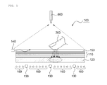
- FIG. 1 illustrates a multi-touch and proximate object sensing apparatus 100 where an invisible light source is arranged at an edge of the multi-touch and proximate object sensing apparatus.
- the multi-touch and proximate object sensing apparatus may include, for example, a display panel 110, a diffuser 120, a visible light source 130, an invisible light source 140, a light guide 150, and a sensing array 160.
- the display panel 110 may be arranged in an upper portion, e.g., in an upper layer of the sensing apparatus 100.
- the display panel 110 may be a Liquid Crystal Display (LCD) panel.
- the display panel 110 may have a touchable surface, while also being able to display a graphic image viewable via the touchable surface.
- the diffuser 120 may be arranged below the display panel 110. Also, the diffuser 120 may emit visible light in a planar form by diffusing, spreading out, or scattering the visible light incident from the visible light source 130. Here, the visible light, emitted from the visible light source 130, or an invisible light, emitted from the invisible light source 140, may be incident on the diffuser 120.
- the diffuser 120 may emit the planar visible light incident from the visible light source 130.
- a pattern may be formed to remove a hot spot with remaining uniformity of the incident light.
- the hot spot may be generated due to visible light from the visible light source 130 being focused on a predetermined portion of the diffuser 120.
- the visible light source 130 may be comprised of different types of sources such as a Cold Cathode Fluorescent Lamp (CCFL) or a Light Emitting Diode (LED) .
- the visible light source 130 emits visible light and may be arranged below and vertical to the diffuser 120. That is, the visible light source 130 may be arranged as a direct type with respect to the diffuser 120. In this instance, the visible light source 130 may directly emit the visible light, used to display an image on the display panel 110, to the diffuser 120.
- a structure where a backlight unit is removed from the display panel 110 is illustrated in FIG. 1 .
- the diffuser 120 and the visible light source 130 may function as the backlight unit. Since the backlight unit may be removed, a thickness of the sensing apparatus 100 may be reduced in comparison to a similar panel that includes a backlight.
- the visible light source 130 may be comprised of one or more of the CCFL or the LED.
- the visible light, emitted from the visible light source 130, may be changed to a planar light by way of the diffuser 120.
- the invisible light source 140 may be arranged above the diffuser 120.
- the invisible light source 140 may be arranged on a surface of the diffuser 120 that is opposite the surface of the diffuser 120 on which the visible light source 130 is arranged.
- the invisible light source 140 may emit an invisible light to sense a touch image or a target image.
- the touch image or the target image may be generated by an object, and the object may be arranged above the light guide 150 or may be spaced apart from an upper side of the light guide 150 by a predetermined distance.
- the invisible light source 140 may emit the invisible light towards an object 800 closely located above the light guide 150.
- the invisible light may include an Infrared Ray (IR) or an UltraViolet (UV).
- the invisible light source 140 may emit invisible light to sense a touch image or a target image reflected on a surface of the display panel 110 by the object 200, which is located above or on the display panel 110.
- the target image may be an image corresponding to a location of a reflection light, reflected by the object 200 located close to the upper side of the light guide 150, from among images displayed in the display panel 110.
- the reflection light may have a shape that is similar to the shape of the object 200.
- the invisible light source 140 may be arranged to emit the invisible light to an inside of the light guide 150, located above the display panel 110, or to the object 800 which is spaced apart from the upper side of the light guide 150 by a predetermined distance.
- the invisible light source 140 may be arranged at an edge of an upper portion of the display panel 110.
- the light guide 150 may totally and internally reflect the invisible light emitted from the invisible light source 140.
- the light guide 150 may be made of a transparent material such as an acryl, polycarbonate plate, and the like.
- an object such as a digit, e.g., a finger, of a user or a stick, e.g., a stylus, is located on or above the display panel 110, total internal reflection occurring inside the light guide 150 due to the object may be prevented.
- the sensing array 160 may be arranged below the diffuser 120 to sense the invisible light projected from the invisible light source 140 towards the diffuser 120 or to sense invisible light reflected by an object such as object 200.
- the sensing array 160 may identify a location of the invisible light that is reflected by the object 200 and projected to the diffuser 120, and may sense the touch image corresponding to the identified location.
- the sensing array 160 may identify a location of the invisible light that is reflected by the object 800 and directly projected or transmitted to the diffuser 120, and may sense the target image corresponding to the identified location.
- the target image may be a reflection light image projected or transmitted to the diffuser 120.
- the reflection light image may have a shape similar to that of the object.
- the object may be located close to the light guide 150 to enable the invisible light source 140 to emit the invisible light to the object.
- the sensing array 160 may identify a location where the total internal reflection is prevented in the light guide 150, and sense the touch image corresponding to the identified location.
- the sensing array 160 may include at least one invisible light sensor to sense the invisible light.
- the invisible light sensor may be a photo diode or a photo transistor.
- the invisible light sensor may be arranged in matrix form in the sensor array 160, and extract a voltage or a current that varies depending on a quantity of invisible light emitted from the invisible light source 140.
- the invisible light sensor may provide an invisible light intensity of the touch image depending on two-dimensional (2D) coordinates of the touchable surface, based on the extracted voltage or current.
- the visible light source 130 may be controlled e.g., by a controller 1000 using control information, and thereby may be selectively turned on or off.
- the quantity of the visible light may be selectively controlled by controller 1000.
- the quantity of the visible light may be varied at particular LED locations of the visible light source 130 corresponding to particular 2D coordinates of the touchable surface.
- the control information may be previously defined based on image data, obtained by the sensing array 160, and include information about a touch to the light guide 150, a shadow of the invisible light projected to the diffuser 120, and a movement of the invisible light source 140.
- the controller 1000 may control a quantity of the emitted visible light corresponding to an area of the touch depending on an intensity of the touch, thereby enhancing communication of the apparatus with the user. Also, the controller 1000 may selectively turn visible light source 130 on or off based on a movement of the touch.
- controller 1000 may control the quantity of the visible light emitted by the visible light source 130 using the movement of the invisible light source 140, which is spaced apart from the diffuser 120 by the predetermined distance, or the shadow of the invisible light projected on the diffuser 120.
- the quantity of the visible light may be controlled, e.g., by controller 1000. That is, a brightness of an image displayed on the display panel 110 may be controlled depending on the movement of the object.
- a controller e.g., an apparatus of controlling information about the LCD, and thus a user input device may be operated.
- the apparatus of controlling the information about the LCD may be a Personal Computer (PC)
- the user input device may be a mouse or a keyboard.
- the image data may be obtained when the sensing array 160 senses the invisible light reflected by the object, a shadow of the object, or the invisible light directly emitted to the diffuser 120.
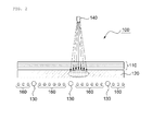
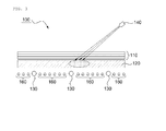
- FIGS. 2 and 3 illustrate a configuration of a sensing apparatus 100 where an invisible light source is spaced apart from the multi-touch sensing apparatus, e.g., elevated above the touch surface of the display panel.
- the sensing apparatus 100 may include, for example, the display panel 110, the diffuser 120, the visible light source 130, the invisible light source 140, and the sensing array 160.
- the display panel 110 may be arranged in an upper portion, e.g., in an upper layer of the sensing apparatus 100, and displays an image.
- the diffuser 120 may be arranged below the display panel 110, and diffuses a visible light, emitted from the visible light source 130, in a planar form.
- the visible light source 130 may be arranged below and vertical to the diffuser 120, and emits visible light. That is, the visible light source 130 may be arranged as a direct type with respect to the diffuser 120. Here, the visible light source 130 may directly emit the visible light, used to display an image on the display panel 110, to the diffuser 120.
- the invisible light source 140 may be spaced apart from the diffuser 120 by a predetermined distance. Also, the invisible light source 140 may emit an invisible light towards the diffuser 120 to sense a touch image or a target image. As illustrated in FIG. 2 , the invisible light source 140 may emit the invisible light orthogonally to an upper side of the diffuser 120, or may emit the invisible light at a predetermined angle to the upper side of the diffuser 120, e.g., at an angle offset from the orthogonal.
- the invisible light source 140 may be a lamp or a laser pointer.
- the sensing array 160 may be arranged below the diffuser 120, and may sense the invisible light projected from the invisible light source 140 to the diffuser 120.
- the sensing array 160 may identify a location of the invisible light that is reflected by the object 200 and projected to the diffuser 120, and may sense the touch image corresponding to the identified location.
- the sensing array 160 of FIG. 2 is identical to the sensing array 160 of FIG. 1 , further descriptions will be omitted.
- the sensing array 160 may sense the invisible light, projected towards the diffuser 120, and may obtain coordinates of the invisible light source 140.
- the sensing array 160 may sense the invisible light, projected to the diffuser 120 by the predetermined angle, and obtain the coordinates pointed to by the laser pointer.
- FIG. 4 illustrates a sensing apparatus 400 using a waveguide.
- FIGS. 5 and 6 illustrate a configuration of the sensing apparatus 400 using a waveguide. That is, FIGS. 4 through 6 illustrate the sensing apparatus 400 where the waveguide is added to the sensing apparatus 100 of FIGS. 1 through 3 . Components already described above with reference to FIGS. 1 through 3 will not be further described below.
- the sensing apparatus 400 may include, for example, a display panel 410, a diffuser 420, a visible light source 430, a waveguide 440, an invisible light source 450, a light guide 460, and a sensing array 470.
- the display panel 410 may be arranged in an upper portion, e.g., an upper layer, of the sensing apparatus 400, and displays an image.
- the diffuser 420 may be arranged below the display panel 410, and emits a planar visible light emitted from the visible light source 430.
- the visible light source 430 may be arranged below an edge of the diffuser 420, and emits the visible light.
- the visible light source 430 may emit the visible light, used to display an image on the display panel 410, to the diffuser 420 through the waveguide 440.
- the visible light source 430 may be arranged in an edge type with respect to the diffuser 420.
- the waveguide 440 may be arranged below the diffuser 420, and reflect the visible light, emitted from the visible light source 430, to the diffuser 420.
- the waveguide 440 may be a wedge type having different thicknesses of edges.
- a plate type having an even thickness may be used as the waveguide 440.
- the invisible light source 450 may be arranged above the diffuser 420, and emits an invisible light to sense a touch image or a target image.
- the touch image or the target image may be generated by an object.
- the light guide 460 may totally and internally reflect the invisible light emitted from the invisible light source 450.
- the sensing array 470 may be arranged below the waveguide 440, and may sense the invisible light projected from the invisible light source 450 to the diffuser 420.
- the sensing array 470 may identify a location of the invisible light that is reflected by the object 200 and projected to the diffuser 420, and may sense the touch image corresponding to the identified location. In this instance, the sensing array 470 may identify a location where the total internal reflection is prevented in the light guide 460, and sense a touch image corresponding to the identified location.
- the sensing array 470 may identify a location of the invisible light, which is reflected by the object 800 and directly projected or transmitted to the diffuser 420, and may sense a target image corresponding to the identified location.
- the sensing apparatus 400 may include, for example, the display panel 410, the diffuser 420, the visible light source 430, the waveguide 440, the invisible light source 450, and the sensing array 470.
- the display panel 410 may be arranged in an upper portion, e.g., an upper layer, of the sensing apparatus 400, and displays an image.
- the diffuser 420 may be arranged below the display panel 410, and emits a planar visible light by diffusing, spreading out, and scattering a visible light emitted from the visible light source 430.
- the visible light source 430 may be arranged below an edge of the diffuser 420, and emits visible light. In this instance, the visible light source 430 may emit the visible light to the diffuser 420 through the waveguide 440.
- the waveguide 440 may be arranged below the diffuser 420, and reflect the visible light, emitted from the visible light source 430, to the diffuser 420. Since the visible light, emitted from the visible light source 430, may be reflected through the waveguide 440, the visible light may be vertically, e.g., orthogonally, incident on the diffuser 420. That is, the visible light source 430 may be arranged in an edge type with respect to the diffuser 420.
- the invisible light source 450 may be spaced apart from the diffuser 420 by a predetermined distance, and emits an invisible light to sense a touch image or a target image to the diffuser 120. As illustrated in FIG. 5 , the invisible light source 450 may emit the invisible light to be orthogonal to an upper side of the diffuser 420. Also, as illustrated in FIG. 6 , the invisible light source 450 may emit the invisible light at a predetermined angle to the upper side of the diffuser 420, e.g. e.g., at an angle offset from the orthogonal.
- the sensing array 470 may be arranged below the diffuser 420, and may sense the invisible light projected from the invisible light source 450 to the diffuser 420.
- the sensing array 470 may sense the invisible light, projected to the diffuser 420 at the predetermined angle, and may obtain coordinates pointed to by the laser pointer.
- the sensing array 470 may sense the invisible light, vertically and downwardly emitted from the LED pointer and thereby projected to the diffuser 420, and may obtain coordinates pointed to by the LED pointer.
- the sensing array 470 may sense the touch image, the target image, or the invisible light, projected to the diffuser 420, using a plurality of invisible light sources 451 and 453 as illustrated in FIGS. 7 and 8 . That is, the sensing array 470 may sense the touch image or the target image using a reflection light reflected by an object.
- the object may be located on an upper side of the light guide 150, or close to the upper side of the light guide 150.
- the sensing array 470 may obtain the pointed to coordinates.
- the sensing array 470 may sense the touch image using a shadow, occurring when the invisible light is blocked by the object 200, as well as the invisible light reflected by the object 200. That is, as illustrated in FIG. 9 , the sensing array 470 may sense a shadow 910, occurring when the invisible light is blocked by the object 200 in the diffuser 420, and thereby may sense the touch image.
- the invisible light 450 may include a lamp or sunlight or both.
- Embodiments have been described in which a sensing apparatus senses a touch image or a target image projected to a diffuser.
- a sensing apparatus senses a touch image or a target image projected to a diffuser.
- an LCD panel when used as a display panel, an Organic Light Emitting Diode (OLED) display panel 1110 may be used.
- OLED Organic Light Emitting Diode
- an OLED may be used as a visible light source.
- the sensing apparatus 1100 may include, for example, the OLED panel 1110, the invisible light source 1140, light guide 1150, and the sensing array 1160.
- the OLED when used as the visible light source, the diffuser may be removed from the sensing apparatus 1100.
- the sensing array 1160 may be located below the OLED panel 1110 to sense an invisible light projected by the invisible light source 1140 to the OLED panel 1110 or reflected by an object such as objects 1200 or 1800.
- a visible light source and a sensing array may be arranged below a diffuser to display an image and sense a touch image, and thus a total thickness of a sensing apparatus may be reduced.
- the sensing array may be arranged below the diffuser, and thus a visible light source may not be affected by the sensing array, and image quality may be improved.
- the touch image may be sensed using a predetermined number of sensing arrays, arranged below the diffuser, and thus a price of the sensing apparatus may be reduced.
Landscapes
- Engineering & Computer Science (AREA)
- General Engineering & Computer Science (AREA)
- Theoretical Computer Science (AREA)
- Human Computer Interaction (AREA)
- Physics & Mathematics (AREA)
- General Physics & Mathematics (AREA)
- Position Input By Displaying (AREA)
Applications Claiming Priority (2)
| Application Number | Priority Date | Filing Date | Title |
|---|---|---|---|
| KR20090109734 | 2009-11-13 | ||
| KR1020100074599A KR20110053165A (ko) | 2009-11-13 | 2010-08-02 | 센싱 어레이를 이용한 멀티터치 및 근접한 오브젝트 센싱 장치 |
Publications (2)
| Publication Number | Publication Date |
|---|---|
| EP2336861A2 true EP2336861A2 (fr) | 2011-06-22 |
| EP2336861A3 EP2336861A3 (fr) | 2011-10-12 |
Family
ID=43828203
Family Applications (1)
| Application Number | Title | Priority Date | Filing Date |
|---|---|---|---|
| EP10190481A Withdrawn EP2336861A3 (fr) | 2009-11-13 | 2010-11-09 | Appareil de détection d'objet multi-tactile et proche à l'aide d'un réseau de détection |
Country Status (4)
| Country | Link |
|---|---|
| US (1) | US20110115749A1 (fr) |
| EP (1) | EP2336861A3 (fr) |
| JP (1) | JP5843438B2 (fr) |
| CN (1) | CN102063226B (fr) |
Cited By (1)
| Publication number | Priority date | Publication date | Assignee | Title |
|---|---|---|---|---|
| US11789568B2 (en) | 2018-12-28 | 2023-10-17 | Semiconductor Energy Laboratory Co., Ltd. | Display device |
Families Citing this family (12)
| Publication number | Priority date | Publication date | Assignee | Title |
|---|---|---|---|---|
| TW201133299A (en) * | 2010-03-25 | 2011-10-01 | Chunghwa Picture Tubes Ltd | Touch position identification method |
| US8674965B2 (en) * | 2010-11-18 | 2014-03-18 | Microsoft Corporation | Single camera display device detection |
| CN103677437A (zh) * | 2012-09-10 | 2014-03-26 | 原相科技股份有限公司 | 光学触控装置以及亮度校正装置 |
| TWI484389B (zh) * | 2012-10-31 | 2015-05-11 | Au Optronics Corp | 觸控顯示裝置 |
| US9223442B2 (en) * | 2013-01-10 | 2015-12-29 | Samsung Display Co., Ltd. | Proximity and touch sensing surface for integration with a display |
| CN104509210B (zh) * | 2013-02-19 | 2017-06-09 | 飞利浦灯具控股公司 | 用于控制照明的方法和装置 |
| KR102730157B1 (ko) * | 2016-11-07 | 2024-11-15 | 삼성전자주식회사 | 디스플레이 장치 및 디스플레이 방법 |
| EP3599644B1 (fr) * | 2018-07-26 | 2020-08-19 | PA.Cotte Family Holding GmbH | Affichage multifonctionnel |
| CN111081694B (zh) * | 2018-10-18 | 2022-03-22 | 群创光电股份有限公司 | 电子装置、拼接电子设备与其操作方法 |
| KR20220062284A (ko) | 2019-09-24 | 2022-05-16 | 베르-헬라 테르모콘트롤 게엠베하 | 광학적으로 작동하는 근접센서시스템이 통합된 디스플레이 장치 |
| JP2021197028A (ja) * | 2020-06-17 | 2021-12-27 | セイコーエプソン株式会社 | 位置検出方法、プロジェクターの制御方法、位置検出装置およびプロジェクター |
| JP7565180B2 (ja) * | 2020-09-18 | 2024-10-10 | 株式会社ジャパンディスプレイ | 表示装置及び殺菌装置 |
Family Cites Families (28)
| Publication number | Priority date | Publication date | Assignee | Title |
|---|---|---|---|---|
| US9513744B2 (en) * | 1994-08-15 | 2016-12-06 | Apple Inc. | Control systems employing novel physical controls and touch screens |
| JPH10260315A (ja) * | 1997-03-17 | 1998-09-29 | Dainippon Printing Co Ltd | レンズ導光板、及びそれを用いた面光源装置 |
| JP2000105671A (ja) * | 1998-05-11 | 2000-04-11 | Ricoh Co Ltd | 座標入力/検出装置および電子黒板システム |
| US6992659B2 (en) * | 2001-05-22 | 2006-01-31 | Palmone, Inc. | High transparency integrated enclosure touch screen assembly for a portable hand held device |
| US7006080B2 (en) * | 2002-02-19 | 2006-02-28 | Palm, Inc. | Display system |
| JP2004070195A (ja) * | 2002-08-09 | 2004-03-04 | Toto Ltd | タッチパネル |
| US7626575B2 (en) * | 2003-03-28 | 2009-12-01 | Samsung Electronics Co., Ltd. | Light pen |
| JP2007506180A (ja) * | 2003-09-22 | 2007-03-15 | コニンクリユケ フィリップス エレクトロニクス エヌ.ブイ. | 表示モニタのための座標検出システム |
| NO323926B1 (no) * | 2004-11-12 | 2007-07-23 | New Index As | Visuelt system samt styringsobjekt og apparat til bruk i systemet. |
| KR100631904B1 (ko) * | 2005-02-18 | 2006-10-11 | 삼성전기주식회사 | 도광 기능을 갖는 직하형 백라이트 장치 |
| US7705835B2 (en) * | 2005-03-28 | 2010-04-27 | Adam Eikman | Photonic touch screen apparatus and method of use |
| US7525538B2 (en) * | 2005-06-28 | 2009-04-28 | Microsoft Corporation | Using same optics to image, illuminate, and project |
| WO2007013272A1 (fr) * | 2005-07-28 | 2007-02-01 | Sharp Kabushiki Kaisha | Dispositif d'affichage et dispositif de rétroéclairage |
| US7874682B2 (en) * | 2006-01-28 | 2011-01-25 | Northrop Grumman Systems Corporation | Component displays and beamsplitter that form composite image |
| US7515143B2 (en) * | 2006-02-28 | 2009-04-07 | Microsoft Corporation | Uniform illumination of interactive display panel |
| JP2009545828A (ja) * | 2006-08-03 | 2009-12-24 | パーセプティブ ピクセル,インク. | 全反射妨害による多接触検知表示装置 |
| US8144271B2 (en) * | 2006-08-03 | 2012-03-27 | Perceptive Pixel Inc. | Multi-touch sensing through frustrated total internal reflection |
| US8441467B2 (en) * | 2006-08-03 | 2013-05-14 | Perceptive Pixel Inc. | Multi-touch sensing display through frustrated total internal reflection |
| US8786553B2 (en) * | 2006-10-06 | 2014-07-22 | Kyocera Corporation | Navigation pad and method of using same |
| US7924272B2 (en) * | 2006-11-27 | 2011-04-12 | Microsoft Corporation | Infrared sensor integrated in a touch panel |
| JP4356757B2 (ja) * | 2007-03-13 | 2009-11-04 | セイコーエプソン株式会社 | 液晶装置、電子機器および位置特定方法 |
| US20080224974A1 (en) * | 2007-03-16 | 2008-09-18 | Leonard Tsai | Liquid crystal display |
| JP2008241807A (ja) * | 2007-03-26 | 2008-10-09 | Seiko Epson Corp | 液晶装置及び電子機器 |
| JP2008269574A (ja) * | 2007-03-27 | 2008-11-06 | Seiko Epson Corp | タッチ式入力装置及びその制御方法 |
| KR101407300B1 (ko) * | 2007-11-19 | 2014-06-13 | 엘지디스플레이 주식회사 | 멀티 터치 평판 표시모듈 |
| JP2009140253A (ja) * | 2007-12-06 | 2009-06-25 | Funai Electric Co Ltd | 薄型表示装置 |
| US20090219253A1 (en) * | 2008-02-29 | 2009-09-03 | Microsoft Corporation | Interactive Surface Computer with Switchable Diffuser |
| KR101495164B1 (ko) * | 2008-04-10 | 2015-02-24 | 엘지전자 주식회사 | 이동단말기 및 그 화면 처리 방법 |
-
2010
- 2010-11-09 EP EP10190481A patent/EP2336861A3/fr not_active Withdrawn
- 2010-11-12 JP JP2010253937A patent/JP5843438B2/ja not_active Expired - Fee Related
- 2010-11-15 CN CN201010548490.0A patent/CN102063226B/zh not_active Expired - Fee Related
- 2010-11-15 US US12/946,411 patent/US20110115749A1/en not_active Abandoned
Non-Patent Citations (1)
| Title |
|---|
| None |
Cited By (3)
| Publication number | Priority date | Publication date | Assignee | Title |
|---|---|---|---|---|
| US11789568B2 (en) | 2018-12-28 | 2023-10-17 | Semiconductor Energy Laboratory Co., Ltd. | Display device |
| US12099686B2 (en) | 2018-12-28 | 2024-09-24 | Semiconductor Energy Laboratory Co., Ltd. | Display device |
| US12452969B2 (en) | 2018-12-28 | 2025-10-21 | Semiconductor Energy Laboratory Co., Ltd. | Display device |
Also Published As
| Publication number | Publication date |
|---|---|
| CN102063226A (zh) | 2011-05-18 |
| EP2336861A3 (fr) | 2011-10-12 |
| CN102063226B (zh) | 2015-11-25 |
| JP2011108236A (ja) | 2011-06-02 |
| US20110115749A1 (en) | 2011-05-19 |
| JP5843438B2 (ja) | 2016-01-13 |
Similar Documents
| Publication | Publication Date | Title |
|---|---|---|
| EP2336861A2 (fr) | Appareil de détection d'objet multi-tactile et proche à l'aide d'un réseau de détection | |
| EP2365423A2 (fr) | Appareil de détection d'objet tactile et objet proche par lumière de radiation sélective | |
| KR101407301B1 (ko) | 터치 패널 표시장치 | |
| US8395588B2 (en) | Touch panel | |
| US9213443B2 (en) | Optical touch screen systems using reflected light | |
| US8970556B2 (en) | Apparatus to sense touching and proximate objects | |
| US9870100B2 (en) | Multi-touch sensing apparatus using rear view camera of array type | |
| US20170098146A1 (en) | Product with coding pattern | |
| CN107111383B (zh) | 非接触输入装置及方法 | |
| CN102053763B (zh) | 光学位置检测装置及带位置检测功能的显示装置 | |
| KR20120065653A (ko) | 멀티터치 및 근접한 오브젝트 센싱이 가능한 디스플레이 장치 | |
| KR20100121257A (ko) | 멀티 인식 터치 패널 및 이를 적용한 디스플레이 장치 | |
| US20110216041A1 (en) | Touch panel and touch position detection method of touch panel | |
| US9710074B2 (en) | Digitizer using position-unique optical signals | |
| US9292131B2 (en) | Light guide for backlight | |
| US8283617B2 (en) | Display device and light sensing system | |
| US8982100B2 (en) | Interactive input system and panel therefor | |
| US9035912B2 (en) | Digitizer for multi-display system | |
| KR20080100008A (ko) | 멀티 터치 장치 | |
| JP6663736B2 (ja) | 非接触表示入力装置及び方法 | |
| KR20110053165A (ko) | 센싱 어레이를 이용한 멀티터치 및 근접한 오브젝트 센싱 장치 | |
| WO2013009723A1 (fr) | Numériseur utilisant des signaux optiques à position unique | |
| JP2011090602A (ja) | 光学式位置検出装置および位置検出機能付き表示装置 | |
| JP2010204789A (ja) | 光学式位置検出装置、位置検出機能付き表示装置、および電子機器 | |
| JP2011065511A (ja) | 光学式位置検出装置および位置検出機能付き表示装置 |
Legal Events
| Date | Code | Title | Description |
|---|---|---|---|
| PUAI | Public reference made under article 153(3) epc to a published international application that has entered the european phase |
Free format text: ORIGINAL CODE: 0009012 |
|
| AK | Designated contracting states |
Kind code of ref document: A2 Designated state(s): AL AT BE BG CH CY CZ DE DK EE ES FI FR GB GR HR HU IE IS IT LI LT LU LV MC MK MT NL NO PL PT RO RS SE SI SK SM TR |
|
| AX | Request for extension of the european patent |
Extension state: BA ME |
|
| PUAL | Search report despatched |
Free format text: ORIGINAL CODE: 0009013 |
|
| AK | Designated contracting states |
Kind code of ref document: A3 Designated state(s): AL AT BE BG CH CY CZ DE DK EE ES FI FR GB GR HR HU IE IS IT LI LT LU LV MC MK MT NL NO PL PT RO RS SE SI SK SM TR |
|
| AX | Request for extension of the european patent |
Extension state: BA ME |
|
| RIC1 | Information provided on ipc code assigned before grant |
Ipc: G06F 3/042 20060101AFI20110902BHEP |
|
| 17P | Request for examination filed |
Effective date: 20120403 |
|
| RAP1 | Party data changed (applicant data changed or rights of an application transferred) |
Owner name: SAMSUNG ELECTRONICS CO., LTD. |
|
| STAA | Information on the status of an ep patent application or granted ep patent |
Free format text: STATUS: THE APPLICATION IS DEEMED TO BE WITHDRAWN |
|
| 18D | Application deemed to be withdrawn |
Effective date: 20170601 |