EP2336876A1 - Système d'affichage multiple, dispositif d'affichage et son procédé de commande - Google Patents
Système d'affichage multiple, dispositif d'affichage et son procédé de commande Download PDFInfo
- Publication number
- EP2336876A1 EP2336876A1 EP10164394A EP10164394A EP2336876A1 EP 2336876 A1 EP2336876 A1 EP 2336876A1 EP 10164394 A EP10164394 A EP 10164394A EP 10164394 A EP10164394 A EP 10164394A EP 2336876 A1 EP2336876 A1 EP 2336876A1
- Authority
- EP
- European Patent Office
- Prior art keywords
- display device
- signal
- video signal
- input
- video
- Prior art date
- Legal status (The legal status is an assumption and is not a legal conclusion. Google has not performed a legal analysis and makes no representation as to the accuracy of the status listed.)
- Withdrawn
Links
Images


Classifications
-
- G—PHYSICS
- G06—COMPUTING OR CALCULATING; COUNTING
- G06F—ELECTRIC DIGITAL DATA PROCESSING
- G06F3/00—Input arrangements for transferring data to be processed into a form capable of being handled by the computer; Output arrangements for transferring data from processing unit to output unit, e.g. interface arrangements
- G06F3/14—Digital output to display device ; Cooperation and interconnection of the display device with other functional units
- G06F3/1423—Digital output to display device ; Cooperation and interconnection of the display device with other functional units controlling a plurality of local displays, e.g. CRT and flat panel display
- G06F3/1431—Digital output to display device ; Cooperation and interconnection of the display device with other functional units controlling a plurality of local displays, e.g. CRT and flat panel display using a single graphics controller
-
- G—PHYSICS
- G09—EDUCATION; CRYPTOGRAPHY; DISPLAY; ADVERTISING; SEALS
- G09G—ARRANGEMENTS OR CIRCUITS FOR CONTROL OF INDICATING DEVICES USING STATIC MEANS TO PRESENT VARIABLE INFORMATION
- G09G2330/00—Aspects of power supply; Aspects of display protection and defect management
- G09G2330/02—Details of power systems and of start or stop of display operation
- G09G2330/021—Power management, e.g. power saving
- G09G2330/022—Power management, e.g. power saving in absence of operation, e.g. no data being entered during a predetermined time
-
- G—PHYSICS
- G09—EDUCATION; CRYPTOGRAPHY; DISPLAY; ADVERTISING; SEALS
- G09G—ARRANGEMENTS OR CIRCUITS FOR CONTROL OF INDICATING DEVICES USING STATIC MEANS TO PRESENT VARIABLE INFORMATION
- G09G5/00—Control arrangements or circuits for visual indicators common to cathode-ray tube indicators and other visual indicators
- G09G5/003—Details of a display terminal, the details relating to the control arrangement of the display terminal and to the interfaces thereto
- G09G5/006—Details of the interface to the display terminal
Definitions
- the present invention relates to a multi display system, a display device and a driving method thereof, and more particularly, to a multi display system, a display device and a driving method thereof which reduce power consumption.
- a multi-monitor has been used to extend a work area of a computer program executed in a single computer system.
- the multi-monitor extends an area of a screen but may be restrictive in size, resolution, number of monitors, etc.
- a video of a computer is output through a video card or a video adapter, and each monitor of the multi-monitor monitors a video signal output from the video card. If a video signal output from the video card is not input during a predetermined time period, the multi-monitor operates in a display power management signalling (DPMS) state, that is, a power saving mode.
- DPMS display power management signalling
- the power saving mode power supplied to elements, other than an element determining whether there is a video signal, is suspended. Accordingly, in the power saving mode, the total power consumed by the element detecting an input of a video signal corresponds to the power consumption of the multi-monitor.
- the power saving mode there is no operation of a monitor and no display of a video for a user. Accordingly, in the power saving mode, all monitors configuring the multi-monitor monitor whether there is an input of a video signal which may cause unnecessary power consumption. Also, if a video signal is erroneously determined to be input, for example, due to noise, etc., thereby by causing operation in a normal mode although the video signal is not input, power may be unnecessarily consumed.
- Exemplary embodiments provide a multi-display system, a display device and a driving method thereof making only a specific display device monitor whether there is an input of a video signal, thereby reducing power consumption.
- a multi-display system including: a first display device which determines whether a video signal is input to the first display device, outputs a control signal which indicates whether a the video signal is input to the first display device , and displays a video based on the input video signal if it is determined that the video signal is input; and a second display device which enters one of a power saving mode and a normal mode corresponding according to the control signal output by the first display device, and displays the video based on the video signal if the control signal indicates that the video signal is input.
- the second display device may enter the power saving mode if the control signal indicates that the video signal is not input.
- the second display device may enter the normal mode if the control signal indicates that the video signal is input.
- the first display device may determine whether the video signal is input based on whether at least one of a horizontal synchronization signal and a vertical synchronization signal of the video signal is input to the first display device.
- the first display device may output the control signal to each of the plurality of display devices other than the first display device.
- the second display device may transmit the control signal to a third display device of the plurality of display devices.
- the video signal may include one of a video graphics array (VGA), a digital video interactive (DVI) and a high definition multi-media interface (HDMI)
- VGA video graphics array
- DVI digital video interactive
- HDMI high definition multi-media interface
- a display device of a multi-display system including: a signal receiving unit which receives a video signal; a signal processing unit which processes the video signal received by the signal receiving unit; a display unit which displays a video based on the video signal processed by the signal processing unit; a communicating unit which communicates with at least one other display device of the multi-display system; and a control unit which outputs a control signal which indicates whether the video signal is input to the signal receiving unit, to the other display device through the communicating unit, and controls the signal processing unit to display the video based on the video signal if the video signal is input.
- the control unit may output the control signal to all other display devices of the multi-display system.
- a display device of a multi-display system including: a signal receiving unit which receives a video signal; a signal processing unit which processes the video signal received by the signal receiving unit; a display unit which displays a video based on the video signal processed by the signal processing unit; a communicating unit which communicates with a first display device of the multi-display system; and a control unit which enters one of a power saving mode and a normal mode corresponding to a control signal if the control signal is received from the first display device, and controls the signal processing unit to display a video based on the video signal if the video signal is input.
- the control unit may transmit the control signal to a third display device of the multi-display system.
- the control unit may enter the power saving mode if the control signal is input which indicates that the video signal is not input.
- the control unit may enter the normal mode if the control signal is input which indicates that the video signal is input.
- a driving method of a multi-display system which includes at least first and second display devices, at a first display device, determining whether a video signal is input to the first display device, outputting a control signal which indicates whether the video signal is input to the first display device based on a result of the determining, and displaying a video based on the video signal if it is determined that the video signal is input; and at the second display device, entering one of a power saving mode and a normal mode according to the control signal output by the first display device, and displaying the video based on the video signal if the control signal indicates that the video signal is input.
- the second display device may transmit the control signal output from the first display device to a third display device.
- a driving method of a multi-display system including: determining whether the video signal is input; and outputting a control signal which indicates whether the video signal is input, and displaying a video based on the input video signal if it is determined that the video signal is input.
- the control signal may be respectively output to other display devices of the multi-display system.
- a driving method of a display device of a multi-display system including: receiving at the display device a control signal which indicates whether a video signal is input to a first display device of the multi-display system; and entering at the display device one of a power saving mode and a normal mode according to the control signal, and displaying at the display device a video based on the video signal if the control signal indicates that the video signal is input to the first display device.
- the display device may transmit the control signal to a second display device of the multi-display system.
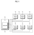
- FIG. 1 illustrates a configuration of a multi-display system 120 according to an exemplary embodiment.
- a display device is exemplarily described to be embodied by a monitor
- a multi-monitor system is exemplarily described to be embodied by six monitors connected to a single computer.
- the computer (PC) 100 outputs a video signal to each of the display devices 130 to 180 depending on a user manipulation to display a video.
- a video signal is output through a video card 110 or a video adapter provided in the computer 100, and includes R, G and B video signals, a horizontal synchronization signal (H-sync) and a vertical synchronization signal (V-sync).
- the video signal includes a video graphics array (VGA), a digital video interactive (DVI), a high definition multimedia interface (HDMI), etc.
- the video card 110 can employ a dual video card (not shown) supporting a separate video signal to each of the display devices 130 to 180 from a single video card, or an independent video card separately supporting each of the display devices 130 to 180 may be mounted.
- FIG. 2 illustrates a configuration of the first display device 130 of the multi-display system 120 according to an exemplary embodiment.
- first display device 130 and the second display device 140 among the first to sixth display devices 130 to 180 are illustrated in FIG. 2 , and the configuration and the operating principle of the second to sixth display devices 150 to 180 may be substantially the same as the first display device 130 unless specified otherwise.
- the first display device 130 includes a signal receiving unit 200, a signal processing unit 210, a display unit 220, a communicating unit 250, a power supplying unit 240 and a control unit 230.
- the signal receiving unit 200 receives a video signal from an external source. Also, although not shown, the signal receiving unit 200 may be configured to receive an audio signal for an audio output, a data signal for a data information output, etc. The video signal, the audio signal and the data signal may be received together through a single signal.
- the signal processing unit 210 performs signal processing so that video can be displayed by the display unit 220 with respect to a received video signal.
- the video processing performed by the signal processing unit 210 may include decoding, image enhancing, scaling, etc.
- the signal processing unit 210 may perform processing with respect to a received audio signal and/or a received data signal.
- the display unit 220 displays video based on a video signal processed by the signal processing unit 210.
- the display unit 220 may be a liquid crystal display (LCD).
- the display unit 220 may include an LCD panel, a panel driving unit, a backlight, etc.
- the display unit 220 may display data information included in a data signal processed by the signal processing unit 210.
- the communicating unit 250 performs communication with the other display devices 140 to 180.
- the communicating unit 250 performs communication under the control of the control unit 230, and may transmit information to the other display devices 140 to 180 or receive information from the other display devices 140 to 180.
- the communicating unit 250 may utilize a general-purpose communication standard, such as a recommended standard (RS)-232, an RS-485, etc.
- RS recommended standard
- the power supplying unit 240 supplies driving power to an element such as the signal receiving unit 200, etc.
- the power supplying unit 240 receives alternating current (AC) power which is a use power, and converts this into electric power of a level necessary for operation of each element to supply power to the corresponding element.
- AC alternating current
- FIG. 2 a path of power supplied to the signal processing unit 210 and the display unit 220 from the power supplying unit 240 is omitted for clarity of the description.
- control unit 230 controls the signal processing unit 210 so that the input video signal can be displayed. Also, the control unit 230 generally controls each element. Also, the control unit 230 may control the power supplying unit 240 to suspend the supply of power with respect to each element in a power saving mode. Also, the control unit 230 may inform other display devices about whether a video signal is input.
- the computer 100 and the video card 110 refer to FIG. 1 . Also, in the following explanation, although the configuration of the second display device 140 is not shown, 'a' is added to a reference numeral of the second display device 140 which is a same element as that of the first display device 130.
- the signal receiving unit 200 of the first display device 130 and the signal receiving unit 200a of the second display device 140 receive a video signal
- the power supplying unit 240 of the first display device 130 and the power supplying unit 240a of the second display device 140 supply all elements of the first display device and the second display device 140 including the signal receiving unit 200 of the first display device 130 and the signal receiving unit 200a of the second display device 140 with electric power.
- the control unit 230 of the first display device 130 and the control unit 230a of the second display device 140 determine that no video signal is output from the video card 110 of the computer 100, and cause the first display device 130 and the second display device 140 to enter a power saving mode.
- the power saving mode refers to the case that a horizontal synchronization signal and a vertical synchronization signal fail to be detected in the signal receiving unit 200 of the first display device 130 and the signal receiving unit 200a of the second display device 140.
- control unit 230 of the first display device 130 outputs to the second display device 140 a control signal informing the second display device 140 that no video signal is input.
- the control unit 230a of the second display device 140 enters the power saving mode if the control signal received from the first display device indicates that no video signal is input.
- the first display device 130 and the second display device 140 If the first display device 130 and the second display device 140 enter the power saving mode, the first display device 130 and the second display device 140 suspend supplying power except to the control unit 230 of the first display device 130 and the control unit 230a of the second display device 140 and a specified element.
- the control unit 230 of the first display device 130 controls the power supplying unit 240 to block electric power supplied to each element.
- the signal receiving unit 200 monitors whether a video signal is output from the video card 110 of the computer 100, the electric power is supplied thereto in the power saving mode.
- the control unit 230a controls the power supplying unit 240a to block electric power supplied to each element.
- the second display device 140 does not monitor a video signal output from the video card 110 of the computer 100. That is, in the case of the multi-display system according to an exemplary embodiment, in the power saving mode, monitoring with respect to a video signal output from the video card 110 of the computer 100 is performed only in the first display device 130. Accordingly, the power supplied to the signal receiving unit 200a of the second display device 140 is blocked.
- the signal receiving unit 200 of the first display device 130 transmits the received video signal to the control unit 230.
- the control unit 230 determines whether a horizontal synchronization signal and a vertical synchronization signal of the video signal are received, and then controls the power supplying unit 240 so that electric power can be supplied to each element so that each element enters the normal mode if the horizontal synchronization signal and the vertical synchronization signal are received.
- the signal receiving unit 200 may determine whether a horizontal synchronization signal and a vertical synchronization signal are input during the process of monitoring whether a video signal is input, and transmit a signal informing the control unit 230 to enter the normal mode if the horizontal and vertical synchronization signals are determined to be input.
- the control unit 230 of the first display device 130 outputs a control signal informing the control unit 230a of the second display device 140 that the video signal is output from the video card 110 of the computer 100 so that the second display device 140 can enter the normal mode.
- control unit 230a of the second display device 140 receives the control signal from the control unit 230 of the first display device 130, the control unit 230a controls the power supplying unit 240a to supply electric power to each element. If electric power is supplied to the signal receiving unit 200a of the second display device 140, the signal receiving unit 200a transmits the video signal output from the video card 110 of the computer 100 to the signal processing unit 210a, and the control unit 230a causes the transmitted video signal to be displayed.
- the second display device 140 may transmit the control signal to the third display device 150.
- the control signal may be transmitted to each of the display devices 140 to 180.
- the first display device 130 may respectively transmit the control signal to the other display devices 140 to 180.
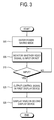
- FIG. 3 is a flowchart illustrating an operation of the multi-display system 120 according to an exemplary embodiment.
- the first display device 130 monitors whether a video signal is input in the first display device 130. If a video signal is not input during a predetermined time, the first display device 130 outputs a control signal which indicates that a video signal is not input. In response to the control signal, each of the display devices 130 to 180 enters a power saving mode (300).
- the first display device 130 monitors whether a video signal is input (305). If a horizontal synchronization signal and a vertical synchronization signal of the video signal are input (YES of 310), the first display device 130 outputs a control signal to the second display device 140 (320), and video is displayed based on the input video signal. If the second display device 140 receives the control signal, the second display device 140 receives a video signal, and displays a video based on the received video signal (330).
- FIG. 4 is a flowchart illustrating an operation of the first display device 130 configuring the multi-display system 120 according to an exemplary embodiment.
- the control unit 230 If a video signal is not input during a predetermined time, the control unit 230 outputs a control signal which indicates that a video signal was not input. Also, the control unit 230 enters a power saving mode (400), and blocks supply of power to each element except the signal receiving unit 200. Then, the signal receiving unit 200 monitors whether a video signal is input (405). If a vertical synchronization signal and a horizontal synchronization signal of the video signal are input (YES of 410), the control unit 230 outputs a control signal to each of the display devices 140 to 180 or only to the second display device 140 (420), and enters the normal mode to display a video based on the received video signal.
- FIG. 5 is a flowchart illustrating an operation of the second display device 140 of the multi-display system 120 according to an exemplary embodiment.
- the control unit 230a If the first display device 130 outputs a control signal indicating that a video signal has not been input, the control unit 230a enters the power saving mode (500), and blocks supply of power to each element.
- the control unit 230a monitors whether a control signal is output from the first display device 130 (505). If a control signal is input (YES of 510), the control unit 230a enters a normal mode, and displays a video based on a received video signal (520).
- power consumption caused by operating in a normal mode when it is determined that a video signal is input as a result of noise, etc. although a video signal is not input, can be reduced.
Landscapes
- Engineering & Computer Science (AREA)
- Theoretical Computer Science (AREA)
- Computer Graphics (AREA)
- Human Computer Interaction (AREA)
- Physics & Mathematics (AREA)
- General Engineering & Computer Science (AREA)
- General Physics & Mathematics (AREA)
- Controls And Circuits For Display Device (AREA)
Applications Claiming Priority (1)
| Application Number | Priority Date | Filing Date | Title |
|---|---|---|---|
| KR1020090106724A KR20110049948A (ko) | 2009-11-06 | 2009-11-06 | 다중 디스플레이 시스템, 디스플레이장치 및 그 구동 방법 |
Publications (1)
| Publication Number | Publication Date |
|---|---|
| EP2336876A1 true EP2336876A1 (fr) | 2011-06-22 |
Family
ID=43513871
Family Applications (1)
| Application Number | Title | Priority Date | Filing Date |
|---|---|---|---|
| EP10164394A Withdrawn EP2336876A1 (fr) | 2009-11-06 | 2010-05-28 | Système d'affichage multiple, dispositif d'affichage et son procédé de commande |
Country Status (3)
| Country | Link |
|---|---|
| US (1) | US20110109608A1 (fr) |
| EP (1) | EP2336876A1 (fr) |
| KR (1) | KR20110049948A (fr) |
Families Citing this family (6)
| Publication number | Priority date | Publication date | Assignee | Title |
|---|---|---|---|---|
| KR101622635B1 (ko) * | 2010-02-12 | 2016-05-20 | 삼성전자주식회사 | 3개의 표시부를 가지는 단말기의 데이터 운용 방법 및 이를 지원하는 단말기 |
| JP2012198348A (ja) * | 2011-03-18 | 2012-10-18 | Fujitsu Ltd | 表示制御プログラム及び方法、並びにコンピュータ |
| US8806235B2 (en) * | 2011-06-14 | 2014-08-12 | International Business Machines Corporation | Display management for multi-screen computing environments |
| KR20140091356A (ko) * | 2013-01-11 | 2014-07-21 | 삼성전자주식회사 | 디스플레이장치, 단말기 및 디스플레이장치의 영상제공방법 |
| KR102500291B1 (ko) * | 2016-09-05 | 2023-02-16 | 삼성전자주식회사 | 통신 인터페이스 장치 및 디스플레이 장치 |
| KR102393933B1 (ko) | 2018-08-30 | 2022-05-04 | 삼성전자주식회사 | 디스플레이 장치 및 그 제어 방법 |
Citations (6)
| Publication number | Priority date | Publication date | Assignee | Title |
|---|---|---|---|---|
| US20010050659A1 (en) * | 2000-06-12 | 2001-12-13 | Yuji Sato | Image display system and display device |
| US6348902B1 (en) * | 1997-04-16 | 2002-02-19 | Samsung Electronics Co., Ltd. | Display device having pass-through function for picture signal |
| US20020067318A1 (en) * | 1997-07-14 | 2002-06-06 | Eiichi Matsuzaki | Display control system and its control method, switching device, connection device, peripheral device, peripheral device system, and their control method, and computer readable memory |
| KR20050069743A (ko) * | 2003-12-31 | 2005-07-05 | 엘지전자 주식회사 | 절전 기능을 갖는 다중 모니터 시스템 및 그 제어 방법 |
| JP2008139772A (ja) * | 2006-12-05 | 2008-06-19 | Nanao Corp | 表示システムおよびディスプレイ装置 |
| EP1947635A1 (fr) * | 2005-10-14 | 2008-07-23 | Matsushita Electric Industrial Co., Ltd. | Dispositif de pilotage d´affichage |
-
2009
- 2009-11-06 KR KR1020090106724A patent/KR20110049948A/ko not_active Ceased
-
2010
- 2010-05-14 US US12/780,574 patent/US20110109608A1/en not_active Abandoned
- 2010-05-28 EP EP10164394A patent/EP2336876A1/fr not_active Withdrawn
Patent Citations (6)
| Publication number | Priority date | Publication date | Assignee | Title |
|---|---|---|---|---|
| US6348902B1 (en) * | 1997-04-16 | 2002-02-19 | Samsung Electronics Co., Ltd. | Display device having pass-through function for picture signal |
| US20020067318A1 (en) * | 1997-07-14 | 2002-06-06 | Eiichi Matsuzaki | Display control system and its control method, switching device, connection device, peripheral device, peripheral device system, and their control method, and computer readable memory |
| US20010050659A1 (en) * | 2000-06-12 | 2001-12-13 | Yuji Sato | Image display system and display device |
| KR20050069743A (ko) * | 2003-12-31 | 2005-07-05 | 엘지전자 주식회사 | 절전 기능을 갖는 다중 모니터 시스템 및 그 제어 방법 |
| EP1947635A1 (fr) * | 2005-10-14 | 2008-07-23 | Matsushita Electric Industrial Co., Ltd. | Dispositif de pilotage d´affichage |
| JP2008139772A (ja) * | 2006-12-05 | 2008-06-19 | Nanao Corp | 表示システムおよびディスプレイ装置 |
Also Published As
| Publication number | Publication date |
|---|---|
| US20110109608A1 (en) | 2011-05-12 |
| KR20110049948A (ko) | 2011-05-13 |
Similar Documents
| Publication | Publication Date | Title |
|---|---|---|
| EP2336876A1 (fr) | Système d'affichage multiple, dispositif d'affichage et son procédé de commande | |
| KR100418703B1 (ko) | 디스플레이장치 및 그 제어방법 | |
| US20030107566A1 (en) | Display apparatus and method of supplying power to USB device thereof | |
| KR101463471B1 (ko) | 외부장치의 상태를 알리는 디스플레이장치 및 그 방법 | |
| US7812836B2 (en) | Display apparatus and power control method thereof | |
| EP2544173A2 (fr) | Appareil d'affichage d'images et procédé de commande de l'appareil d'affichage d'images | |
| US8681094B2 (en) | Display apparatus and method for controlling display apparatus | |
| EP1967948A2 (fr) | Appareil d'affichage d'image pour contrôler un dispositif de transmission de données externes utilisant un connecteur USB et son procédé | |
| EP2549360A1 (fr) | Dispositif d'affichage, dispositif hôte, système d'affichage, procédés de contrôle du dispositif d'affichage, dispositif hôte et système d'affichage | |
| US20100079432A1 (en) | Display apparatus and method thereof | |
| CN101261824A (zh) | 用于显示通过多种连接器输入的视频的显示装置 | |
| US20100245210A1 (en) | Circuit for detecting an external display device adapted to notebook computer and detecting method thereof | |
| EP2221795A1 (fr) | Interface vidéo numérique supportant le signal de prise double ou le signal de prise simple | |
| KR20120002838A (ko) | 컴퓨터시스템 및 그 제어방법 | |
| KR20090058359A (ko) | 액정 판넬 디스플레이 장치 및 방법 | |
| KR100702241B1 (ko) | 디스플레이장치 및 그 제어방법 | |
| JP4291663B2 (ja) | 液晶表示装置 | |
| KR100370047B1 (ko) | 모니터의 디스플레이 데이터 처리장치 | |
| KR20060004410A (ko) | 디스플레이 시스템 및 그 제어방법 | |
| KR100598415B1 (ko) | 디스플레이장치 및 그 제어방법 | |
| KR100704667B1 (ko) | 디스플레이장치 및 그 전원제어방법 | |
| US20090115752A1 (en) | Display apparatus and method | |
| KR20160150213A (ko) | 디스플레이 패널, 디스플레이 패널을 포함하는 디스플레이 장치 | |
| JP2001337309A (ja) | 液晶ディスプレイ装置 | |
| KR101178124B1 (ko) | 영상표시장치의 디스플레이 대기 전력 감소 장치 및 방법 |
Legal Events
| Date | Code | Title | Description |
|---|---|---|---|
| PUAI | Public reference made under article 153(3) epc to a published international application that has entered the european phase |
Free format text: ORIGINAL CODE: 0009012 |
|
| AK | Designated contracting states |
Kind code of ref document: A1 Designated state(s): AL AT BE BG CH CY CZ DE DK EE ES FI FR GB GR HR HU IE IS IT LI LT LU LV MC MK MT NL NO PL PT RO SE SI SK SM TR |
|
| AX | Request for extension of the european patent |
Extension state: BA ME RS |
|
| 17P | Request for examination filed |
Effective date: 20111208 |
|
| RAP1 | Party data changed (applicant data changed or rights of an application transferred) |
Owner name: SAMSUNG ELECTRONICS CO., LTD. |
|
| 17Q | First examination report despatched |
Effective date: 20151126 |
|
| STAA | Information on the status of an ep patent application or granted ep patent |
Free format text: STATUS: THE APPLICATION IS DEEMED TO BE WITHDRAWN |
|
| 18D | Application deemed to be withdrawn |
Effective date: 20160407 |