EP2336920A2 - Procédé pour la génération semi-automatique d'une simulation se fondant sur la exploration iterative - Google Patents
Procédé pour la génération semi-automatique d'une simulation se fondant sur la exploration iterative Download PDFInfo
- Publication number
- EP2336920A2 EP2336920A2 EP10184769A EP10184769A EP2336920A2 EP 2336920 A2 EP2336920 A2 EP 2336920A2 EP 10184769 A EP10184769 A EP 10184769A EP 10184769 A EP10184769 A EP 10184769A EP 2336920 A2 EP2336920 A2 EP 2336920A2
- Authority
- EP
- European Patent Office
- Prior art keywords
- memory
- analog
- simulation
- partitions
- processors
- Prior art date
- Legal status (The legal status is an assumption and is not a legal conclusion. Google has not performed a legal analysis and makes no representation as to the accuracy of the status listed.)
- Withdrawn
Links
Images








Classifications
-
- G—PHYSICS
- G06—COMPUTING OR CALCULATING; COUNTING
- G06F—ELECTRIC DIGITAL DATA PROCESSING
- G06F30/00—Computer-aided design [CAD]
- G06F30/30—Circuit design
- G06F30/36—Circuit design at the analogue level
- G06F30/367—Design verification, e.g. using simulation, simulation program with integrated circuit emphasis [SPICE], direct methods or relaxation methods
Definitions
- Simulating the behavior of a proposed or actual design reduces the effort required to realize and maintain the design.
- designers may compare the desired and predicted behavior of a design using simulation. After realizing the system into dedicated hardware and software and throughout the design's lifecycle, simulation facilitates understanding of unexpected design behaviors and subsequent evaluation of proposed design modifications.
- Design behavior may be simulated at many different levels of detail.
- Abstract models of design behavior with comparatively little detail generally simulate comparatively fast.
- the predicted and actual design behavior generally converge while the rate of simulated and actual design behavior diverge. Equivalently, simulation generally becomes increasingly slower as the accuracy of detail increases.
- Designs are not only slower, they impose a significant effort on the design team in order to accurately "model” a system's behavior so that it can be simulated.
- Designers or model extraction tools typically represent a design's behavior using one or more modeling languages.
- Structure modeling languages such as SPICE, represent a system in terms of flat or hierarchically connected components.
- a structural modeling language represents terminal components using behavioral models described using a conventional programming language, such as C or Fortran, or a behavioral modeling language, such as VHDL or Verilog (digital), VHDL-AMS or Verilog-AMS (mixed signal).
- Radio frequency and microwave (RF/MW) languages perhaps augmenting a base language such as VHDL-AMS or Verilog-AMS, typically add modeling language features such as means for modeling distributed (rather than lumped) parameter components, means for component modeling in the frequency domain (rather than just the time domain) and means of effectively modeling noise and parasitic interactions.
- a conventional programming language or behavioral modeling language represents system behavior using terminals, branches and equations representing an implicit relationship between quantities (the implicit relationship embodied as Kirchoff's laws for the analog and mixed signal or Maxwell's and continuity equations for full-wave modeling).
- Terminals sometimes known as “nodes" represent the connection point between two or more branches.
- the network formed by terminals connected by branches may be represented as one or more disconnected graphs embodying terminals and branches with associated across quantities, such as voltage, and through quantities or contributions, such as current.
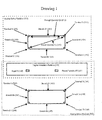
- Figure 1 represents the relationship between terminals (such as 152, 154, 156, 159, 162, 164, 166 and 168), branches (such as 153, 155, 157, 158, 163, 165, 167, 169) and implied quantities such as through quantity Q2 (172) or across quantity Q1 (151).
- terminals such as 152, 154, 156, 159, 162, 164, 166 and 168
- branches such as 153, 155, 157, 158, 163, 165, 167, 169
- implied quantities such as through quantity Q2 (172) or across quantity Q1 (151).
- Well known techniques provide for partitioning analog models which do not share terminals, branches or quantities, such as the partitions marked 150 and 169 in Figure 1 . Recognizing such partitions early in the compilation process will become useful in the present invention; means for recognizing such disconnected partitions are well-known.
- analog modeling languages enable declaration and reference to continuously valued state variable quantities representing physical properties, such as voltage or current, and quantities implicitly or explicitly derived from such quantities.
- Mixed signal modeling languages enable reference to digital objects such as signals, shared variables, registers and comparable, discretely-valued objects. Such digital objects may be contained in a distinct digital partition, such as 170 in Figure 1 and referenced from both the digital partition and zero or more analog partitions, such as 150 or 169 in Figure 1 .
- Source code references in a model using a mixed signal language typically take the form of one or more constraints relating left and right hand side expressions at a specific instant in time to within an implicit or explicit tolerance.
- Sets of such equations referencing common quantities and digital objects are commonly known as systems of equations, characteristic equations, simultaneous equations or constraint equations. Without loss of generality we will refer to these as equation systems in the following.
- the behavior of an analog partition may be modeled in the time domain (primary independent variable is time) or in the frequency domain (primary independent variable is frequency).
- time domain primary independent variable is time
- frequency domain primary independent variable is frequency
- the behavior of a voltage-controlled oscillator may be most conveniently modeled in the time domain whereas the transfer function of a filter or amplifier may be most easily and compactly captured in the frequency domain.
- the prior art effectively addresses many aspects of modeling in either domain, however prior art does not effectively address tight integration of digital inputs, analog time domain behavior and analog frequency domain behavior into a common analog partition or partitions.
- the left or right hand side of inequalities within an equation system may result from evaluation of substantially complex expressions involving constructs such as procedural control flow, conditional statements and analog events. Without loss of generality, such notations may be compiled into a variety of equivalent forms corresponding to sets of equation systems where an expression and evolving state may be evaluated to identify an active equation system at any instant in time from among the set of equation systems potentially modeling an analog, mixed-signal or full-wave partition's behavior.
- Each such equation includes one or more language-defined means for evaluating an identifiable value or range of values on the left and right side of each inequality within the equation system. Such values are generally known to have either scalar or composite type.
- both quantity values and the equation system which is active within a set of equations systems describing an analog partition may change.
- the change may be implicit in the set of equations and therefore must be detected during simulation or may be explicitly denoted, as with a "break" statement denoting an expected discontinuity.
- the model of a digital to analog converter commonly has such instantaneous discontinuities explicitly corresponding to changes in the digital value which is to be converted by the design into an analog value.
- VHDL-AMS Behavioral, mixed-signal modeling languages, such as VHDL-AMS and Verilog-AMS, interleave or alternate simulation of analog and digital design partitions, increasing the opportunity for discontinuities between quantity values at two successive points in time.
- Digital values may be referenced in an analog partition by direct reference (such as VHDL-AMS) or by explicit interface mechanisms (such as Verilog-AMS).
- Analog quantities may be referenced in a digital partition directly, via threshold language mechanisms (such as VHDL-AMS) or via more complex interface mechanisms (such as Verilog-AMS).
- VHDL VHDL-AMS
- Verilog Verilog-AMS
- VHDL already provides a descriptive language mechanism by which physical phenomena such digital phenomena as tri-state and open-collector/emitter interconnect technology may be semi-transparently introduced into simulation while being ignored during uses such as the synthesis of hardware. The mechanisms are known as "resolution" functions.
- VHDL resolution functions for digital interconnects may be associated with an existing type to form a new, resolved, subtype.
- the new, resolved subtype may then be used to define a "resolved signal".
- the signal may appear on the left hand side (assignment target) of digital equations.
- the resolution function originally associated with the signals subtype conceptually executes. Execution of this resolution function takes specific assigned values to the signal as inputs and returns a resolved value representing the tri-state, open-collector or other resolution behavior.
- the array of inputs and resolution function return value may either be an array of scalar types resolved to a scalar type or may hierarchically resolve a composite type consisting of zero or more composite scalar types.
- the number of distinct inputs to a resolution function may not be known until after a system begins simulation. Some inputs to a resolution function may not actually be assigned at all or may not be assigned during a specific period of time. Conversely, during simulation additional drivers may be added which assign to a signal. Addition may occur as a result of executing the mixed signal design representation or more commonly through execution of a programming language fragment introduced through a programming language interface (PLI) to the system representation.
- PLI programming language interface
- code generated to perform simulation must accommodate the worst case resolution context and thus is less efficient than if code was generated for the actual number of active inputs to the resolution functions.
- Commonly resolved signals are driven by an expression's left hand side (or functionally equivalent left hand sides within a process) via the process equivalent's driver. Often the resolution function call for such signals may be eliminated or significantly simplified, for example if there is only one driver, thus improving performance.
- Non-linear systems include terms within their system of equations which depend on quantities or expressions involving quantities taken to powers other than one.
- a non-linear component model may depend on the square of the voltage across a pair of terminals.
- Systems comprising non-linear components are computationally more complex to simulate and thus slower than linear system simulations.
- Each partition may refer to digital objects (such as signals or shared variables), analog objects (such as quantities or terminals) or values derived from these objects.
- analog partitions and full wave partitions set the value of analog objects.
- Digital partitions set the value of digital objects.
- the set of all objects (analog and digital) referenced by a partition forms an operating space, such as the example shown in Figure 2 .
- the domain of values which a given object may assume (based on its subtype) forms an axis of the operating space (such as 50, 51 or 52 in Figure 2 ).
- a partition's operating space has one dimension for each scalar element of each object.
- the three dimensions shown in the example of Figure 2 correspond to two analog quantities A (50) and B (51) and open digital object, perhaps a signal (52).
- Each dimension of the partition's operating space may be divided. When combined with divisions of other dimensions, this forms a subspace of the operating space or an operating context (by which it will be subsequently known). Operating points contained within a single context have closely related values.
- the observed object values can be contained within an operating context.
- the non-linear system of characteristic equations can be approximated by a linear model.
- Techniques for deriving such approximations known as "linearization" techniques, are well-known in the literature.
- the analog partition is operating in a single, identifiable operating context with a corresponding linearization of an equation system (currently) representing the analog partition's behavioral model.
- a sparse matrix implementation takes advantage of many zero-valued "conductance" matrix values to achieve substantially more compact representations than the square of the array dimensions would imply.
- Prior art teaches a variety of transformations on the sparse matrix representations which reduce the magnitude of off-diagonal elements (toward zero) and thus accelerate simulation. However for designs of practical interest, the off-diagonal elements of the conductance matrix are seldom all zero.
- Prior art also teaches techniques by which the current and voltage relationships within an operating context may be approximated by one or more tables. Such tables are constructed prior to simulation, then interpreted by machine instructions common to more than one operating context. Significantly, the innovations taught here allow optimization of the machine instruction sequences for a specific operating context.
- Electronically re-configurable logic devices such as field programmable gate arrays (FPGAs) are often used to accelerate simulation designs at digital levels of abstraction, either in the form of emulators or simulation accelerators.
- FPGAs field programmable gate arrays
- the parallelism available inside of such devices results in substantial speedups relative sequential simulation execution through the execution pipeline of a single processor or a modest number of processors within a multiprocessor.
- Prior art does not teach any efficient means for utilizing the parallelism of electronically re-configurable logic devices for the simulation of analog, mixed-signal or full-wave abstraction levels.
- At least one electronically re-configurable logic device has been fabricated with electronically re-configurable analog modules, such as amplifiers and filters. From the standpoint of simulation use, this device substantially lacks accuracy, noise-immunity, dynamic range, capacity and flexibility required for effective simulation of analog, mixed-signal or full-wave abstractions. Fundamentally it represents quantity values as actual analog values rather than as their sampled digital equivalents.
- FPGA devices For ease of reading following current common use, the following will refer to FPGA devices although the references are understood to generalize to the broader class of electronically re-configurable logic devices (no matter what their architecture or market positioning).
- the references to FPGA are understood to embrace electronically re-configurable interconnects, memory arrays and various configurations of logic cells from fully programmable gates to large logic blocks where only selective interconnect and functionality aspects are electronically programmable.
- Prior art either maps digital signals directly to pins and traces connecting the pins of various devices or time-multiplexes several signals on the same pins.
- the value of a quantity at one time step numerically differs relatively little from the value at the next time step. This is especially true for analog, mixed-signal and full-wave quantities, however the same observation can be made to a lesser degree in the context of digital values.
- Quantity values in the prior art rely almost exclusively on floating point representations (consisting of a mantissa, implied base and exponent). Since general purpose processors efficiently execute a small number of numeric representations (corresponding to those defined into the processor's instruction set and realization), use of floating point representations are the easiest way to gain increased range.
- use of floating point representations has several significant drawbacks, especially in the context of FPGA implementations designed for maximum performance. Even serial implementations of floating point operators are significantly larger and more complex than integer representations, putting FPGA logic at a premium. Normalization and related floating point operations inherently require more time to execute than equivalent integer implementations. Numerical precision is much more difficult to formulate than for integer operations since precision changes as floating point values deviate from a central value, typically 1.0.
- the flexibility of FPGA logic enables fabrication of almost arbitrary precision integer arithmetic logic, providing alternatives to floating point representation in order to increase usable numerical dynamic range.
- over-design must come at the expense of both decreased functionality and increased power consumption. Over-design throughout a design generally results in a significant decrease to both the design's user functionality and power, yet it only delays the potential for failure due to overflow, underflow or loss of precision.
- Design typically embody existing intellectual property, such as cell libraries or even entire microprocessors. For business reasons, owners of this intellectual property want to export models representing the behavior of these components while restricting the level of implementation or realization detail exposed.
- Previously such models either used code compiled into assembly language, such as the Synopsys Smart Model or inserted actual devices into the simulation, as in the Logic Modeling Real Chip product.
- Compiling component models into an assembly code format is only useful when executing simulation on a general purpose processor for which a compiled representation exists. Such models must be decrypted before simulation begins, leading to the potential for disassembly of the model's assembly code representation and thus compromise of the owner's intellectual property.
- assembly code model prior art describes how to insert actual devices into a simulation.
- Accurate analog, mixed-signal and full-wave models are essential to the synthesis of new analog designs, the retro-fit of existing designs and the modeling of complex designs with one or more missing component models.
- the prior art offers techniques for manually fitting a model around characterization of operating specifications, however both the gathering of such specifications and the effective fitting of data to achieve a new model is a slow, manual process in the prior art.
- the cost and time expenditure implicit in such a manual process are a significant disadvantage of the prior art.
- Effective comparison techniques are a significant intermediate step in enabling the effective, semiautomatic generation of analog, mixed-signal and full wave component models.
- Such comparison provides an essential calibration in the process of semiautomatically developing a new analog, mixed-signal or full-wave model corresponding to an existing simulation or actual device.
- the most powerful prior art available to compare analog, mixed-signal or full-wave models relies on exhaustive simulation of a reference and comparison model under a wide variety of operating conditions.
- Comparison of analog, mixed-signal or full-wave models via exhaustive simulation is both time consuming and ultimately fragile. Since it is not possible to simulate all operating modes in a bounded time, the risk of missing a key difference in the behavior of reference and comparison model must remain. Even the time required to conduct enough simulation to approach a given confidence level increases beyond practical limits as the complexity of devices being compared increases.
- Textual comparisons of reference and comparison models are especially fragile. Models with closely related lexical and syntactic constructs may exhibit radically different behaviors. For example, a function which approaches positive infinity from one side of a critical value and negative infinity on the other side of the critical value will be extremely sensitive to behavior around this critical value. Conversely a trignometric function and its Taylor expansion can be lexically and syntactically very different, yet yield acceptably equivalent values over an interesting operating range. Therefore prior art based on textual comparison, such as the Common available textual differencing utilities are of little practical value in the problem of analog, mixed-signal or full-wave model comparison.
- a code fragment for each possible Operating Context may be compiled prior to simulation. Since the number of possible Operating Contexts can be large and comparatively few Operating Contexts will actually be encountered during most simulations, a further method for incrementally compiling analog solver code fragments on demand is taught. Once compiled, such code fragments may be retained for subsequent re-use (cached) during the same or subsequent simulation runs.
- Figure 7 illustrates a means of computing the Operating Context from the current values of objects referenced from the Analog Partition. From each value, the range of values needed to distinguish an Operating Context (see Figure 2 ) in which referenced objects have a sufficiently linear relationship are extracted and form a Key (309). The Key (309) may then be used to identify a existing Context-Specific Analog Solver or create an appropriate Context-Specific Analog Solver from the Elaborated Representation (see Figure 6 , 4 ) via the Incremental Compiler / Assembler / Loader (see Figure 6 , 5 ).
- Context-Specific Analog Solvers embody numerical solver algorithms known from the prior art including linearization of Algebraic Equations, Ordinary Differential Equations and Partial Differential Equations about an operating point within the Operating Context, numerical algorithms to update Analog Object Values based on direct or iterative solution (such as Newton/Raphson iteration) and numerical algorithms to integrate or differentiate Analog Objects.
- Context-Specific Analog Solvers may be compiled into General Purpose Processor Instructions (such as 508 and 509) which may direct reference to Object Values via one of the many instruction set effective addressing modes well-known to assembly language programmers and computer designers.
- Breakpoints include failure to approach tolerances during successive simulation cycles (failure to converge), failure to converge after a specified number of analog solver cycles at the same time point, reaching a specific time point, attaining specific object values or matching a specific data access pattern.
- Other sources of breakpoints are commonly known from the simulator or program debugging literature and are known to those skilled in the art of programming language interface or debugger design.
- Figure 6 illustrates the set of software components typically employed to implement this method.
- a Source Code Analyzer (1) compiles textual or graphical models of a design to a Post-Analysis Representation (2).
- a Static Elaborator and Inliner (3) compiles the Post-Analysis Representation (2) into an Elaborated Representation (4).
- An Incremental Compiler / Assembler / Loader (5) then generates General Purpose Processor Instructions (508 and 509) used to implement Context-Specific Analog Solvers (7), Executable Digital Partitions (8) and Embedded Scheduling Executables (1000 of Figure 24) needed to schedule the execution of Context-Specific Analog Solvers (7) and Executable Digital Partitions (8).
- An innovative method is taught for generation of either structural or behavioral mixed-signal models using iterative probing of an existing model embedded in a simulation or an existing device embedded in a test set suitable for applying stimuli and retrieving the response.
- the technique is useful in the context of analog and mixed-signal simulation as a means to generate suitable textual models from other sources (avoiding the need to cosimulate with other simulators or insert actual devices into a running simulation), as a means of generating more abstract (and thus faster models) as shown in Figure 9 (453) or for the semi-automatic synthesis of analog components matching a behavioral specification.
- FIG 19 shows the major steps required to practice the method.
- a Template Library (868) contains an incrementally extended collection of parameterized component templates in an intermediate format (such as FTL Systems' AIRE/CE Internal Intermediate Representation).
- a Template Selection Step (850), Equation Fitting (852) and Parameter Fitting Step (854) select and refine templates until Model Source Code Generation (856) produces a Textual Representation as Source Code or Intermediate Format suitable for direct compilation into a simulation.
- Test Model Generation and Analysis component sets up an actual device or simulation for a particular Operating Context, then converse a response into a parametric equation form suitable for Template Selection, Equation Fitting and Parameter Fitting.
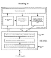
- FIG. 20 provides additional detail on the Template Library (868) and Template Selection (852).
- the Template Selection (850) consists of three steps:
- Template match produces an incrementally refined match to Template Selection criteria by either generating a template on-the-fly to meet the specification, via the Template Generator (900) or via reference to a previously generated pair of behavioral and structural models.
- Behavioral models use an Equation System to define the behavior (potentially including conditional constructs and discontinuities between Operating Contexts) as well as a structural equivalent.
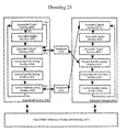
- Figure 22 illustrates the comparison technique.
- Reference and comparison models are analyzed into a Post-Analysis Intermediate Representation (900 and 901), Elaborated and Statically In-lined into a Post- Elaboration Form (902 and 903), then converted into a canonical form suitable for graph matching (904 and 905).
- Comparison methods first attempt to build a correspondence between the two graphs (906). If a correspondence can be made, numerical values assigned to nodes and branch values are compared.
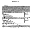
- Icons represent hierarchical structure, objects and equations. Each icon is divided such that portions of the icon may be colored, shaded or otherwise differentiated in appearance. Comparison of the two appearances of each icon provide a visual representation of how closely the reference and comparison structure, objects or equations match by com-paring the appearance of distinct icon regions. The match may be either a time-average or may vary dynamically to reflect the immediate difference in value. Structural icons denote the aggregate value of their component structure, objects and equations.
- terminals denote a point at which contributions from two or more branches converge, such as the lumped parameter terminal (202) at the top of Figure 3 .
- the preferred embodiment allows a technologist to encapsulate a more detailed interconnect model (consisting of quantities and equation systems) as an implementation of the interconnect behavior.
- FIG. 3 shows a comparatively simple expansion from a single terminal to an array of implied terminals. Connections made by the designer to the original terminal (202) may either be associated by default (as with resolution functions) or by explicit reference to elements of the terminal array (such as 202 and 206). Those skilled in the art of hardware description language design will readily generalize from the implied terminal array (204) into a two or three dimensional lattice suitable for finite element implementation of a full-wave equation solver.
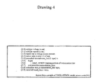
- Figure 4 illustrates the corresponding fragment within an extended VHDL-AMS syntax.
- Lines 210 and 211 declare a very conventional definition of current and voltage.
- Lines 212 and 213 define a comparatively conventional nature and unconstrained array of natures.
- Line 214 defines a procedure (or equivalently this could be a Verilog task) implementing the behavior of a distributed transmission line.
- this procedure may then be used in the formation of a distributed subnature analogous to the association of a function and subtype to implement a digital resolution function.
- the subnature may then serve as the nature of a terminal declaration, as in Line 219.
- Parameters to a distribution function must be a terminal interface declaration of an unconstrained nature followed by zero or more interface declarations used to customize the distribution procedure's behavior for a specific terminal declaration.
- the constant or variable interface declarations may represent a specific dielectric constant, characteristic impedance or even time-varying property such as the local temperature within the system model of a micro-electronic machine. Subsequent signal, shared variable or other terminal declarations may provide for modeling explicit induced noise or parasitic couplings.
- Values may be associated with the distribution function's constant or variable parameters at the point where the nature is associated with a specific terminal declaration.
- distribution function parameters and constraints must be syntactically distinguished.
- One means for distinguishing the distribution function parameters and constraints takes advantage of the need to provide a constraint for each unconstrained dimension of the nature at the point where the nature is associated with a terminal. Therefore the constraints, if any, may appear as a parenthetic list. Distribution parameter associations, if any, may then appear as a subsequent parenthetic list.
- Other means of syntactically denoting constraints and parameter values are possible and are commonly known to language designers.
- Quantities then refer to terminals (and thus instances of distributed natures) to form branch quantities and thus characteristic, simultaneous or constraint equations representing the design's behavior.
- terminals are either scalars or composites ultimately defined in terms of scalars.
- Each scalar nature has an across and through type relative to an explicit or implied reference terminal.
- the reference terminal commonly represents a localized or global "ground”.
- the resolution function's input dimensionality is imposed external to the resolution function by the set of drivers immediately contributing to the resolved signal's value.
- the terminal subnature's distribution function must internally impose a constraint on a specific, unconstrained parameter based on the terminal's immediate modeling requirements chosen by the technologist who created the distribution function. To the system designer using the terminal with a nature having a distribution function, the terminal appears to be a lumped parameter with all the modeling ease of use commonly associated with a lumped parameter model.
- the technologist controls the dynamic degree of distribution, the modeling mechanism and even the parasitic couplings not explicitly denoted by interface associations at the point where the distributed nature was associated with the terminal through definition of the procedure's body.
- This degree of flexibility cleanly and orthogonally separates language design from modeling methodology, facilitating the independent efforts of mixed-signal system designers, technologists and tool developers.
- This de-coupling results in a technology-independent language design with broad applicability and thus an implementation expense spread over many application domains. Therefore it is a useful innovation.
- VHDL's resolution functions are not of direct help. Indeterminate mapping between external signals and resolution function input elements for digital VHDL are one of the major sources of non-deterministic behavior within VHDL. Such non-determinism is generally recognized and somewhat reluctantly accepted as a compromise to achieve higher performance and language simplicity.
- One means of addressing both the digital resolution function parameter association problem and the more immediate need for association with the first parameter of a terminal declaration's distribution procedure is to make the unconstrained array explicit at points which refer to the terminal.
- a terminal with a sub-nature having a distribution procedure could either be referenced with an indeterminate array type, in which case the association would be indeterminate, or via explicit array subscript expressions.
- one end of a transmission line model might refer to terminal subscript zero whereas the opposite end would refer to terminal ' length.
- Other methods for making the association and extensions to language other than VHDL will be obvious to those skilled in the art of language design.
- general purpose processor instructions or configured logic result in a re-invocation of the compiler if the asserted signal, quantity, shared variable or terminal configuration does not actually occur (227). Iteratively the execution traps on the exception (230), potentially re-uses a cached implementation of an instruction sequence or configured logic matching the conditions actually occurring during a simulation and continues execution.
- the technologist may directly or indirectly include several implementations in the procedure representing interconnect functionality. If a quantity or variable rep-resenting frequency is below a threshold, the terminal may remain lumped. If the frequency exceeds the first threshold, the implementation may use a relatively coarse transmission line model. At still higher frequencies the procedure may use a full-wave model implemented using explicit finite element techniques. How-ever it is very important to note that our innovation simply supplies a very flexible and efficient method for a skilled technologist to implement many different kinds of condition-specific interconnect models; our innovation does not embody any specifics of device or interconnect technology and thus is extremely general and flexible. As with resolution functions, the innovation facilitates a decomposition of skill between the overall designer and the interconnect or device technologist.
- FIG. 6 illustrates the overall software components within the preferred embodiment.
- Components 1 through 5 are processor instructions configuring the persistent storage system, memory and instruction cache(s) of a uniprocessor, shared memory multiprocessor or cluster of such processors (software).
- Components 6, 7, 8, and 31 may be implemented in software or electronically re-configurable logic devices (often known as FPGA).
- the Source Code Analyzer (1) is a means of incrementally translating from graphical or textual models of a digital, analog or mixed signal design into a post-analysis representation (2).
- One common example of such an analyzer is FTL Systems' Tauri source code analyzer translating into FTL Systems' AIRE/CE Internal Intermediate Representation (ILR).
- the Post-Analysis Representation (2) supplies representation elements such as literals, identifiers, strings and declarations to both directly to the Incremental Compiler / Assembler / Loader (5) and to the Static Elaborator and Inliner (3).
- the Post-Analysis Representation (2) triggers (11) the Static Elaborator and Inliner (3) which subsets of the Post-Analysis Representation (2) have changed since the start of compilation or the last Design Epoch.
- the Static Elaborator and Inliner (3) then incrementally queries the Post-Analysis Representation (2) to generate or update Elaborated Representations (4) through application of rewriting rules defined by the modeling language(s) in use or by conventional compiler optimizations such as subprogram inlining, loop unrolling, constant propagation and related transformations.
- the Elaborated Representation (4) consists of constructs denoting digital objects, digital partitions, analog objects, analog partitions and full-wave partitions along with back-annotations to the Post-Analysis Representation (2) and eventually textual source code. Back-annotations are used for interactions with the designer such as source level debug, profiling, timing annotation and related functions.
- the Incremental Compiler / Assembler / Loader (5) may begin compilation into an executable form, ultimately resulting in Executable Digital Partitions (8) and/or Executable Analog Partitions (7).
- Compilation cycles by the Incremental Compiler / Assembler / Loader (5) may ultimately be triggered by the Designer (resulting from design changes or interactive debug/profiling) or by the executing digital and/or analog simulation. The latter trigger is an innovative step.
- the Incremental Compiler / Assembler / Loader (5) includes the following compiler functionality:
- Executable Digital Partitions (8), Executable Analog Partitions (9) or full-wave partitions (not shown) either use Embedded Scheduling techniques first taught by the present inventor in 1991 or an innovative generalization of these techniques to multiprocessor and re-configurable logic implementations.
- Embedded Scheduling combines processor instructions and re-configurable logic implementing models of design components with processor instructions and re-configurable logic implementing event transmission and execution scheduling.
- Incremental compilation operations resulting in changes to Executable Digital Partitions (8), Executable Analog Partitions (7) or Executable Full-Wave Partitions (not shown) are often transient.
- Common examples of such changes include breakpoint insertion, callback insertion, optimization of digital resolution function implementations, linearizations of an equation system at an Operating Context and substitution of various interconnect components within an analog partition.
- Processor instruction sequences implement these changes by changing the target of instructions such as jump, conditional jump, branch, conditional branch, call and return or substituting an existing instruction by one of these jump, branch, call or return instructions.
- Re-configurable logic implements these changes by re-configuring one or more logic cells or altering interconnect configurations.
- previous instruction fragments or logic fragments may optionally be retained in a hardware or software cache.
- Digital, analog and full-wave fragments may optionally be cached in separate caches such as the Cached Digital Partition Fragments (31) or the Cached Analog Solve Fragments (6).
- Requests for potentially cached fragments may be routed directly to the compiler, as in paths (23/25), or optionally requests may be routed via the corresponding cache (18/26), flowing on to the compiler in the case of a cache miss (19/28).
- the compiler may in turn supply the incrementally compiled fragment directly to the executable (15/16) for immediate loading or optionally via the cache (20/21 or 29/30).
- Bit fields which define a partition's Operating Context from objects, their subtypes and sub-natures are extracted from the current object values to form a Cache Key (309). Bit fields which define a particular point within an Operating Context are not used in the key formation.
- the resulting key may be used directly for Cache Lookup (310) or indirectly by computing an additional Hash function (311). Due to the large number of bits often involved in a key, some means of lookup acceleration, such as a hash, is often a practical requirement. Lookup then uses both the key (310) and its hash (312) for lookup.
- a wide variety of techniques for computing hash functions and implementing a cache lookup are known to those skilled in the art.
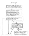
- the analog solver simulation cycle is shown in Figure 8 .
- Conceptually the same sequence of steps occurs when executing using a sequence of instructions or re-configurable logic; the primary differences are in the implementation of Incremental Compilation (354) and Evaluation (352).
- the compiler loads initial values, instructions and re-configurable logic configurations.
- instructions or logic implement a means of Operating Context Determination (as discussed above in the context of Figure 7 ).
- Operating Context Match Logic deter-mines if an existing instruction sequence or logic configuration is already available to implement the partition's behavior in the partition's current operating context.
- the Operating Context Match Logic (351) will produce one of three outcomes: the partition's current instruction sequence or logic configuration is a suit-able implementation of the partition's behavior in the operating context (363 leading to 356), a suitable implementation is available in the cache (364 leading to 357) or a suitable instruction sequence must be compiled (365 leading to 354), loaded into the cache (370 leading to 355) and loaded for execution (371 leading to 358).
- the analog solver executes to identify new values to associated with analog objects.
- the solver updates quantity values, evaluates left and right hand sides of each com-piled equation and compares the difference against the acceptable tolerance defined by the applicable language reference manual (353). If all compiled equations in the analog partition are less than a tolerance away from equality, the Digital Simulation Cycle (359) runs with an implementation comparable to the one shown in Figure 8 , otherwise the updated quantity values lead to a new Operating Context Determination (374 leading to 350) and the analog solver cycle begins again.
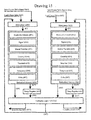
- Figure 9 details the means of Incremental Compilation (used at step 354 in Figure 8 or the equivalent step during the digital simulation cycle (359)).
- Post-Analysis Design Representations (2), changes in a partition's Operating Context (27) and Design Epoches in the Elaborated Representation (4) all result updates maintaining a revised logical view of digital or analog partitions.
- partitions are logical in the sense that compilation may further schedule the partition for execution on multiple processors and/or logic devices or multiple logical partitions may be combined on a single processor or re-configurable logic device using Embedded Scheduling.
- a distinct compilation phase, Pseudo-Static Technology Binding and Scheduling maps logical partitions onto specific processor and/or re-confgurable logic devices.
- the technology binding and scheduling step estimates the processor resources (clock cycles and number of processors) and logic resources (number of logic blocks and interconnects) required to implement the logical partition. Then using well-known techniques for static scheduling, this step determines which implementations and bindings to specific execution hardware are most efficient in reducing the partition's execution time. Subsequent compilation steps use this schedule to choose a subsequent implementation technology (474, 475, 476, 477 and 478).
- Model abstractors which can successfully implement an abstraction generate a revised resource estimate (474) which may in turn impact a more generate technology binding and scheduling (475, 476, 477).
- Model Abstractors replace operators, data types and components within a design with a simpler form expected to have observably equivalent behavior based on expected use. If use expectations differ from actual use during simulation, the equivalent model must be transparently replaced (via re-compilation) and the more complex implementation restored. For example, adder logic using a multi-valued logic system may be abstracted into a processor's add instruction using a two-value logic system based on the (validated) expectation that only zero and one values occur and that the adder logic is correct. A comparable analog model abstractor might replace an amplifier circuit with an equivalent behavioral model.
- Digital (454), analog (456) and full-wave (455) code generators create an intermediate representation which is exported to a sequence of back-end code generation steps for an instruction set sequence (483, 484, 495), re-configurable logic (485, 486, 487) or both.
- Generators may emit an intermediate format such as C, EDIF or XDL suitable for an external compilation or synthesis step. Such external steps attain an equivalent end result, generally with substantially higher compilation latency.
- the incremental assembly step consists of an Incremental Assemblers (457), Incremental Linker (458) and Incremental Loader (459).
- the Incremental Assembler (457) may convert intermediate representations (483, 484, 495) to binary on an expression, subprogram, partition or other granularity.
- the resulting code fragments may be immediately used for execution, cached or stored in a file for subsequent use.
- Such back-end code generation steps (457, 458, 459) resemble many of the steps used by an integrated compiler back- end, such as the one produced by Green Hills.
- the incremental synthesis path (460, 461, 462, 463) in a like fashion resembles an incremental version of a conventional behavioral synthesis process.
- Such a process includes logic synthesis, hardware scheduling (so as to reuse the same hardware for several instances of the operator in the model source representation), re-timing (to insure that hardware cycle, setup, hold and related timings are actually met with the logic's target technology, partition and timings), placement of logic onto specific re-configurable logic devices, re-configurable logic cells, routing between cells and devices, bit stream generation for configuring each devices and loading for immediate execution, caching, or storage in a file for subsequent use.
- Technology Binding and Scheduling (451) not only maps execution to instructions and logic, it also maps objects as well as implicit storage (such as temporaries, events and other data) into one or more memories, as shown in Figure 10 .
- objects are common to two or more physical partitions (for example when partitioning divides a logical partition between two re-configurable logic devices or between a re-configurable logic device and general purpose processor such as 552)
- storage allocation must bind the object two or more locations (only one of which is generally read/write at a specific instant in simulation time).
- memory since memory is more efficiently copied as a large block, storage may be allocated to objects using bins which provide for block memory copies from the read/write version of one or more objects to the other, read-only copies.
- either memory overlays or other techniques may be adapted to minimize the time required for memory to memory copy operations.
- processors and re-configurable logic may be used to execute more than one compiled model.
- a primary model may be spawned into two or more models with specific faults.
- an abstracted model (resulting from 452 or 453) may be simulated in parallel with the original component to explore equivalence of the two models.
- a base address may be assigned (500) from which operands of interest may be referenced (such as Quantity 502, Extended Literal 503 or Digital Signal Effective Value 504).
- a processor or logic may then reference the required object value by adding a known or computed offset to the base address (511), allowing a single instruction to generate an effective address needed to reference an operand (508).
- Reference patterns for declaratively nested subprograms and objects where the subtype constraints are dynamically elaborated are only slightly more complex. Techniques for handling these and related reference patterns are well known to those skilled in the art of compiler backends or behavioral synthesis.
- Figure 12 shows the preferred embodiment of an innovative apparatus used to compile and simulate digital, analog, mixed-signal and/or full-wave models of a design.
- This card fits into an apparatus previously disclosed in US Patent Number 5999734 .
- Jacks marked 267 may be used to connect with other such cards using a switch, ring or other direct connection technology familiar to those skilled in the art of such designs.
- the Host Processor Bus (261) such as a PCI interconnect, may be used to access processors, accelerators, network and interconnect adapters, file systems and memory using device drivers or direct access via techniques common to those skill in implementing such interfaces.
- the following will then focus on explaining one such Accelerator Card (268) with the understanding that such discussion generalizes to apparatus where more than one such card is found on the same Host Processor Bus (261) or via interconnects in a cluster (267).
- the switching controller (265) allows either other cards attached to the Host Processor Bus (261), one or more General Purpose Processors (267) present on the card or devices attached to the interconnect fabric (267) to access local Dynamic Memory (272), one or more Multiport Memory (262), other devices connected to the Host Processor Bus (261), other Accelerator Cards (268) attached via the Interconnect (267) or a Peripheral Bus (270).
- the Interconnect Controller (263) and Peripheral Control (271) respectively implement transmission and reception protocol for their respective Interconnects (267 and 270).
- Timers and I/O devices (266) support operating systems or real-time executives executing on one or more General Purpose Processors (264).
- Each Multiport Memory (262) stores compiled logic configurations implementing executables for specific Models, Operating Configurations and partitions as well as object values and other temporary storage.
- Electronically Re-configurable Devices (FPGA) attached to the Multiport Memory support logic re-configuration for various models, partitions and Operating Contexts.
- Direct connections represent the change (delta) in quantity or signal values using encodings such as those shown in Figure 16 .
- One or more Multiport Memory banks (262) with one or more associated FPGA devices may be located on each card.
- the Multiport Memory (262) banks may be comprised of one or more device in order to achieve the desired width and depth.
- Direct connections representing the change in quantity or signal values may be made among FPGA devices connected to distinct Multiport Memory (262).
- the Peripheral Interconnect accessible via the Peripheral Controller (271), supports the attachment of component models with encapsulated simulation model(s) (for example, comparable to the Multiport Memory (262) contained directly on the Accelerator Card).
- this interconnect and controller might, follow the Universal Serial Bus or Firewire (IEEE 1394) protocols.
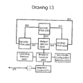
- the Simulation Controller (600) provides some means of supplying simulation data and retrieving simulation data from the Multiport Memory (262). Operation of the Multiport Memory (262) and FPGA devices (260) closely follows such models running on the Accelerator Card. Since operations on the Peripheral Interconnect (270) do not allow retrieving a compiled model from the apparatus shown in Figure 13 , the implementation of models contained within the Non-Volatile Configuration Memory (600) or burned onto FPGA devices is as secure as the device package. The package may be encapsulated so as to erase the model configuration data if the encapsulation is physical interrupted.
- models contained within the encapsulated simulation peripheral shown in Figure 13 must have suitable logic configurations compiled for any supported Operating Context and contained within either the Non-Volatile Configuration Memory (600) or retained in the FPGA (260). Comparable techniques pre-generating logic for all supported Operating Contexts may be used for FPGA devices on the accelerator card at the expense of substantial pre-simulation compilation time and usage of persistent storage capacity.
- Figure 14 illustrates the operating mode executing simulation of an analog partition using the apparatus shown on Figure 12 .
- Execution starts with 612, copying changes in the value of digital and analog objects which are altered outside of the partition and read by one or more equations mapped onto the current FPGA (260).
- Registers and/or memory arrays retain the current value of all objects (analog and digital) referenced or assigned by the current partition (610).
- One or more means of evaluating expressions on either side of a characteristic equation must be provided on the FPGA device (602). Behavioral synthesis techniques for compiling expressions into such logic are well known to those skilled in the art of behavioral synthesis. In order to fit at least one characteristic equation from an equation system onto each FPGA, serial implementations of operators may be required. Such serial implementations for both floating point and integer representations are well-known to those skilled in the art of logic design. Furthermore, the same expression evaluation logic may be used for more than one characteristic equation evaluation using well-known hardware scheduling techniques.
- the value of the left and right hand side of each characteristic equation must be compared (such as by subtraction) and the magnitude of the result compared against the applicable tolerance (typically represented as a literal in storage or embedded in logic configurations). If the magnitude difference between left and right hand sides is less than the tolerance for all equations in the partition, the current object values result in analog solver convergence for the current cycle (604) and partition. Conversely, if the result is greater than the tolerance (605), the analog solver will continue iterating (623).
- Each quantity referenced on other FPGA devices must have a partial delta exported from each FPGA referencing the quantity to all other FPGA devices using the quantity resulting in a global delta (608) for each quantity on each cycle of the analog solver. If the quantity is used more than once on the same FPGA, the delta values may be combined with appropriately higher weighting when the delta is subsequently exported (609). Delta values are then imported (609) and combined to yield a composite delta value for each quantity on each cycle of the analog solver. This delta value is either separately combined on each FPGA using a quantity or exported and re-imported depending on the static availability of time-slots on FPGA pins to encode the delta. Delta values then generate a control signal for each means of up/down changes to the quantity values (601).
- the Analog Solver re-evaluates (611) the Operating Context associated with the quantity values resulting from Step 601. This re-evaluation was previously described using Figure 8 .
- Re-evaluation (611) comprises the constituent Steps 350, 351, 356, 357, 354, 355 and 358.
- the analog solver may continue with another iteration of the FPGA-based analog solver (629) or may complete the current analog solver using a software analog solver (629) via some means of initiating software intervention such as a trap.
- Trap to the software-based solver specifically results from the need to converge over a wider capture range than the hardware provides, resulting from a discontinuity in quantity values or a failure to converge after a specified number of cycles through path 629.
- the software-based analog solver completes it continues with execution of the Digital Simulation Cycle (609).
- any integral or differentials derived from quantity values must be updated (606).
- any quantity or derived quantity values must be copied (607) from the FPGA (260) to Multiport Memory (262).
- the interleaved digital simulation cycle may begin (628).
- the analog solver cycle may begin again (614) until reaching an implied or explicit breakpoint in time or other values.
- Figure 15 shows how both explicit and implicit objects required for simulation of the partition may be partially or totally mapped into memory arrays (650 and 660) associated with the FPGA.
- the FPGA may contain the memory arrays internally or the memory arrays may be external.
- Objects contained in the arrays may include Read-only Literals such as tolerance values (651), Signal values (652), Shared Variables (653), Quantities (654), Terminals (655), Temporaries (656) and local or global Delta values (657).
- Pins used to interconnect logic internal to an FPGA (260) with logic external to the FPGA, such as another FPGA (260) or Multiport Memory (262) were previously used to represent signal values directly or using Time Division Multiplexing (TDM) to implement a digital simulation.
- TDM Time Division Multiplexing
- representation of signals on pins (and associated interconnects) makes inefficient use of scarce pin and interconnect resources since some bits of the value (typically the more significant bits) change infrequently compared to the least significant bits.
- Figure 16 shows an improved, delta-based representation using pins and interconnects to represent the change in object value.
- a bit-wide interconnect may use both edges to represent transfer of a unit defined at compile time, such as a fixed number of charge or energy units (701).
- Such representation is exceptionally compact and makes efficient use of the power required during simulation to charge pins and interconnects. This representation is especially efficient for full-wave and high-frequency analog simulation.
- deltas consist of a sign (such as 703) and one or more bits of value (one bit shown at 704, a range of bits shown as 704 to 705).
- the several delta representations may be time-multiplexed on the same pins and interconnect using either synchronous time division multiplexing (the same delta appears at regular intervals on the pins and interconnect) or may append an additional field to transmit a specific delta value on demand (where the field indicates which delta value is on the pins and wires on a given cycle).
- Analog, mixed-signal and full-wave simulation like many iterative numerical problems, require representation of object values with substantial range and precision in order to maintain accuracy and minimize the impact of representation or arithmetic errors accumulating. Comparable challenges arise in control loops and signal processing applications.
- Figure 18 shows an arithmetic logic unit which accepts input (812 and 813) which may result in an output which is too large to represent, too small to represent or which approximates the least significant bits of the result.
- the arithmetic logic unit, associated data paths and registers is designed to represent a domain of integers from 0 to 7, adding the values 7 and 7 would result in a number too large to represent (overflow), subtracting 7 from 0 would result in a number too small to represent (underflow), dividing 4 by 3 would result in a number which cannot accurately be represent (loss of precision).
- the present invention takes advantage of the flexibility provided by electronically re-configurable logic (FPGA) together with the tight proximity of an Incremental Compiler (5) so as to respond to hardware- detected underflow, overflow or loss of precision by a process consisting of reading the existing state related to the change, modification to the Elaborated Representation (4) so as to increase the domain range, shift the range or scale the range, Recompiling Related State and Logic (803 using 5), Incrementally Binding and Scheduling (451) the new functionality, Incrementally Re-synthesizing (460), Incrementally Scheduling (460), Incrementally Re-timing (460), Incrementally Placing and Routing (461), merging the previous state with the new logic configuration and incrementally re-loading the logic configuration and merged state. The computation then continues at full speed.
- FPGA electronically re-configurable logic
- this innovation facilitates accurate and efficient use of an integer representation rather than requiring the size, latency and power requirements of a floating point representation within the FPGA.
- the resulting integer logic implementation can retain the same range as the floating point representation when required while achieving increased and uniform precision.
- Uniform precision across the entire domain of the representation increases numerical stability and accuracy of iterative numerical applications (such as simulation) since any precision errors introduced by eventual rounding are uniform across the domain. Fortunately with the present invention such rounding need not occur until FPGA resources are exhausted and then in a uniform and instantaneous fashion which further increases numerical accuracy.
- Figure 19 illustrates a method for semi-automatically generating more detailed or more abstract models given an existing, black-box analog or mixed signal component simulation (853) or equivalently an actual device present in a test system allowing external presentation of simulus and response sampling (855).
- Model generation begins with an incrementally formed Template Library (868), detailed in Figure 20 .
- the template library iteratively translates a sequence of model specifications (870) either directly into a tem-plate match against an existing template in the library or indirectly via generation of a matching template via Template Generator (900).
- Each matching template consists of two views: one view as an equation system (perhaps with embedded conditionals and reference to digital interface objects) and the other view as a structural model in which the components are drawn from a small set of generally accepted terminal components.
- the preferred embodiment specifically uses the set of SPICE components augmented with BSIM models and RF/MW models such as transmission lines and specific antenna forms.
- the initial Template Library (868) must begin with a library of existing templates. In the preferred embodiment this library is read in from files and a directory hierarchy using FTL Systems' AIRE/CE File Intermediate Representation (FIR) however those skilled in the art will recognize that other intermediate representations may readily be adapted to the method.
- FIR FTL Systems' AIRE/CE File Intermediate Representation
- the means of Template Selection iterates between a refined specification of the required template (870) and iterative probing of the simulated (853) or actual (855) reference via the means of Test Model Generation and Analysis (851).
- Template selection evolves through three selection phases: a means of matching the template and reference based on the number and type of ports, establishing the VHDL-AMS entity to be generated (904), template matching based on switch-level topology (905) and matching based on equivalent canonical equation formulation (906).
- the preferred embodiment uses Verilog's predefined switch level models for convenience, however those skilled in the art will recognize that other switch level and equivalent representations may be adapted. Matching based on equivalent canonical form will be discussed below.
- equation specifics are fit to the model in the equation fitting step (852).
- Various techniques for experimentally fitting equations to data are well known, such as the excellent summary applied to non-linear and microwave devices by Turlington. Other comparable techniques are well known to those skilled in the art of numerical analysis.
- parameter fitting again using well-known techniques for fitting experimental data to a system of equations. Each refinement in the equation view drives an equivalent, incremental change to the structural view.
- Steps 850, 852 and 854 rely on a common module which provides a means of converting ambiguities in a system of equations into a self-contained test case (consisting of a test bench and stimuli), a means of submitting the test case to a simulated or actual device and a means of responding to 850, 852 and 854.
- interfaces 863 and 864 generate a well-known SPICE deck format and accept a table consisting of a value for each probed quantity at each time step. Other, equivalent formats are well known to those familiar with SPICE simulation.
- the test set interface (865 and 866) uses the same protocol as 863 and 864.
- An interactive test set (written in Perl with network extensions) converts the SPICE inter-face to a set of equivalent General Purpose Interface Bus (GPIB) commands.
- GPIB General Purpose Interface Bus
- Test Model Generation and Analysis uses a parameterized, in-memory representation for the preferred embodiment, such as FTL Systems' AIRE/CE Internal Intermediate Representation (IIR). Other, comparable representations are known to those skilled in the art of intermediate format design and implementation.
- IIR Internal Intermediate Representation
- IIR may be converted into a textual format (867) using an IIR to source code printer.
- IIR to source code printer Such a module is included with FTL Systems' Tauri source code analyzer, however other and comparable mechanisms for printing an intermediate fonnat as text are commonly included in hardware description language compilers.
Landscapes
- Engineering & Computer Science (AREA)
- Computer Hardware Design (AREA)
- Physics & Mathematics (AREA)
- Theoretical Computer Science (AREA)
- Microelectronics & Electronic Packaging (AREA)
- Evolutionary Computation (AREA)
- Geometry (AREA)
- General Engineering & Computer Science (AREA)
- General Physics & Mathematics (AREA)
- Management, Administration, Business Operations System, And Electronic Commerce (AREA)
- Design And Manufacture Of Integrated Circuits (AREA)
- Logic Circuits (AREA)
Applications Claiming Priority (3)
| Application Number | Priority Date | Filing Date | Title |
|---|---|---|---|
| US33188701P | 2001-11-21 | 2001-11-21 | |
| US10/301,173 US7328195B2 (en) | 2001-11-21 | 2002-11-20 | Semi-automatic generation of behavior models continuous value using iterative probing of a device or existing component model |
| EP02789799A EP1456783A4 (fr) | 2001-11-21 | 2002-11-21 | Procede de production semi-automatique et de comparaison comportementale de modeles |
Related Parent Applications (1)
| Application Number | Title | Priority Date | Filing Date |
|---|---|---|---|
| EP02789799.0 Division | 2002-11-21 |
Publications (2)
| Publication Number | Publication Date |
|---|---|
| EP2336920A2 true EP2336920A2 (fr) | 2011-06-22 |
| EP2336920A3 EP2336920A3 (fr) | 2011-08-17 |
Family
ID=26972199
Family Applications (2)
| Application Number | Title | Priority Date | Filing Date |
|---|---|---|---|
| EP10184769A Withdrawn EP2336920A3 (fr) | 2001-11-21 | 2002-11-21 | Procédé pour la génération semi-automatique d'une simulation se fondant sur la exploration iterative |
| EP02789799A Withdrawn EP1456783A4 (fr) | 2001-11-21 | 2002-11-21 | Procede de production semi-automatique et de comparaison comportementale de modeles |
Family Applications After (1)
| Application Number | Title | Priority Date | Filing Date |
|---|---|---|---|
| EP02789799A Withdrawn EP1456783A4 (fr) | 2001-11-21 | 2002-11-21 | Procede de production semi-automatique et de comparaison comportementale de modeles |
Country Status (4)
| Country | Link |
|---|---|
| US (2) | US7328195B2 (fr) |
| EP (2) | EP2336920A3 (fr) |
| AU (1) | AU2002352842A1 (fr) |
| WO (1) | WO2003046775A1 (fr) |
Cited By (2)
| Publication number | Priority date | Publication date | Assignee | Title |
|---|---|---|---|---|
| WO2013154448A1 (fr) * | 2012-04-10 | 2013-10-17 | Cadence Design Systems, Inc. | Procédé et système d'établissement automatique d'un environnement de débogage de cellule paramétrée hiérarchique (pcell) |
| WO2017123238A1 (fr) * | 2016-01-15 | 2017-07-20 | Hewlett Packard Enterprise Development Lp | Circuit multicœur à signalisation mixte |
Families Citing this family (84)
| Publication number | Priority date | Publication date | Assignee | Title |
|---|---|---|---|---|
| US8862452B2 (en) * | 2001-02-14 | 2014-10-14 | Xio, Inc. | Control system simulator and simplified interconnection control system |
| US20030154059A1 (en) * | 2001-11-30 | 2003-08-14 | Jorg-Uwe Feldmann | Simulation apparatus and simulation method for a system having analog and digital elements |
| US6732060B1 (en) * | 2002-05-06 | 2004-05-04 | Adaptec, Inc. | System and method for an interface invariant test case |
| US7299427B2 (en) * | 2002-08-30 | 2007-11-20 | Lsi Corporation | Radio prototyping system |
| US20040059561A1 (en) * | 2002-09-25 | 2004-03-25 | Ilya Gluhovsky | Method and apparatus for determining output uncertainty of computer system models using sensitivity characterization |
| WO2004048909A2 (fr) * | 2002-11-21 | 2004-06-10 | Arizona Board Of Regents | Procede et systeme d'analyse spectrale vectorielle comprimee pour blocs rf non lineaires |
| US8224636B2 (en) * | 2002-12-17 | 2012-07-17 | Cadence Design Systems, Inc. | Method and system for implementing parallel execution in a computing system and in a circuit simulator |
| US7599821B1 (en) * | 2003-04-30 | 2009-10-06 | Cadence Design Systems, Inc. | Mixed language simulation cycle for analog mixed-signal circuit design and simulation |
| US7308659B1 (en) * | 2003-08-14 | 2007-12-11 | Altera Corporation | Apparatus and method for RTL modeling of a register |
| US7251803B2 (en) * | 2003-11-05 | 2007-07-31 | Peter Ramyalal Suaris | Memory re-implementation for field programmable gate arrays |
| DE102004014178B4 (de) * | 2004-03-23 | 2006-04-27 | Infineon Technologies Ag | Rechnergestütztes, automatisiertes Verfahren zur Verifikation analoger Schaltungen |
| US7509618B1 (en) * | 2004-05-12 | 2009-03-24 | Altera Corporation | Method and apparatus for facilitating an adaptive electronic design automation tool |
| JP4080464B2 (ja) * | 2004-07-14 | 2008-04-23 | 松下電器産業株式会社 | 検証ベクタ生成方法およびこれを用いた電子回路の検証方法 |
| US7251795B2 (en) * | 2004-09-27 | 2007-07-31 | Cadence Design Systems, Inc. | Connecting verilog-AMS and VHDL-AMS components in a mixed-language mixed-signal design |
| US20060212279A1 (en) * | 2005-01-31 | 2006-09-21 | The Board of Trustees of the University of Illinois and | Methods for efficient solution set optimization |
| US20060236303A1 (en) * | 2005-03-29 | 2006-10-19 | Wilson Thomas G Jr | Dynamically adjustable simulator, such as an electric circuit simulator |
| US7260792B2 (en) * | 2005-05-10 | 2007-08-21 | Cadence Design Systems, Inc. | Modeling a mixed-language mixed-signal design |
| US20060277020A1 (en) * | 2005-06-02 | 2006-12-07 | Tharas Systems | A reconfigurable system for verification of electronic circuits using high-speed serial links to connect asymmetrical evaluation and canvassing instruction processors |
| US7444610B1 (en) * | 2005-08-03 | 2008-10-28 | Xilinx, Inc. | Visualizing hardware cost in high level modeling systems |
| US7840397B2 (en) * | 2005-12-02 | 2010-11-23 | Derek Chiou | Simulation method |
| US8001537B1 (en) * | 2005-12-05 | 2011-08-16 | Altera Corporation | Method and apparatus for compiling programmable logic device configurations |
| US7711534B2 (en) * | 2005-12-09 | 2010-05-04 | International Business Machines Corporation | Method and system of design verification |
| EP1964010B1 (fr) * | 2005-12-19 | 2017-07-19 | Synopsys, Inc. | Simulation de circuit parallele a plusieurs allures |
| US9489290B1 (en) * | 2005-12-30 | 2016-11-08 | The Mathworks, Inc. | Scheduling tests based on a valuation system |
| US7739092B1 (en) * | 2006-01-31 | 2010-06-15 | Xilinx, Inc. | Fast hardware co-simulation reset using partial bitstreams |
| US7979365B2 (en) * | 2006-01-31 | 2011-07-12 | The Board Of Trustees Of The University Of Illinois | Methods and systems for interactive computing |
| US8131656B2 (en) * | 2006-01-31 | 2012-03-06 | The Board Of Trustees Of The University Of Illinois | Adaptive optimization methods |
| US7565280B2 (en) | 2006-02-17 | 2009-07-21 | National Instruments Corporation | Solver for simulating a system in real time on a programmable hardware element |
| JP2007316731A (ja) * | 2006-05-23 | 2007-12-06 | Nec Electronics Corp | Lsi設計支援装置 |
| GB2442496A (en) * | 2006-10-02 | 2008-04-09 | Univ Sheffield | Evaluating displacements at discontinuities within a body |
| US8117606B2 (en) * | 2007-06-04 | 2012-02-14 | Infosys Technologies Ltd. | System and method for application migration in a grid computing environment |
| JP5109143B2 (ja) * | 2007-06-28 | 2012-12-26 | 株式会社東芝 | 検証装置および検証方法 |
| US8561037B2 (en) * | 2007-08-29 | 2013-10-15 | Convey Computer | Compiler for generating an executable comprising instructions for a plurality of different instruction sets |
| US8095735B2 (en) * | 2008-08-05 | 2012-01-10 | Convey Computer | Memory interleave for heterogeneous computing |
| US8122229B2 (en) * | 2007-09-12 | 2012-02-21 | Convey Computer | Dispatch mechanism for dispatching instructions from a host processor to a co-processor |
| US9015399B2 (en) * | 2007-08-20 | 2015-04-21 | Convey Computer | Multiple data channel memory module architecture |
| US8156307B2 (en) * | 2007-08-20 | 2012-04-10 | Convey Computer | Multi-processor system having at least one processor that comprises a dynamically reconfigurable instruction set |
| US9710384B2 (en) | 2008-01-04 | 2017-07-18 | Micron Technology, Inc. | Microprocessor architecture having alternative memory access paths |
| US8001515B2 (en) * | 2007-12-21 | 2011-08-16 | National Semiconductor Corporation | Simultaneous optimization of analog design parameters using a cost function of responses |
| US20090222253A1 (en) * | 2008-03-03 | 2009-09-03 | Thomas Jay Sheffler | System and Method for Switch-Level Linear Simulation Using Verilog |
| US7921195B2 (en) * | 2008-06-09 | 2011-04-05 | International Business Machines Corporation | Optimizing service processing based on business information, operational intelligence, and self-learning |
| US8266571B2 (en) | 2008-06-10 | 2012-09-11 | Oasis Tooling, Inc. | Methods and devices for independent evaluation of cell integrity, changes and origin in chip design for production workflow |
| US8261228B1 (en) | 2008-10-01 | 2012-09-04 | Cadence Design Systems, Inc. | Technique for modeling parasitics from layout during circuit design and for parasitic aware circuit design using modes of varying accuracy |
| US20100115233A1 (en) * | 2008-10-31 | 2010-05-06 | Convey Computer | Dynamically-selectable vector register partitioning |
| US8205066B2 (en) * | 2008-10-31 | 2012-06-19 | Convey Computer | Dynamically configured coprocessor for different extended instruction set personality specific to application program with shared memory storing instructions invisibly dispatched from host processor |
| US9418185B2 (en) | 2008-12-19 | 2016-08-16 | Viswanathan Madhavan | Thermal modeling of an orthogonal machining process |
| US8201137B1 (en) | 2009-03-06 | 2012-06-12 | Cadence Design Systems, Inc. | Method and apparatus for AMS simulation of integrated circuit design |
| US8712751B2 (en) * | 2009-05-08 | 2014-04-29 | Qualcomm Incorporated | System and method of verification of analog circuits |
| US8156459B1 (en) * | 2009-11-10 | 2012-04-10 | Xilinx, Inc. | Detecting differences between high level block diagram models |
| US8423745B1 (en) | 2009-11-16 | 2013-04-16 | Convey Computer | Systems and methods for mapping a neighborhood of data to general registers of a processing element |
| JP5692739B2 (ja) * | 2010-03-11 | 2015-04-01 | インターナショナル・ビジネス・マシーンズ・コーポレーションInternational Business Machines Corporation | 常微分方程式を解くための方法、プログラム及びシステム |
| US8676551B1 (en) * | 2010-03-12 | 2014-03-18 | The Mathworks, Inc. | Multi-solver simulation of dynamic systems in a modeling environment |
| ES2955230T3 (es) * | 2010-03-22 | 2023-11-29 | Xio Inc | Simulador de sistema de control mejorado y sistema de control de interconexión simplificado |
| US8504973B1 (en) | 2010-04-15 | 2013-08-06 | Altera Corporation | Systems and methods for generating a test environment and test system surrounding a design of an integrated circuit |
| US8782434B1 (en) | 2010-07-15 | 2014-07-15 | The Research Foundation For The State University Of New York | System and method for validating program execution at run-time |
| US8555243B2 (en) * | 2010-07-30 | 2013-10-08 | National Instruments Corporation | Generating and debugging timing accurate simulations in a graphical specification and constraint language |
| US9436441B1 (en) * | 2010-12-08 | 2016-09-06 | The Mathworks, Inc. | Systems and methods for hardware resource sharing |
| EP2718860A4 (fr) | 2011-06-10 | 2015-03-04 | Oasis Tooling Inc | Identification de propriété intellectuelle de conception de puce hiérarchique par résumés |
| US8515715B2 (en) * | 2011-06-17 | 2013-08-20 | International Business Machines Corporation | Method, system and program storage device for simulating electronic device performance as a function of process variations |
| US9053272B2 (en) * | 2011-07-15 | 2015-06-09 | Tictran Corp. | Method and apparatus of hardware acceleration of EDA tools for a programmable logic device |
| US10430190B2 (en) | 2012-06-07 | 2019-10-01 | Micron Technology, Inc. | Systems and methods for selectively controlling multithreaded execution of executable code segments |
| US9020797B2 (en) * | 2012-06-14 | 2015-04-28 | Cadence Design Systems, Inc. | Integrated circuit simulation using analog power domain in analog block mixed signal |
| US20140046634A1 (en) * | 2012-08-13 | 2014-02-13 | Caterpillar Inc. | Facility Design and Management Systems Using Order Processing |
| US9122873B2 (en) | 2012-09-14 | 2015-09-01 | The Research Foundation For The State University Of New York | Continuous run-time validation of program execution: a practical approach |
| CN103729490A (zh) * | 2012-10-15 | 2014-04-16 | 飞思卡尔半导体公司 | 混合信号ip核原型设计系统 |
| US10198540B1 (en) * | 2013-09-27 | 2019-02-05 | Cadence Design Systems, Inc. | System and method for profiling during an electronic design simulation |
| CN103559238B (zh) * | 2013-10-25 | 2016-08-24 | 华东师范大学 | 一种多复用智能卡形式化建模与验证方法 |
| KR102100161B1 (ko) | 2014-02-04 | 2020-04-14 | 삼성전자주식회사 | Gpu 데이터 캐싱 방법 및 그에 따른 데이터 프로세싱 시스템 |
| US9934339B2 (en) | 2014-08-15 | 2018-04-03 | Wichita State University | Apparatus and method for simulating machining and other forming operations |
| CN105653744A (zh) * | 2014-11-13 | 2016-06-08 | 中芯国际集成电路制造(上海)有限公司 | 版图布局的设计方法及装置 |
| US10089423B2 (en) * | 2015-05-21 | 2018-10-02 | Mayo Foundation For Medical Education And Research | Systems and methods for efficiently simulating wave propagation in viscoelastic media |
| US10698320B2 (en) * | 2016-12-14 | 2020-06-30 | Taiwan Semiconductor Manufacturing Co., Ltd. | Method for optimized wafer process simulation |
| WO2018235004A1 (fr) * | 2017-06-22 | 2018-12-27 | Sendyne Corporation | Résolveur d'équations différentielles stochastiques |
| CN110268404B (zh) * | 2019-05-09 | 2020-09-25 | 长江存储科技有限责任公司 | 用于功能对等检测中的仿真方法 |
| US10839124B1 (en) * | 2019-06-26 | 2020-11-17 | Amazon Technologies, Inc. | Interactive compilation of software to a hardware language to satisfy formal verification constraints |
| US12523680B2 (en) | 2019-10-04 | 2026-01-13 | International Business Machines Corporation | Spur detection in a sampled waveform in a mixed analog/digital system using the phase of the frequency response |
| US12188964B2 (en) | 2019-10-04 | 2025-01-07 | International Business Machines Corporation | Spur detection in a sampled waveform in a mixed analog/digital system using the magnitude of the frequency response |
| WO2021154613A1 (fr) * | 2020-01-30 | 2021-08-05 | Optumsoft, Inc. | Génération automatique de logique de décision de commande pour des systèmes modifiés complexes à partir d'un modèle physique dynamique |
| US12259453B2 (en) * | 2020-12-28 | 2025-03-25 | Murata Manufacturing Co., Ltd. | Systems and methods for vector-short-open-calibration de-embedding of microwave circuits |
| CN112967310B (zh) * | 2021-02-04 | 2023-07-14 | 成都国翼电子技术有限公司 | 一种基于fpga的模板匹配加速方法 |
| US11334702B1 (en) * | 2021-02-11 | 2022-05-17 | Siemens Industry Software Inc. | Mixed-signal simulation for complex design topologies |
| US11487925B1 (en) * | 2021-07-02 | 2022-11-01 | Changxin Memory Technologies, Inc. | Simulation method, apparatus, and device, and storage medium |
| CN113722867B (zh) * | 2021-08-30 | 2025-03-18 | 全球能源互联网研究院有限公司 | 一种电路解算方法、装置、电子设备及存储介质 |
| US12387022B2 (en) * | 2022-03-02 | 2025-08-12 | Taiwan Semiconductor Manufacturing Company, Ltd. | Apparatus and method of optimizing an integrated circuit design |
Citations (1)
| Publication number | Priority date | Publication date | Assignee | Title |
|---|---|---|---|---|
| US5999734A (en) | 1997-10-21 | 1999-12-07 | Ftl Systems, Inc. | Compiler-oriented apparatus for parallel compilation, simulation and execution of computer programs and hardware models |
Family Cites Families (64)
| Publication number | Priority date | Publication date | Assignee | Title |
|---|---|---|---|---|
| US4306286A (en) | 1979-06-29 | 1981-12-15 | International Business Machines Corporation | Logic simulation machine |
| US4677587A (en) | 1985-05-14 | 1987-06-30 | Sanders Associates, Inc. | Program simulation system including means for ensuring interactive enforcement of constraints |
| US4734879A (en) * | 1985-09-24 | 1988-03-29 | Lin Hung C | Analog computing method of solving a second order differential equation |
| US4937770A (en) | 1986-02-07 | 1990-06-26 | Teradyne, Inc. | Simulation system |
| US4835726A (en) | 1986-06-26 | 1989-05-30 | University Of Toronto Innovations Foundation | Apparatus for analog simulation of a circuit |
| US4827427A (en) | 1987-03-05 | 1989-05-02 | Hyduke Stanley M | Instantaneous incremental compiler for producing logic circuit designs |
| JPS63223869A (ja) | 1987-03-13 | 1988-09-19 | Hitachi Ltd | プログラム生成方法 |
| US5265040A (en) * | 1987-08-28 | 1993-11-23 | Hitachi, Ltd. | Method and device for displaying information on simulation result in a numerical simulation system |
| US5146583A (en) | 1987-09-25 | 1992-09-08 | Matsushita Electric Industrial Co., Ltd. | Logic design system for creating circuit configuration by generating parse tree from hardware description language and optimizing text level redundancy thereof |
| US4815024A (en) | 1987-11-12 | 1989-03-21 | University Of Toronto, Innovations Foundation | Simulation apparatus |
| US4868770A (en) | 1987-12-02 | 1989-09-19 | Analogy, Inc. | Simulation results enhancement method and system |
| JP2583949B2 (ja) | 1988-03-10 | 1997-02-19 | 松下電器産業株式会社 | 論理シミュレーション方法と論理シミュレーション装置 |
| JP2609280B2 (ja) | 1988-04-22 | 1997-05-14 | 株式会社日立製作所 | シミュレーション方法 |
| US5452231A (en) | 1988-10-05 | 1995-09-19 | Quickturn Design Systems, Inc. | Hierarchically connected reconfigurable logic assembly |
| US5329470A (en) | 1988-12-02 | 1994-07-12 | Quickturn Systems, Inc. | Reconfigurable hardware emulation system |
| US5111413A (en) | 1989-03-24 | 1992-05-05 | Vantage Analysis Systems, Inc. | Computer-aided engineering |
| US4985860A (en) | 1989-06-21 | 1991-01-15 | Martin Vlach | Mixed-mode-simulator interface |
| US5105373A (en) | 1990-01-22 | 1992-04-14 | Texas Instruments Incorporated | Method of simulating the operation of a circuit having analog and digital circuit parts |
| US5867399A (en) | 1990-04-06 | 1999-02-02 | Lsi Logic Corporation | System and method for creating and validating structural description of electronic system from higher-level and behavior-oriented description |
| US5467291A (en) * | 1991-09-09 | 1995-11-14 | Hewlett-Packard Company | Measurement-based system for modeling and simulation of active semiconductor devices over an extended operating frequency range |
| JP2956800B2 (ja) | 1991-09-19 | 1999-10-04 | 株式会社日立製作所 | 連立一次方程式に関する計算装置 |
| JP3082987B2 (ja) | 1991-10-09 | 2000-09-04 | 株式会社日立製作所 | ミックスモードシミュレーション方法 |
| CA2076293A1 (fr) | 1991-10-11 | 1993-04-12 | Prathima Agrawal | Ordinateur a multiprocesseur servant a resoudre des ensembles d'equations |
| US5297066A (en) | 1991-10-22 | 1994-03-22 | National Semiconductor Corporation | Digital circuit simulation of analog/digital circuits |
| US5450554A (en) | 1991-11-11 | 1995-09-12 | Matsushita Electric Industrial Co., Ltd. | Apparatus for detecting possibility of parallel processing and method thereof and a program translation apparatus utilized therein |
| US5794005A (en) | 1992-01-21 | 1998-08-11 | The United States Of America As Represented By The Administrator Of The National Aeronautics And Space Administration | Synchronous parallel emulation and discrete event simulation system with self-contained simulation objects and active event objects |
| US5475830A (en) | 1992-01-31 | 1995-12-12 | Quickturn Design Systems, Inc. | Structure and method for providing a reconfigurable emulation circuit without hold time violations |
| US5335191A (en) | 1992-03-27 | 1994-08-02 | Cadence Design Systems, Inc. | Method and means for communication between simulation engine and component models in a circuit simulator |
| US5913051A (en) | 1992-10-09 | 1999-06-15 | Texas Instruments Incorporated | Method of simultaneous simulation of a complex system comprised of objects having structure state and parameter information |
| US5477474A (en) | 1992-10-29 | 1995-12-19 | Altera Corporation | Computer logic simulation with dynamic modeling |
| US5361373A (en) | 1992-12-11 | 1994-11-01 | Gilson Kent L | Integrated circuit computing device comprising a dynamically configurable gate array having a microprocessor and reconfigurable instruction execution means and method therefor |
| US5528508A (en) | 1993-02-19 | 1996-06-18 | International Business Machines Corporation | System and method for verifying a hierarchical circuit design |
| US5418953A (en) | 1993-04-12 | 1995-05-23 | Loral/Rohm Mil-Spec Corp. | Method for automated deployment of a software program onto a multi-processor architecture |
| US5812431A (en) | 1994-06-13 | 1998-09-22 | Cadence Design Systems, Inc. | Method and apparatus for a simplified system simulation description |
| JPH07307771A (ja) | 1994-05-12 | 1995-11-21 | Kokusai Denshin Denwa Co Ltd <Kdd> | プロトコルの論理検証方法 |
| JPH0830660A (ja) | 1994-07-12 | 1996-02-02 | Toshiba Corp | 半導体集積回路の並列シミュレータ |
| US5752000A (en) | 1994-08-02 | 1998-05-12 | Cadence Design Systems, Inc. | System and method for simulating discrete functions using ordered decision arrays |
| JP3297213B2 (ja) | 1994-08-18 | 2002-07-02 | 株式会社東芝 | 集積回路シミュレータ及び集積回路のシミュレーション方法 |
| US5455938A (en) | 1994-09-14 | 1995-10-03 | Ahmed; Sultan | Network based machine instruction generator for design verification |
| US5682392A (en) | 1994-09-28 | 1997-10-28 | Teradyne, Inc. | Method and apparatus for the automatic generation of boundary scan description language files |
| GB2338325B (en) | 1994-10-03 | 2000-02-09 | Univ Westminster | Data processing method and apparatus for parallel discrete event simulation |
| US5715373A (en) | 1994-10-20 | 1998-02-03 | Tandem Computers Incorporated | Method and apparatus for preparing a suite of test scripts for testing a proposed network management application |
| US5715184A (en) | 1995-01-23 | 1998-02-03 | Motorola, Inc. | Method of parallel simulation of standard cells on a distributed computer system |
| US5821773A (en) | 1995-09-06 | 1998-10-13 | Altera Corporation | Look-up table based logic element with complete permutability of the inputs to the secondary signals |
| JP2888512B2 (ja) | 1995-09-22 | 1999-05-10 | 三菱電機マイコン機器ソフトウエア株式会社 | エミュレーション装置 |
| US5768562A (en) | 1995-09-26 | 1998-06-16 | Altera Corporation | Methods for implementing logic in auxiliary components associated with programmable logic array devices |
| US5870588A (en) * | 1995-10-23 | 1999-02-09 | Interuniversitair Micro-Elektronica Centrum(Imec Vzw) | Design environment and a design method for hardware/software co-design |
| US5710901A (en) | 1995-12-29 | 1998-01-20 | Tci Summitrak Of Texas, Inc. | Method and apparatus for validating data entered by a user |
| US5802349A (en) | 1996-01-22 | 1998-09-01 | Motorola, Inc. | Method for generating an optimized integrated circuit cell library |
| JP3645346B2 (ja) | 1996-01-22 | 2005-05-11 | 富士通株式会社 | 論理シミュレーション装置 |
| US5867397A (en) * | 1996-02-20 | 1999-02-02 | John R. Koza | Method and apparatus for automated design of complex structures using genetic programming |
| US5774693A (en) | 1996-02-28 | 1998-06-30 | Kaimei Electronic Corp. | Multiprocessor parallel computing device for application to the execution of a numerical simulation software program |
| US5768159A (en) | 1996-05-02 | 1998-06-16 | Northern Telecom Limited | Method of simulating AC timing characteristics of integrated circuits |
| US5768567A (en) | 1996-05-14 | 1998-06-16 | Mentor Graphics Corporation | Optimizing hardware and software co-simulator |
| GB9700798D0 (en) | 1997-01-16 | 1997-03-05 | Int Computers Ltd | Digital system simulation |
| US5956261A (en) | 1997-03-13 | 1999-09-21 | International Business Machines Corporation | In-transit message detection for global virtual time calculation in parrallel time warp simulation |
| US6321366B1 (en) * | 1997-05-02 | 2001-11-20 | Axis Systems, Inc. | Timing-insensitive glitch-free logic system and method |
| US6009256A (en) | 1997-05-02 | 1999-12-28 | Axis Systems, Inc. | Simulation/emulation system and method |
| US6263301B1 (en) | 1998-08-19 | 2001-07-17 | Cadence Design Systems, Inc. | Method and apparatus for storing and viewing data generated from a computer simulation of an integrated circuit |
| US6108494A (en) | 1998-08-24 | 2000-08-22 | Mentor Graphics Corporation | Optimizing runtime communication processing between simulators |
| DE19926206C2 (de) | 1999-06-09 | 2003-04-03 | Daimler Chrysler Ag | Fahrzeugelektrik-Konfigurationssystem |
| US6480816B1 (en) * | 1999-06-14 | 2002-11-12 | Sanjay Dhar | Circuit simulation using dynamic partitioning and on-demand evaluation |
| US6427224B1 (en) * | 2000-01-31 | 2002-07-30 | International Business Machines Corporation | Method for efficient verification of system-on-chip integrated circuit designs including an embedded processor |
| US7277832B2 (en) * | 2001-05-04 | 2007-10-02 | Bigwood Technology, Inc. | Dynamical method for obtaining global optimal solution of general nonlinear programming problems |
-
2002
- 2002-11-20 US US10/301,173 patent/US7328195B2/en not_active Expired - Fee Related
- 2002-11-21 AU AU2002352842A patent/AU2002352842A1/en not_active Abandoned
- 2002-11-21 EP EP10184769A patent/EP2336920A3/fr not_active Withdrawn
- 2002-11-21 WO PCT/US2002/037351 patent/WO2003046775A1/fr not_active Ceased
- 2002-11-21 EP EP02789799A patent/EP1456783A4/fr not_active Withdrawn
-
2006
- 2006-01-10 US US11/328,629 patent/US7539602B2/en not_active Expired - Fee Related
Patent Citations (1)
| Publication number | Priority date | Publication date | Assignee | Title |
|---|---|---|---|---|
| US5999734A (en) | 1997-10-21 | 1999-12-07 | Ftl Systems, Inc. | Compiler-oriented apparatus for parallel compilation, simulation and execution of computer programs and hardware models |
Cited By (4)
| Publication number | Priority date | Publication date | Assignee | Title |
|---|---|---|---|---|
| WO2013154448A1 (fr) * | 2012-04-10 | 2013-10-17 | Cadence Design Systems, Inc. | Procédé et système d'établissement automatique d'un environnement de débogage de cellule paramétrée hiérarchique (pcell) |
| US8719745B2 (en) | 2012-04-10 | 2014-05-06 | Cadence Design Systems, Inc. | Method and system for automatically establishing hierarchical parameterized cell (PCELL) debugging environment |
| WO2017123238A1 (fr) * | 2016-01-15 | 2017-07-20 | Hewlett Packard Enterprise Development Lp | Circuit multicœur à signalisation mixte |
| US10771081B2 (en) | 2016-01-15 | 2020-09-08 | Hewlett Packard Enterprise Development Lp | Multi-core circuit with mixed signaling |
Also Published As
| Publication number | Publication date |
|---|---|
| EP2336920A3 (fr) | 2011-08-17 |
| WO2003046775A1 (fr) | 2003-06-05 |
| EP1456783A1 (fr) | 2004-09-15 |
| WO2003046775B1 (fr) | 2004-04-08 |
| US7539602B2 (en) | 2009-05-26 |
| US20060241921A1 (en) | 2006-10-26 |
| EP1456783A4 (fr) | 2006-09-06 |
| US7328195B2 (en) | 2008-02-05 |
| US20030154061A1 (en) | 2003-08-14 |
| AU2002352842A1 (en) | 2003-06-10 |
Similar Documents
| Publication | Publication Date | Title |
|---|---|---|
| US7539602B2 (en) | Accelerating simulation of differential equation systems having continuous behavior | |
| US20030149962A1 (en) | Simulation of designs using programmable processors and electronically re-configurable logic arrays | |
| Ferrandi et al. | Bambu: an open-source research framework for the high-level synthesis of complex applications | |
| Gokhale et al. | Reconfigurable computing: accelerating computation with field-programmable gate arrays | |
| US8205175B2 (en) | Structured algorithmic programming language approach to system design | |
| US5933356A (en) | Method and system for creating and verifying structural logic model of electronic design from behavioral description, including generation of logic and timing models | |
| US6135647A (en) | System and method for representing a system level RTL design using HDL independent objects and translation to synthesizable RTL code | |
| US5493508A (en) | Specification and design of complex digital systems | |
| US6964029B2 (en) | System and method for partitioning control-dataflow graph representations | |
| US10733343B2 (en) | System and method for the design of digital hardware | |
| US9075624B2 (en) | Compilation of system designs | |
| US20030074177A1 (en) | System, method and article of manufacture for a simulator plug-in for co-simulation purposes | |
| EP0463301A2 (fr) | Méthode pour l'obtention de descriptions structurelles à bas niveau exécutables et réalisations physiques valables de circuits et systèmes à partir de spécifications sémantiques à haut niveau et leurs descriptions | |
| US20020199173A1 (en) | System, method and article of manufacture for a debugger capable of operating across multiple threads and lock domains | |
| US20030037321A1 (en) | System, method and article of manufacture for extensions in a programming lanauage capable of programming hardware architectures | |
| WO2011156234A1 (fr) | Systèmes et procédés de conception, de synthèse, de simulation, et de modélisation de circuits | |
| WO2003056475A2 (fr) | Systeme, procede et article de fabrication permettant d'estimer une performance potentielle d'une co-conception a partir d'une specification executable | |
| WO2003056473A2 (fr) | Systeme, procede et article de fabrication servant au profilage d'un modele materiel executable sur la base d'appels a des fonctions de profilage | |
| WO2003056472A2 (fr) | Systeme, procede et article de fabrication servant au profilage d'un modele materiel ameliore | |
| WO2003056474A1 (fr) | Systeme, procede et article de fabrication servant au profilage dynamique de transferts memoire dans un programme | |
| Vahid et al. | Functional partitioning improvements over structural partitioning for packaging constraints and synthesis: tool performance | |
| Ferrandi et al. | High-Level Synthesis Developments in the Context of European Space Technology Research (Invited Talk) | |
| Hsu et al. | Digital design from concept to prototype in hours | |
| Mathaikutty | Metamodeling driven IP reuse for system-on-chip integration and microprocessor design | |
| Vahid et al. | SpecCharts: A language for system level specification and synthesis |
Legal Events
| Date | Code | Title | Description |
|---|---|---|---|
| PUAI | Public reference made under article 153(3) epc to a published international application that has entered the european phase |
Free format text: ORIGINAL CODE: 0009012 |
|
| AC | Divisional application: reference to earlier application |
Ref document number: 1456783 Country of ref document: EP Kind code of ref document: P |
|
| AK | Designated contracting states |
Kind code of ref document: A2 Designated state(s): AT BE BG CH CY CZ DE DK EE ES FI FR GB GR IE IT LI LU MC NL PT SE SK TR |
|
| PUAL | Search report despatched |
Free format text: ORIGINAL CODE: 0009013 |
|
| AK | Designated contracting states |
Kind code of ref document: A3 Designated state(s): AT BE BG CH CY CZ DE DK EE ES FI FR GB GR IE IT LI LU MC NL PT SE SK TR |
|
| RIC1 | Information provided on ipc code assigned before grant |
Ipc: G06F 17/50 20060101AFI20110712BHEP Ipc: G06F 9/45 20060101ALI20110712BHEP |
|
| 17P | Request for examination filed |
Effective date: 20120217 |
|
| 17Q | First examination report despatched |
Effective date: 20130723 |
|
| STAA | Information on the status of an ep patent application or granted ep patent |
Free format text: STATUS: THE APPLICATION HAS BEEN WITHDRAWN |
|
| 18W | Application withdrawn |
Effective date: 20161013 |