EP2337060B1 - Structures d'électrode pour lampe de décharge - Google Patents
Structures d'électrode pour lampe de décharge Download PDFInfo
- Publication number
- EP2337060B1 EP2337060B1 EP20100190701 EP10190701A EP2337060B1 EP 2337060 B1 EP2337060 B1 EP 2337060B1 EP 20100190701 EP20100190701 EP 20100190701 EP 10190701 A EP10190701 A EP 10190701A EP 2337060 B1 EP2337060 B1 EP 2337060B1
- Authority
- EP
- European Patent Office
- Prior art keywords
- electrode
- raised features
- head portion
- wires
- coil
- Prior art date
- Legal status (The legal status is an assumption and is not a legal conclusion. Google has not performed a legal analysis and makes no representation as to the accuracy of the status listed.)
- Not-in-force
Links
- WFKWXMTUELFFGS-UHFFFAOYSA-N tungsten Chemical compound [W] WFKWXMTUELFFGS-UHFFFAOYSA-N 0.000 claims description 13
- 229910052721 tungsten Inorganic materials 0.000 claims description 12
- 239000010937 tungsten Substances 0.000 claims description 12
- 238000004519 manufacturing process Methods 0.000 claims description 6
- 238000000034 method Methods 0.000 claims description 6
- 239000011295 pitch Substances 0.000 description 15
- QSHDDOUJBYECFT-UHFFFAOYSA-N mercury Chemical compound [Hg] QSHDDOUJBYECFT-UHFFFAOYSA-N 0.000 description 5
- 229910052753 mercury Inorganic materials 0.000 description 5
- 238000001704 evaporation Methods 0.000 description 4
- 230000008020 evaporation Effects 0.000 description 4
- 238000002844 melting Methods 0.000 description 3
- 238000004804 winding Methods 0.000 description 3
- 238000009529 body temperature measurement Methods 0.000 description 2
- 239000011248 coating agent Substances 0.000 description 2
- 238000000576 coating method Methods 0.000 description 2
- 238000013461 design Methods 0.000 description 2
- 239000007772 electrode material Substances 0.000 description 2
- 238000005530 etching Methods 0.000 description 2
- 230000012447 hatching Effects 0.000 description 2
- 239000010410 layer Substances 0.000 description 2
- 230000008018 melting Effects 0.000 description 2
- 230000005855 radiation Effects 0.000 description 2
- 238000004616 Pyrometry Methods 0.000 description 1
- 230000015572 biosynthetic process Effects 0.000 description 1
- 230000015556 catabolic process Effects 0.000 description 1
- 238000001816 cooling Methods 0.000 description 1
- 239000007799 cork Substances 0.000 description 1
- 238000006731 degradation reaction Methods 0.000 description 1
- 238000009792 diffusion process Methods 0.000 description 1
- 238000010891 electric arc Methods 0.000 description 1
- 238000005755 formation reaction Methods 0.000 description 1
- 238000000227 grinding Methods 0.000 description 1
- 230000017525 heat dissipation Effects 0.000 description 1
- 238000003754 machining Methods 0.000 description 1
- 239000000463 material Substances 0.000 description 1
- 238000001393 microlithography Methods 0.000 description 1
- 238000005459 micromachining Methods 0.000 description 1
- 238000012986 modification Methods 0.000 description 1
- 230000004048 modification Effects 0.000 description 1
- 238000001953 recrystallisation Methods 0.000 description 1
- 238000007493 shaping process Methods 0.000 description 1
- 238000004088 simulation Methods 0.000 description 1
- 239000002356 single layer Substances 0.000 description 1
- 238000012360 testing method Methods 0.000 description 1
Images

Classifications
-
- H—ELECTRICITY
- H01—ELECTRIC ELEMENTS
- H01J—ELECTRIC DISCHARGE TUBES OR DISCHARGE LAMPS
- H01J61/00—Gas-discharge or vapour-discharge lamps
- H01J61/02—Details
- H01J61/04—Electrodes; Screens; Shields
- H01J61/06—Main electrodes
- H01J61/073—Main electrodes for high-pressure discharge lamps
- H01J61/0732—Main electrodes for high-pressure discharge lamps characterised by the construction of the electrode
Definitions
- the present invention relates generally to electrode structures for discharge lamps.
- Electrodes in short-arc discharge lamps typically operate in a high-temperature environment. Reducing the operating temperature of the electrodes is desirable in order to reduce degradation from evaporation and extend the lifetime of the lamp.
- the electrode operating temperature is determined by the electrical power input, which heats electrodes, and Planck's radiation law (i.e., the electromagnetic emission of an electrode, which results in the electrode cooling).
- Planck's radiation law i.e., the electromagnetic emission of an electrode, which results in the electrode cooling.
- the emissivity of an electrode structure is important parameter in discharge lamp design.
- high-power DC lamps used in microlithography include massive anodes that are coated or microstructured to increase emissivity. Such anodes are expensive and not practical in lower-power, short-arc lamps.
- This technique also has the drawback that neither the coating or microstructure can be applied as close to a front portion of an electrode as desired because a non-tungsten coating will either melt or sublimate at temperatures approaching the tungsten melting point. Moreover, re-crystallization and surface diffusion will destroy tungsten microstructures over time.
- Massive anodes are also not practical in some lamps because electrode size restrictions of many discharge lamps. That is, many discharge lamps are designed to accommodate only electrodes with small diameters or widths. Thus it is not always possible to reduce the electrode operating temperature at a given electrical power input by greatly increasing the size of an electrode.
- FIG. 1 shows a conventional electrode structure for use in a ultra-high-pressure mercury lamp.
- Coil 102 is tightly wound around the electrode shaft portion 104 in one or more layers to form electrode head portion 106.
- Front portion 108 is condensed by over-melting the ends of coil 102.
- the electrode temperature is determined by the size of electrode 100, which in turn is determined by the length of coil 102, the number of coiled layers, and the diameter (or width) of the wires of coil 102.
- FIG. 2 shows another conventional electrode structure for use in a ultra-high-pressure mercury lamp.
- Coil 202 is tightly wound around electrode head portion 204.
- Head portion 204, front portion 206, and shaft portion 208 are formed by shaping a conventional massive electrode material such as tungsten with conventional machining techniques such as lathing or grinding.
- Electrode 200 has better emissivity than electrode 100 because of the shape of front portion 206 and coil 202 is wrapped around electrode head portion 204, electrode head portion 204 being massive and can effectively conduct the heat generated in the front portion 206 to coil 202.
- Electrodes are disclosed e.g. by US2007/0108911 and JPH06267502 .
- the amount an electrode size may be increased is limited in many applications for practical and/or commercial reasons.
- the present invention provides an electron configured to operate in a discharge lamp according to claim 1 and a method of manufacturing such an electrode according to claim 6.
- width may be the width of any shaped structure, including round wires. Thus, “diameter” may be substituted with “width”.
- head portion will be understood to mean the portion of an electrode that raised features are attached to or formed into for the purposes of increasing emissivity of an electrode.
- Raised features include, but are not limited to, coils, groove structures, formations formed from etching, and/or a round, oval, or polygon-shaped wire or plurality of wires.
- FIG. 3 shows an electrode structure according to an example.
- Electrode 300 includes single-layer coil 302 wound around electrode head portion 304.
- Electrode head portion 304 is adjacent to electrode shaft portion 306.
- Coil 302 may be formed from tungsten wire.
- the emissivity of the electrode is increased by winding coil 302 at an optimized pitch around electrode head portion 304. This increases the natural emissivity of electrode 300 by a factor of 65% above a flat surface and by 20% above a tightly wound coil (e.g., coil 202 of FIG. 2 ).
- the coil diameter or width of coil 302 is manufactured as small as possible in order to increase the heat conduction form the heat's origin at front portion 308 to the high emissive area of coil 302.
- a maximum preferred coil diameter is 0.2 mm.
- the optimal pitch found in Finite Element Method simulations was about 140%, although other optimal pitches may be found depending on the coil material's emissivity. In general, significant improvements were found within a pitch range of / Wire Width 1.35 ⁇ .15 ⁇ Wire Width ⁇ 100.
- the "pitch” is defined as the distance between two raised features (e.g., wire center to wire center) divided by the width of the raised features, expressed as a percentage. Thus, a pitch of 100% indicates that adjacent raised features are touching and a pitch of 200% indicates that consecutive raised features are spaced apart a distance equal to the width of the raised feature.
- average pitch will be understood to mean the sum of the distances between consecutive raised features divided by the number of pairs of raised features. For example, a coil wrapped around an electrode head portion three times will have two distances to sum and two pairs of raised features.
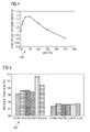
- FIG. 4 is a graph showing the emissivity gain of electrode structures over a conventional electrode structure.
- the spacing of coils leads to a significantly reduced electrode temperature compared to a tightly-wound coil design.
- the emissivity gain begins to diminish.
- the operating temperature on the front area was reduced by 50°K compared to a tight winding electrode structure. The lower temperature resulted in a 50% reduced evaporation rate over a tight winding electrode structure.
- FIG. 5 is a bar graph showing electrode operating temperature measurements of a conventional electrode structure according to electrode 200 of FIG. 2 and an electrode structure according electrode 300, with coil 302 wound at a pitch of 130%.
- Ultra-high pressure mercury lamp test samples were produced with a conventional electrode structure as a first electrode and an example electrode structure as second electrode in the same burner to ensure that both electrodes were operated under identical conditions.
- Each of the lamps are designated in graph 500 by unique hatching patterns, wherein the hatching patterns match for the two electrodes in each lamp.
- the temperatures on the electrode surface were measured with IR pyrometry, excluding areas on the electrode where the IR signal is superposed by plasma radiation.
- Graph 500 shows the electrode temperatures normalized to the average operating temperature of the conventional coil electrodes.
- the average operating temperature of the coils were reduced by more than 2%. Because the tungsten evaporation rate is exponentially related to temperature, the tungsten evaporation rate is halved with an average temperature reduction of approximately 2% .
- lamps with an electrode structure according to one of the examples will last longer at a given temperature or can be operated at higher temperatures over conventional electrode structures.
- manufacturing electrode structures according to an example will typically entail inexpensive modifications to existing electrode manufacturing equipment.
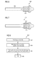
- FIG. 6 shows an electrode structure according to an embodiment.
- Electrode 600 includes plurality of wires 602 attached to electrode head portion 604 in axial sections. Electrode head portion 604 is adjacent to electrode shaft portion 606.
- Plurality of wires 602, if made of tungsten, is expected to have properties similar to coil 302 of FIG. 3 , and thus the optimized pitch of plurality of wires 602 would be around 140% with a groove width of approximately 0.2 mm.
- FIG. 7 shows an alternative electrode structure.
- Electrode 700 includes raised groove features 702 formed as a result of grooving, carving, or etching electrode head portion 704. Groove features 702, if electrode head 204 is made of tungsten, is expected to have properties similar to coil 302 of FIG. 3 , and thus the optimized pitch of groove structure 702 would be around 140% with a groove width of approximately 0.2 mm.
- FIG. 6 is only one possible electrode and many more are within embodiments of the invention.
- Wire applied in a coil, as shown in FIG. 3 could also be applied in concentric sections.
- groove structure 702 of FIG. 7 could also take the form of circumferential slots machined by micro-machining techniques at an optimized pitch, depth, and width. The slots could be applied near the tip and/or elsewhere. Other machined shape variations may include cork screw slots, axial slots, or hole patters.
- FIG. 8 is a flow chart for a method of manufacturing an electrode structure.
- an electrode is provided.
- a wire is attached to the front portion of the electrode.
- the wire is coiled around the electrode head portion at an average pitch of at least 105%.
- method 800 ends.
Landscapes
- Discharge Lamp (AREA)
Claims (5)
- Une électrode configurée de façon à fonctionner dans une lampe à décharge, l'électrode comprenant : une partie tête d'électrode (304) comprenant une pluralité de caractéristiques en saillie (302) fixées à ladite partie tête d'électrode, la pluralité de caractéristiques en saillie étant espacées de façon à augmenter l'émissivité de l'électrode,
caractérisé en ce que la partie tête d'électrode est agencée de sorte que le pas moyen de la pluralité de caractéristiques en saillie se situe (302) entre 124% et 151%, dans lequel par pas moyen on entend la somme du rapport des distances entre des caractéristiques en saillie consécutives sur la largeur des caractéristiques en saillie divisée par le nombre de paires de caractéristiques en saillie,
en ce que la pluralité de caractéristiques en saillie comprend une pluralité de fils (602),
et en ce que chaque fil de la pluralité de fils (602) forme une section axiale fixée à la partie tête d'électrode (304). - L'électrode selon la revendication 1, dans laquelle la pluralité de fils (602) contient du tungstène et la largeur de chaque fil de la pluralité de fils est égale ou inférieure à 0,2 millimètre.
- L'électrode selon la revendication 1, dans laquelle la pluralité de caractéristiques en saillie (302) contient du tungstène.
- Une lampe à décharge possédant deux électrodes, au moins une des électrode étant configurée selon la revendication 1.
- Un procédé de fabrication d'une électrode pour une lampe à décharge, le procédé comprenant : la fourniture d'une électrode configurée de façon à fonctionner dans la lampe à décharge,
la formation de caractéristiques en saillie fixées à ladite partie tête d'électrode (304) de l'électrode, la pluralité de caractéristiques en saillie étant espacées de façon à augmenter l'émissivité de l'électrode, caractérisé en ce que lesdites caractéristiques en saillie sont fixées à ladite partie tête d'électrode à un pas moyen situé entre 124% et 151%, dans lequel par pas moyen on entend la somme du rapport des distances entre des caractéristiques en saillie consécutives sur la largeur des caractéristiques en saillie divisée par le nombre de paires de caractéristiques en saillie,
en ce que la pluralité de caractéristiques en saillie comprend une pluralité de fils (602),
et en ce que chaque fil de la pluralité de fils (602) forme une section axiale fixée à la partie tête d'électrode (304).
Applications Claiming Priority (1)
| Application Number | Priority Date | Filing Date | Title |
|---|---|---|---|
| US12/637,861 US8610350B2 (en) | 2009-12-15 | 2009-12-15 | Electrode structures for discharge lamps |
Publications (2)
| Publication Number | Publication Date |
|---|---|
| EP2337060A1 EP2337060A1 (fr) | 2011-06-22 |
| EP2337060B1 true EP2337060B1 (fr) | 2015-04-22 |
Family
ID=43639901
Family Applications (1)
| Application Number | Title | Priority Date | Filing Date |
|---|---|---|---|
| EP20100190701 Not-in-force EP2337060B1 (fr) | 2009-12-15 | 2010-11-10 | Structures d'électrode pour lampe de décharge |
Country Status (4)
| Country | Link |
|---|---|
| US (1) | US8610350B2 (fr) |
| EP (1) | EP2337060B1 (fr) |
| JP (1) | JP2011129515A (fr) |
| CN (1) | CN102097275B (fr) |
Families Citing this family (4)
| Publication number | Priority date | Publication date | Assignee | Title |
|---|---|---|---|---|
| TWM403094U (en) * | 2010-05-26 | 2011-05-01 | Arclite Optronics Corp | Structure of gas discharge lamp |
| DE102011078472A1 (de) * | 2011-06-30 | 2013-01-03 | Osram Ag | Elektrode und hochdruck-entladungslampe mit dieser elektrode |
| JP2017027765A (ja) * | 2015-07-22 | 2017-02-02 | セイコーエプソン株式会社 | 放電灯、放電灯の製造方法、光源装置、およびプロジェクター |
| JP2020024840A (ja) * | 2018-08-07 | 2020-02-13 | ウシオ電機株式会社 | ショートアーク型放電ランプ |
Citations (1)
| Publication number | Priority date | Publication date | Assignee | Title |
|---|---|---|---|---|
| US2306925A (en) * | 1941-07-29 | 1942-12-29 | Gen Electric | Electrode and its fabrication |
Family Cites Families (17)
| Publication number | Priority date | Publication date | Assignee | Title |
|---|---|---|---|---|
| GB478024A (en) | 1936-11-25 | 1938-01-11 | Gen Electric Co Ltd | Improvements in or relating to thermionic cathodes for high pressure metal vapour discharge devices |
| US2744703A (en) | 1952-09-17 | 1956-05-08 | George M Eames | Train actuated railroad switch |
| BE636192A (fr) | 1962-08-17 | |||
| DE3123442A1 (de) * | 1981-06-12 | 1982-12-30 | Patent-Treuhand-Gesellschaft für elektrische Glühlampen mbH, 8000 München | Gluehwendel fuer eine elektrische lampe und verfahren zur herstellung |
| DE3305468A1 (de) | 1983-02-17 | 1984-08-23 | Egyesült Izzólámpa és Villamossági Részvénytársaság, Budapest | Verfahren zur herstellung von elektroden fuer hochdruck-entladungslampen |
| US4893057A (en) * | 1983-05-10 | 1990-01-09 | North American Philips Corp. | High intensity discharge lamp and electodes for such a lamp |
| JP3327350B2 (ja) | 1993-03-09 | 2002-09-24 | 株式会社渡邊商行 | 放電灯 |
| US5856726A (en) | 1996-03-15 | 1999-01-05 | Osram Sylvania Inc. | Electric lamp with a threaded electrode |
| JPH10154485A (ja) * | 1996-11-22 | 1998-06-09 | Stanley Electric Co Ltd | メタルハライドランプ |
| US5883468A (en) * | 1997-07-24 | 1999-03-16 | Osram Sylvania Inc. | Tungsten halogen lamp with specific fill material, fill pressure, and filament coil parameters |
| DE19757152C2 (de) | 1997-12-20 | 2002-10-31 | Thomas Eggers | Elektrode für Entladungslampen |
| US6492772B1 (en) | 1999-02-10 | 2002-12-10 | Matsushita Electric Industrial Co., Ltd. | High pressure discharge lamp, high pressure discharge lamp electrode, method of producing the high pressure discharge lamp electrode, and illumination device and image display apparatus respectively using the high pressure discharge lamps |
| EP1594156B1 (fr) * | 2004-03-18 | 2013-06-19 | Ushiodenki Kabushiki Kaisha | Dispositif pour le fonctionnement d'une lampe à decharge à haute pression |
| DE102004057906A1 (de) | 2004-11-30 | 2006-06-01 | Patent-Treuhand-Gesellschaft für elektrische Glühlampen mbH | Hochdruckentladungslampe |
| US7176632B2 (en) | 2005-03-15 | 2007-02-13 | Osram Sylvania Inc. | Slotted electrode for high intensity discharge lamp |
| JP2007095665A (ja) | 2005-09-02 | 2007-04-12 | Sony Corp | ショートアーク型高圧放電電極、ショートアーク型高圧放電管、ショートアーク型高圧放電光源装置、及びそれらの各製造方法 |
| US7541726B2 (en) | 2006-05-17 | 2009-06-02 | Osram Sylvania Inc. | Lamp filament |
-
2009
- 2009-12-15 US US12/637,861 patent/US8610350B2/en not_active Expired - Fee Related
-
2010
- 2010-11-10 EP EP20100190701 patent/EP2337060B1/fr not_active Not-in-force
- 2010-12-07 JP JP2010272513A patent/JP2011129515A/ja active Pending
- 2010-12-15 CN CN201010617619.9A patent/CN102097275B/zh not_active Expired - Fee Related
Patent Citations (1)
| Publication number | Priority date | Publication date | Assignee | Title |
|---|---|---|---|---|
| US2306925A (en) * | 1941-07-29 | 1942-12-29 | Gen Electric | Electrode and its fabrication |
Also Published As
| Publication number | Publication date |
|---|---|
| US8610350B2 (en) | 2013-12-17 |
| CN102097275B (zh) | 2016-01-13 |
| US20110140601A1 (en) | 2011-06-16 |
| EP2337060A1 (fr) | 2011-06-22 |
| CN102097275A (zh) | 2011-06-15 |
| JP2011129515A (ja) | 2011-06-30 |
Similar Documents
| Publication | Publication Date | Title |
|---|---|---|
| JP5911179B2 (ja) | 立体形状のセラミックスヒーター | |
| EP2337060B1 (fr) | Structures d'électrode pour lampe de décharge | |
| JP5504095B2 (ja) | 放電ランプ | |
| KR101707682B1 (ko) | 스트립 가열요소 | |
| TWI816958B (zh) | 陶瓷加熱器 | |
| KR20230058534A (ko) | 멀티 존 히터 | |
| JP2003176704A (ja) | タービュレータ付き冷却通路の内側の熱伝達を強化するための方法 | |
| KR20040037262A (ko) | 텅스텐선 및 캐소드 히터 및 내진전구용 필라멘트 | |
| WO2010069438A1 (fr) | Dispositif émetteur à infrarouge pour traitement sous vide à haute température | |
| KR20070100416A (ko) | 길이 방향의 그루브를 포함하는 전극봉 및 석영 전구를갖는 램프 | |
| TWI638380B (zh) | 放電燈管用電極之製造方法及放電燈管 | |
| JP6371275B2 (ja) | 放電ランプ | |
| CN113574652B (zh) | 静电卡盘 | |
| US6871523B2 (en) | Method and apparatus for forming microchannels in a filament wire | |
| US8581493B2 (en) | Ceramic electrode for a high-pressure discharge lamp | |
| CN113574321B (zh) | 火焰检测以及点火装置 | |
| US20140292188A1 (en) | Incandescent bulb, filament, and method for manufacturing filament | |
| JP2009238671A (ja) | ショートアーク型放電ランプ | |
| WO2011043353A1 (fr) | Filament pour canon à électrons et procédé de fabrication de celui-ci | |
| CN103548112A (zh) | 气体放电灯和用于气体放电灯的电极 | |
| WO2007122535A2 (fr) | Procédé de fabrication de tiges d'électrode de tungstène | |
| JP2014232645A (ja) | フィラメントランプ | |
| JP2010153095A (ja) | イオンガン | |
| JP2020198235A (ja) | プラズマ発生装置用部品 | |
| CN209402747U (zh) | 一种电阻连接结构及电阻加热装置 |
Legal Events
| Date | Code | Title | Description |
|---|---|---|---|
| PUAI | Public reference made under article 153(3) epc to a published international application that has entered the european phase |
Free format text: ORIGINAL CODE: 0009012 |
|
| AK | Designated contracting states |
Kind code of ref document: A1 Designated state(s): AL AT BE BG CH CY CZ DE DK EE ES FI FR GB GR HR HU IE IS IT LI LT LU LV MC MK MT NL NO PL PT RO RS SE SI SK SM TR |
|
| AX | Request for extension of the european patent |
Extension state: BA ME |
|
| 17P | Request for examination filed |
Effective date: 20110718 |
|
| 17Q | First examination report despatched |
Effective date: 20120611 |
|
| RAP1 | Party data changed (applicant data changed or rights of an application transferred) |
Owner name: OSRAM AG |
|
| RAP1 | Party data changed (applicant data changed or rights of an application transferred) |
Owner name: OSRAM GMBH |
|
| RAP1 | Party data changed (applicant data changed or rights of an application transferred) |
Owner name: OSRAM GMBH |
|
| GRAP | Despatch of communication of intention to grant a patent |
Free format text: ORIGINAL CODE: EPIDOSNIGR1 |
|
| INTG | Intention to grant announced |
Effective date: 20150203 |
|
| GRAS | Grant fee paid |
Free format text: ORIGINAL CODE: EPIDOSNIGR3 |
|
| GRAA | (expected) grant |
Free format text: ORIGINAL CODE: 0009210 |
|
| AK | Designated contracting states |
Kind code of ref document: B1 Designated state(s): AL AT BE BG CH CY CZ DE DK EE ES FI FR GB GR HR HU IE IS IT LI LT LU LV MC MK MT NL NO PL PT RO RS SE SI SK SM TR |
|
| REG | Reference to a national code |
Ref country code: GB Ref legal event code: FG4D |
|
| REG | Reference to a national code |
Ref country code: CH Ref legal event code: EP |
|
| REG | Reference to a national code |
Ref country code: AT Ref legal event code: REF Ref document number: 723687 Country of ref document: AT Kind code of ref document: T Effective date: 20150515 |
|
| REG | Reference to a national code |
Ref country code: IE Ref legal event code: FG4D |
|
| REG | Reference to a national code |
Ref country code: DE Ref legal event code: R096 Ref document number: 602010024087 Country of ref document: DE Effective date: 20150603 |
|
| REG | Reference to a national code |
Ref country code: NL Ref legal event code: VDEP Effective date: 20150422 |
|
| REG | Reference to a national code |
Ref country code: AT Ref legal event code: MK05 Ref document number: 723687 Country of ref document: AT Kind code of ref document: T Effective date: 20150422 |
|
| REG | Reference to a national code |
Ref country code: LT Ref legal event code: MG4D |
|
| PG25 | Lapsed in a contracting state [announced via postgrant information from national office to epo] |
Ref country code: NL Free format text: LAPSE BECAUSE OF FAILURE TO SUBMIT A TRANSLATION OF THE DESCRIPTION OR TO PAY THE FEE WITHIN THE PRESCRIBED TIME-LIMIT Effective date: 20150422 |
|
| PG25 | Lapsed in a contracting state [announced via postgrant information from national office to epo] |
Ref country code: FI Free format text: LAPSE BECAUSE OF FAILURE TO SUBMIT A TRANSLATION OF THE DESCRIPTION OR TO PAY THE FEE WITHIN THE PRESCRIBED TIME-LIMIT Effective date: 20150422 Ref country code: PT Free format text: LAPSE BECAUSE OF FAILURE TO SUBMIT A TRANSLATION OF THE DESCRIPTION OR TO PAY THE FEE WITHIN THE PRESCRIBED TIME-LIMIT Effective date: 20150824 Ref country code: ES Free format text: LAPSE BECAUSE OF FAILURE TO SUBMIT A TRANSLATION OF THE DESCRIPTION OR TO PAY THE FEE WITHIN THE PRESCRIBED TIME-LIMIT Effective date: 20150422 Ref country code: NO Free format text: LAPSE BECAUSE OF FAILURE TO SUBMIT A TRANSLATION OF THE DESCRIPTION OR TO PAY THE FEE WITHIN THE PRESCRIBED TIME-LIMIT Effective date: 20150722 Ref country code: LT Free format text: LAPSE BECAUSE OF FAILURE TO SUBMIT A TRANSLATION OF THE DESCRIPTION OR TO PAY THE FEE WITHIN THE PRESCRIBED TIME-LIMIT Effective date: 20150422 Ref country code: HR Free format text: LAPSE BECAUSE OF FAILURE TO SUBMIT A TRANSLATION OF THE DESCRIPTION OR TO PAY THE FEE WITHIN THE PRESCRIBED TIME-LIMIT Effective date: 20150422 |
|
| REG | Reference to a national code |
Ref country code: FR Ref legal event code: PLFP Year of fee payment: 6 |
|
| PG25 | Lapsed in a contracting state [announced via postgrant information from national office to epo] |
Ref country code: IS Free format text: LAPSE BECAUSE OF FAILURE TO SUBMIT A TRANSLATION OF THE DESCRIPTION OR TO PAY THE FEE WITHIN THE PRESCRIBED TIME-LIMIT Effective date: 20150822 Ref country code: GR Free format text: LAPSE BECAUSE OF FAILURE TO SUBMIT A TRANSLATION OF THE DESCRIPTION OR TO PAY THE FEE WITHIN THE PRESCRIBED TIME-LIMIT Effective date: 20150723 Ref country code: RS Free format text: LAPSE BECAUSE OF FAILURE TO SUBMIT A TRANSLATION OF THE DESCRIPTION OR TO PAY THE FEE WITHIN THE PRESCRIBED TIME-LIMIT Effective date: 20150422 Ref country code: LV Free format text: LAPSE BECAUSE OF FAILURE TO SUBMIT A TRANSLATION OF THE DESCRIPTION OR TO PAY THE FEE WITHIN THE PRESCRIBED TIME-LIMIT Effective date: 20150422 Ref country code: AT Free format text: LAPSE BECAUSE OF FAILURE TO SUBMIT A TRANSLATION OF THE DESCRIPTION OR TO PAY THE FEE WITHIN THE PRESCRIBED TIME-LIMIT Effective date: 20150422 |
|
| REG | Reference to a national code |
Ref country code: DE Ref legal event code: R097 Ref document number: 602010024087 Country of ref document: DE |
|
| PG25 | Lapsed in a contracting state [announced via postgrant information from national office to epo] |
Ref country code: DK Free format text: LAPSE BECAUSE OF FAILURE TO SUBMIT A TRANSLATION OF THE DESCRIPTION OR TO PAY THE FEE WITHIN THE PRESCRIBED TIME-LIMIT Effective date: 20150422 Ref country code: EE Free format text: LAPSE BECAUSE OF FAILURE TO SUBMIT A TRANSLATION OF THE DESCRIPTION OR TO PAY THE FEE WITHIN THE PRESCRIBED TIME-LIMIT Effective date: 20150422 |
|
| PLBE | No opposition filed within time limit |
Free format text: ORIGINAL CODE: 0009261 |
|
| STAA | Information on the status of an ep patent application or granted ep patent |
Free format text: STATUS: NO OPPOSITION FILED WITHIN TIME LIMIT |
|
| PG25 | Lapsed in a contracting state [announced via postgrant information from national office to epo] |
Ref country code: RO Free format text: LAPSE BECAUSE OF NON-PAYMENT OF DUE FEES Effective date: 20150422 Ref country code: PL Free format text: LAPSE BECAUSE OF FAILURE TO SUBMIT A TRANSLATION OF THE DESCRIPTION OR TO PAY THE FEE WITHIN THE PRESCRIBED TIME-LIMIT Effective date: 20150422 Ref country code: CZ Free format text: LAPSE BECAUSE OF FAILURE TO SUBMIT A TRANSLATION OF THE DESCRIPTION OR TO PAY THE FEE WITHIN THE PRESCRIBED TIME-LIMIT Effective date: 20150422 Ref country code: SK Free format text: LAPSE BECAUSE OF FAILURE TO SUBMIT A TRANSLATION OF THE DESCRIPTION OR TO PAY THE FEE WITHIN THE PRESCRIBED TIME-LIMIT Effective date: 20150422 |
|
| 26N | No opposition filed |
Effective date: 20160125 |
|
| PG25 | Lapsed in a contracting state [announced via postgrant information from national office to epo] |
Ref country code: IT Free format text: LAPSE BECAUSE OF FAILURE TO SUBMIT A TRANSLATION OF THE DESCRIPTION OR TO PAY THE FEE WITHIN THE PRESCRIBED TIME-LIMIT Effective date: 20150422 |
|
| PG25 | Lapsed in a contracting state [announced via postgrant information from national office to epo] |
Ref country code: SI Free format text: LAPSE BECAUSE OF FAILURE TO SUBMIT A TRANSLATION OF THE DESCRIPTION OR TO PAY THE FEE WITHIN THE PRESCRIBED TIME-LIMIT Effective date: 20150422 |
|
| PG25 | Lapsed in a contracting state [announced via postgrant information from national office to epo] |
Ref country code: LU Free format text: LAPSE BECAUSE OF FAILURE TO SUBMIT A TRANSLATION OF THE DESCRIPTION OR TO PAY THE FEE WITHIN THE PRESCRIBED TIME-LIMIT Effective date: 20151110 Ref country code: MC Free format text: LAPSE BECAUSE OF FAILURE TO SUBMIT A TRANSLATION OF THE DESCRIPTION OR TO PAY THE FEE WITHIN THE PRESCRIBED TIME-LIMIT Effective date: 20150422 |
|
| REG | Reference to a national code |
Ref country code: CH Ref legal event code: PL |
|
| GBPC | Gb: european patent ceased through non-payment of renewal fee |
Effective date: 20151110 |
|
| PG25 | Lapsed in a contracting state [announced via postgrant information from national office to epo] |
Ref country code: CH Free format text: LAPSE BECAUSE OF NON-PAYMENT OF DUE FEES Effective date: 20151130 Ref country code: LI Free format text: LAPSE BECAUSE OF NON-PAYMENT OF DUE FEES Effective date: 20151130 |
|
| REG | Reference to a national code |
Ref country code: IE Ref legal event code: MM4A |
|
| PG25 | Lapsed in a contracting state [announced via postgrant information from national office to epo] |
Ref country code: BE Free format text: LAPSE BECAUSE OF FAILURE TO SUBMIT A TRANSLATION OF THE DESCRIPTION OR TO PAY THE FEE WITHIN THE PRESCRIBED TIME-LIMIT Effective date: 20150422 |
|
| PG25 | Lapsed in a contracting state [announced via postgrant information from national office to epo] |
Ref country code: IE Free format text: LAPSE BECAUSE OF NON-PAYMENT OF DUE FEES Effective date: 20151110 Ref country code: GB Free format text: LAPSE BECAUSE OF NON-PAYMENT OF DUE FEES Effective date: 20151110 |
|
| REG | Reference to a national code |
Ref country code: FR Ref legal event code: PLFP Year of fee payment: 7 |
|
| PG25 | Lapsed in a contracting state [announced via postgrant information from national office to epo] |
Ref country code: HU Free format text: LAPSE BECAUSE OF FAILURE TO SUBMIT A TRANSLATION OF THE DESCRIPTION OR TO PAY THE FEE WITHIN THE PRESCRIBED TIME-LIMIT; INVALID AB INITIO Effective date: 20101110 Ref country code: SM Free format text: LAPSE BECAUSE OF FAILURE TO SUBMIT A TRANSLATION OF THE DESCRIPTION OR TO PAY THE FEE WITHIN THE PRESCRIBED TIME-LIMIT Effective date: 20150422 Ref country code: BG Free format text: LAPSE BECAUSE OF FAILURE TO SUBMIT A TRANSLATION OF THE DESCRIPTION OR TO PAY THE FEE WITHIN THE PRESCRIBED TIME-LIMIT Effective date: 20150422 |
|
| PG25 | Lapsed in a contracting state [announced via postgrant information from national office to epo] |
Ref country code: SE Free format text: LAPSE BECAUSE OF FAILURE TO SUBMIT A TRANSLATION OF THE DESCRIPTION OR TO PAY THE FEE WITHIN THE PRESCRIBED TIME-LIMIT Effective date: 20150422 Ref country code: CY Free format text: LAPSE BECAUSE OF FAILURE TO SUBMIT A TRANSLATION OF THE DESCRIPTION OR TO PAY THE FEE WITHIN THE PRESCRIBED TIME-LIMIT Effective date: 20150422 |
|
| PG25 | Lapsed in a contracting state [announced via postgrant information from national office to epo] |
Ref country code: TR Free format text: LAPSE BECAUSE OF FAILURE TO SUBMIT A TRANSLATION OF THE DESCRIPTION OR TO PAY THE FEE WITHIN THE PRESCRIBED TIME-LIMIT Effective date: 20150422 Ref country code: MT Free format text: LAPSE BECAUSE OF FAILURE TO SUBMIT A TRANSLATION OF THE DESCRIPTION OR TO PAY THE FEE WITHIN THE PRESCRIBED TIME-LIMIT Effective date: 20150422 |
|
| REG | Reference to a national code |
Ref country code: FR Ref legal event code: PLFP Year of fee payment: 8 |
|
| PGFP | Annual fee paid to national office [announced via postgrant information from national office to epo] |
Ref country code: FR Payment date: 20171121 Year of fee payment: 8 Ref country code: DE Payment date: 20171121 Year of fee payment: 8 |
|
| PG25 | Lapsed in a contracting state [announced via postgrant information from national office to epo] |
Ref country code: MK Free format text: LAPSE BECAUSE OF FAILURE TO SUBMIT A TRANSLATION OF THE DESCRIPTION OR TO PAY THE FEE WITHIN THE PRESCRIBED TIME-LIMIT Effective date: 20150422 |
|
| PG25 | Lapsed in a contracting state [announced via postgrant information from national office to epo] |
Ref country code: AL Free format text: LAPSE BECAUSE OF FAILURE TO SUBMIT A TRANSLATION OF THE DESCRIPTION OR TO PAY THE FEE WITHIN THE PRESCRIBED TIME-LIMIT Effective date: 20150422 |
|
| REG | Reference to a national code |
Ref country code: DE Ref legal event code: R119 Ref document number: 602010024087 Country of ref document: DE |
|
| PG25 | Lapsed in a contracting state [announced via postgrant information from national office to epo] |
Ref country code: FR Free format text: LAPSE BECAUSE OF NON-PAYMENT OF DUE FEES Effective date: 20181130 Ref country code: DE Free format text: LAPSE BECAUSE OF NON-PAYMENT OF DUE FEES Effective date: 20190601 |