EP2337150B1 - Agencement d'antenne et dispositif de communication radio portable comportant un tel agencement d'antenne - Google Patents
Agencement d'antenne et dispositif de communication radio portable comportant un tel agencement d'antenne Download PDFInfo
- Publication number
- EP2337150B1 EP2337150B1 EP09179830A EP09179830A EP2337150B1 EP 2337150 B1 EP2337150 B1 EP 2337150B1 EP 09179830 A EP09179830 A EP 09179830A EP 09179830 A EP09179830 A EP 09179830A EP 2337150 B1 EP2337150 B1 EP 2337150B1
- Authority
- EP
- European Patent Office
- Prior art keywords
- antenna
- nfc
- gps
- radiating element
- communication device
- Prior art date
- Legal status (The legal status is an assumption and is not a legal conclusion. Google has not performed a legal analysis and makes no representation as to the accuracy of the status listed.)
- Not-in-force
Links
Images

Classifications
-
- H—ELECTRICITY
- H01—ELECTRIC ELEMENTS
- H01Q—ANTENNAS, i.e. RADIO AERIALS
- H01Q1/00—Details of, or arrangements associated with, antennas
- H01Q1/12—Supports; Mounting means
- H01Q1/22—Supports; Mounting means by structural association with other equipment or articles
- H01Q1/24—Supports; Mounting means by structural association with other equipment or articles with receiving set
- H01Q1/241—Supports; Mounting means by structural association with other equipment or articles with receiving set used in mobile communications, e.g. GSM
- H01Q1/242—Supports; Mounting means by structural association with other equipment or articles with receiving set used in mobile communications, e.g. GSM specially adapted for hand-held use
- H01Q1/243—Supports; Mounting means by structural association with other equipment or articles with receiving set used in mobile communications, e.g. GSM specially adapted for hand-held use with built-in antennas
-
- H—ELECTRICITY
- H01—ELECTRIC ELEMENTS
- H01Q—ANTENNAS, i.e. RADIO AERIALS
- H01Q1/00—Details of, or arrangements associated with, antennas
- H01Q1/12—Supports; Mounting means
- H01Q1/22—Supports; Mounting means by structural association with other equipment or articles
- H01Q1/2291—Supports; Mounting means by structural association with other equipment or articles used in Bluetooth® or Wi-Fi® devices of Wireless Local Area Networks [WLAN]
-
- H—ELECTRICITY
- H01—ELECTRIC ELEMENTS
- H01Q—ANTENNAS, i.e. RADIO AERIALS
- H01Q1/00—Details of, or arrangements associated with, antennas
- H01Q1/52—Means for reducing coupling between antennas; Means for reducing coupling between an antenna and another structure
- H01Q1/521—Means for reducing coupling between antennas; Means for reducing coupling between an antenna and another structure reducing the coupling between adjacent antennas
-
- H—ELECTRICITY
- H01—ELECTRIC ELEMENTS
- H01Q—ANTENNAS, i.e. RADIO AERIALS
- H01Q21/00—Antenna arrays or systems
- H01Q21/28—Combinations of substantially independent non-interacting antenna units or systems
-
- H—ELECTRICITY
- H01—ELECTRIC ELEMENTS
- H01Q—ANTENNAS, i.e. RADIO AERIALS
- H01Q21/00—Antenna arrays or systems
- H01Q21/30—Combinations of separate antenna units operating in different wavebands and connected to a common feeder system
Definitions
- the present invention relates generally to antenna arrangements and more particularly to an antenna arrangement for a portable radio communication device providing.
- Internal antennas have been used for some time in portable radio communication devices. There are a number of advantages connected with using internal antennas compared to protruding antennas, of which can be mentioned that they are small and light, making them suitable for applications wherein size and weight are of importance, such as in mobile phones, PDA, portable computer or similar devices.
- the FM radio application is defined as frequencies between 88-108 MHz in most of the world and frequencies between 76-90 MHz in Japan.
- a portable radio communication device is today many times provided with frequency operational coverage for other frequency bands than FM, such as NFC, GSM900, GSM1800, GPS, BT, WLAN, WCDMA and GPS.
- a portable radio communication device has limited space and it is thus desirable, if possible, to add multiple functionality to an antenna arrangement.
- all complementary antennas i.e. non-cellular antennas, are typically allocated to a limited region of a mobile phone. Due to the close proximity of the antennas isolation between the antennas will generally be a problem.
- Document WO 2009/127267 discloses an antenna assembly having a first antenna pattern and a second antenna pattern to be used as a radiating element of an FM Tx antenna or a Near Field Communication antenna.
- Document EP 1 315 238 discloses enhanced electrical isolationg between two antennas of a radio device by substantial degradation in radiation characteristics in operating band of another antenna.
- An object of the present invention is to provide an antenna arrangement comprising an FM antenna, an NFC antenna and a BT antenna for a portable radio communication device, occupying limited space of the portable radio communication device.
- an antenna arrangement for a portable radio communication device comprising an NFC antenna, a BT antenna and an FM radio antenna, wherein the NFC antenna, the BT antenna and the FM radio antenna are positioned in close proximity to each other and are operable simultaneously, is feasible since the NFC antenna is fed through a first decoupling filter and is grounded through a second decoupling filter.
- the decoupling filters each comprises a series inductor having an inductance of about 50-100 nH. In this way BT is decoupled from the NFC antenna.
- the decoupling filters preferably each comprises a further series inductor of about 1000 nH. In this way FM radio is decoupled from the NFC antenna.
- the antenna arrangement also comprises a GPS antenna.
- the GPS antenna and BT antenna preferably have a common radiating element fed through a diplexer.
- the GPS antenna and BT antenna are preferably arranged on opposite sides of the FM antenna.
- the FM radio antenna is preferably arranged between the GPS antenna and the NFC antenna.
- the FM radio antenna is preferably arranged along a top edge of a printed circuit board of the portable radio communication device.
- An advantage of the close proximity of the different antennas is that their radiating elements can all be arranged on a common flex film.
- a portable radio communication device is also provided.
- radiating element is used. It is to be understood that this term is intended to cover electrically conductive elements arranged for receiving and/or transmitting radio signals.
- An antenna arrangement for a portable radio communication device such as a mobile phone or similar device, according to a first embodiment of the present invention will now be described with reference to Figs. 1 and 2 .
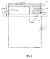
- the antenna arrangement comprises an NFC antenna 1, a BT antenna 2 and an FM antenna 3.
- the radiating elements of the three antennas may be provided completely over, partially over or outside a ground plane means of the portable radio communication device.
- the radiating elements are positioned in an on-ground region of a printed circuit board (PCB), i.e. corresponding to a position over a ground plane means.
- the radiating elements may e.g. be provided as a PIFA, IFA, L-antenna, multi-turn loop antenna, half-loop antenna, or monopole antenna.
- the BT antenna is provided as a quarter-wave monopole
- the FM antenna is provided as an electrically small monopole
- the NFC antenna is provided as an electrically small multi-turn loop.
- the NFC antenna, BT antenna and FM antenna are positioned in close proximity to each other and are operable simultaneously, wherein the NFC antenna is fed through a first decoupling filter and is grounded through a second decoupling filter.
- the FM antenna is fed in a point 7 in the right top corner of the PCB in Fig. 1 .
- the FM antenna has a radiating element extending along essentially the whole length of the top edge of the PCB.
- the NFC antenna is fed in a point 5 in an outer part of the multi-turn loop and grounded in a point 6 in an inner part of the multi-turn loop.
- the opposite feed/ground point is alternatively possible for the NFC antenna.
- the NFC antenna is arranged adjacent to the FM antenna.
- the BT antenna is fed in a point 8, close to the feed point 7 of the FM antenna.
- the radiating element of the BT antenna extends mainly along the right side edge of the PCB and thereafter extends towards the NFC antenna up to minimum distance thereto. In this way optimal position of the FM antenna is achieved and an available spacing is provided between the three antennas for e.g. a speaker or a camera.
- the FM antenna has a radiating element extending along a major portion of the top edge of the PCB, and which continues further down on the PCB.
- the radiating element of the BT antenna extends towards the NFC antenna parallel with the FM antenna and back in a U-shape, positioned upwards of the FM antenna. In this way optimal position of the BT antenna is achieved, and available space is utilized for lengthening of the FM antenna of about 10 mm.
- Each of the BT-decoupling filters for the NFC antenna feeding and grounding preferably comprises a series inductor.
- the series inductor preferably has an inductance of about 50-100 nH, which does not affect the NFC antenna performance.
- the decoupling filters preferably comprises a further series inductor of about 1000 nH, however at some expense of NFC antenna performance.
- the sizes of the radiating elements for the three antennas, for mounting 5 mm above the ground plane means are about as follows: NFC antenna 25x10 mm; FM antenna 40x1 mm; BT antenna 20x1 mm.
- the FM antenna is designed as an electrically small monopole and it is mainly sensitive for electrical fields
- the NFC antenna is designed as an electrically small multi-turn loop and is mainly sensitive for magnetic fields.
- Sufficient isolation is thus achieved between these antennas by a separating distance of at least about 0.5 mm.
- a further series inductor of 1000 nH may be provided in the decoupling filters, however at expense of NFC performance.
- the distance between the radiating element of the FM antenna and the radiating element of the BT antenna should be at least about 2 mm.
- the open end of the BT antenna having a voltage maximum, is preferably arranged as far from the FM antenna as possible, for maximizing the isolation there between.
- the FM antenna preferably comprises a series inductor of about 100 nH blocking BT operation.
- the distance between the radiating element of the NFC antenna and the radiating element of the BT antenna should be at least about 5 mm, with utilization of the BT decoupling inductances mentioned above.
- An advantage by arranging the feed points 7 and 8 of the FM antenna and the BT antenna, respectively, near each other is that an integrated BT and FM engine module can be utilized.
- the BT antenna has been described as one of the three antennas, another type of antenna having an operating frequency significantly higher than FM, such as a GPS antenna, can instead be used.
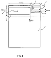
- the antenna arrangement comprises an NFC antenna 1, a BT antenna 2, an FM antenna 3 and a GPS antenna 9.
- the radiating elements of the four antennas may be provided completely over, partially over or outside of a ground plane means of the portable radio communication device.
- the radiating elements are positioned in an on-ground region of a printed circuit board (PCB), i.e. corresponding to a position over a ground plane means.
- the radiating elements may e.g. be provided as a PIFA, IFA, L-antenna, multi-turn loop antenna, half-loop antenna, or monopole antenna.
- the BT antenna and GPS antenna are provided as a quarter-wave monopole
- the FM antenna is provided as an electrically small monopole
- the NFC antenna is provided as an electrically small multi-turn loop.
- the NFC antenna, BT antenna, GPS antenna and FM antenna are positioned in close proximity to each other and are operable simultaneously, wherein the NFC antenna is fed through a first decoupling filter and is grounded through a second decoupling filter.
- the FM antenna is fed in a point 7 at the right edge of the PCB in Fig. 2 .
- the FM antenna has a radiating element extending along a major portion of the top edge of the PCB.
- the NFC antenna is fed in a point 5 in an outer part of the multi-turn loop and grounded in a point 6 in an inner part of the multi-turn loop.
- the opposite feed/ground point is alternatively possible for the NFC antenna.
- the NFC antenna is arranged adjacent to the FM antenna.
- the BT antenna is fed in a point 8, close to the feed point 7 of the FM antenna.
- the radiating element of the BT antenna extends towards the NFC antenna mainly parallel to the FM antenna.
- the GPS antenna is fed in a point 10, close to the feed point 7 of the FM antenna.
- the radiating element of the GPS antenna extends partly along the top edge of the PCB and partly facing upwardly on the top side of the PCB, making the GPS antenna radiating upwards in a speaking position of a mobile phone.
- Each of the decoupling filters for the NFC antenna feeding and grounding comprises a series inductor for BT decoupling.
- the series inductor preferably has an inductance of about 50-100 nH.
- each of the feedings is fed through a decoupling filter.
- the decoupling filters preferably comprises a further series inductor of about 1000 nH, however at some expense of NFC antenna performance.
- the GPS antenna 9 and BT antenna 2 are arranged on opposite sides of the FM antenna 3 assuring good BT-GPS isolation.
- the FM antenna 3 is arranged between the GPS antenna 9 and the NFC antenna 1.
- the sizes of the radiating elements for the four antennas, for mounting 5 mm above the ground plane means are about as follows: NFC antenna 25x10 mm; FM antenna 50x1 mm; BT antenna 20x1 mm; GPS antenna 10x5 mm.
- the distance between the radiating element of the NFC antenna and the radiating element of the FM antenna should be at least about 0.5 mm.
- the distance between the radiating element of the FM antenna and the radiating element of the BT antenna should be at least about 2 mm. However, if the BT antenna is high-pass filtered through e.g. a 1-2 pF capacitor a separating distance of less than 1 mm is sufficient there between.
- the distance between the radiating element of the NFC antenna and the radiating element of the BT antenna should be at least about 5 mm.
- the distance between the radiating element of the NFC antenna and the radiating element of the GPS antenna should be at least about 5 mm.
- the distance between the radiating element of the FM antenna and the radiating element of the GPS antenna should be at least about 2 mm.
- the distance between the radiating element of the GPS antenna and the radiating element of the BT antenna should be at least about 6 mm. However, by arranging the FM antenna between the GPS antenna and the BT antenna efficient use of available space is achieved.
- An advantage by arranging the feed points 7, 8 and 10 of the FM antenna, the BT antenna and the GPS antenna, respectively, near each other is that an integrated FM, BT and GPS engine module can be utilized.
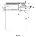
- the antenna arrangement comprises an NFC antenna 1, a BT antenna 11, an FM antenna 3 and a GPS antenna 12.
- the radiating elements of the four antennas may be provided completely over, partially over or outside of a ground plane means of the portable radio communication device.
- the radiating elements are positioned in an on-ground region of a printed circuit board (PCB), i.e. corresponding to a position over a ground plane means.
- the radiating elements may e.g. be provided as a PIFA, IFA, L-antenna, multi-turn loop antenna, half-loop antenna, or monopole antenna.
- the BT antenna, the GPS antenna and the FM antenna are provided as monopole antennas and the NFC antenna is provided as a multi-turn loop antenna.
- the NFC antenna, BT antenna, GPS antenna and FM antenna are positioned in close proximity to each other and are operable simultaneously, wherein the NFC antenna is fed through a first decoupling filter and is grounded through a second decoupling filter.
- the FM antenna is fed in a point 7 at the right edge of the PCB in Fig. 3 .
- the FM antenna has a radiating element extending along a major portion of the top edge of the PCB.
- the NFC antenna is fed in a point 5 in an outer part of the multi-turn loop and grounded in a point 6 in an inner part of the multi-turn loop.
- the opposite feed/ground point is alternatively possible for the NFC antenna.
- the NFC antenna is arranged adjacent to the FM antenna.
- the BT antenna is fed through a BT/GPS diplexer in a point 13, close to the feed point 7 of the FM antenna.
- the GPS antenna is fed through the BT/GPS diplexer in the point 13, in common with the feed point for the BT antenna.
- the radiating element 11 of the BT antenna extends towards the NFC antenna mainly parallel to the FM antenna.
- the radiating element 12 of the GPS antenna extends partly along the top edge of the PCB and partly facing upwardly on the top side of the PCB, making the GPS antenna radiating upwards in a speaking position of a mobile phone.
- the radiating elements 11 and 12 of the BT antenna and the GPS antenna, respectively, are a common radiating element.
- Each of the decoupling filters for the NFC antenna feeding and grounding comprises a series inductor for BT decoupling.
- the series inductor preferably has an inductance of about 50-100 nH.
- each of the feedings is fed through a decoupling filter.
- the decoupling filters preferably comprises a further series inductor of about 1000 nH, however at some expense of NFC performance.
- the FM antenna 3 is arranged between the GPS antenna 12 and the NFC antenna 1 as well as between the BT antenna 11 and the NFC antenna 1.
- the sizes of the radiating elements for the four antennas, for mounting 5 mm above the ground plane means are about as follows: NFC antenna 25x10 mm; FM antenna 50x1 mm; BT antenna and GPS antenna 10x10 mm.
- the distance between the radiating element of the NFC antenna and the radiating element of the FM antenna should be at least about 0.5 mm.
- the distance between the radiating element of the FM antenna and the radiating element of the BT antenna should be at least about 2 mm. However, if the BT antenna is high-pass filtered through e.g. a 1-2 pF capacitor a separating distance of less then 1 mm is sufficient there between.
- the distance between the radiating element of the NFC antenna and the radiating element of the BT antenna should be at least about 5 mm. However, by arranging the FM antenna between the NFC antenna and the BT antenna efficient use of available space is achieved.
- the distance between the radiating element of the NFC antenna and the radiating element of the GPS antenna should be at least about 5 mm.
- by arranging the FM antenna between the GPS antenna and the NFC antenna efficient use of available space is achieved.
- the distance between the radiating element of the FM antenna and the radiating element of the GPS antenna should be at least about 2 mm.
- An advantage by arranging the feed points 7 and 13 of the FM antenna, the BT antenna and GPS antenna, respectively, near each other is that an integrated FM, BT and GPS engine module can be utilized.
Landscapes
- Engineering & Computer Science (AREA)
- Computer Networks & Wireless Communication (AREA)
- Variable-Direction Aerials And Aerial Arrays (AREA)
- Details Of Aerials (AREA)
Claims (9)
- Agencement d'antenne pour un dispositif de communication radio portable, comprenant une antenne NFC (1), une antenne BT (2 ; 11) et une antenne radio FM (3), caractérisé en ce que ladite antenne NFC, ladite antenne BT et ladite antenne radio FM sont positionnées à proximité les unes des autres et sont exploitables simultanément, dans lequel ladite antenne NFC est alimentée (5, 6) par le biais d'un premier filtre de découplage, et est mise à la masse (5, 6) par le biais d'un second filtre de découplage, lesdits filtres de découplage comprenant chacun une bobine d'induction série et ladite bobine d'induction série ayant une inductance d'environ 50 à 100 nH de telle sorte que le mode BT soit découplé de l'antenne NFC et dans lequel ladite antenne NFC et l'antenne radio FM sont agencées l'une adjacente à l'autre.
- Agencement d'antenne selon la revendication 1, dans lequel lesdits filtres de découplage comprennent chacun une autre bobine d'induction série d'environ 1000 nH de telle sorte que le mode radio FM soit découplé de l'antenne NFC.
- Agencement d'antenne selon l'une quelconque des revendications 1 et 2, comprenant une antenne GPS (9 ; 12).
- Agencement d'antenne selon la revendication 3, dans lequel ladite antenne GPS et ladite antenne BT ont un élément rayonnant commun (11, 12) alimenté (13) par un diplexeur.
- Agencement d'antenne selon la revendication 3, dans lequel ladite antenne GPS (9) et ladite antenne BT (2) sont agencées sur des côtés opposés de ladite antenne radio FM (3).
- Agencement d'antenne selon l'une quelconque des revendications 3 à 5, dans lequel ladite antenne radio FM (3) est agencée entre ladite antenne GPS (9 ; 12) et ladite antenne NFC (1).
- Agencement d'antenne selon l'une quelconque des revendications 1 à 6, dans lequel ladite antenne radio FM (3) est agencée le long d'un bord d'une carte à circuit imprimé dudit dispositif de communication radio portable.
- Agencement d'antenne selon l'une quelconque des revendications 1 à 7, dans lequel des points d'alimentation de ladite antenne radio FM et de ladite antenne BT sont agencées à une certaine distance des points d'alimentation de ladite antenne NFC.
- Dispositif de communications radio portable, caractérisé en ce qu'il comprend un agencement d'antenne selon l'une quelconque des revendications 1 à 8.
Priority Applications (4)
| Application Number | Priority Date | Filing Date | Title |
|---|---|---|---|
| EP09179830A EP2337150B1 (fr) | 2009-12-18 | 2009-12-18 | Agencement d'antenne et dispositif de communication radio portable comportant un tel agencement d'antenne |
| PCT/SE2010/051331 WO2011075043A1 (fr) | 2009-12-18 | 2010-12-02 | Agencement d'antenne et dispositif de communication radio portable qui comprend un tel agencement d'antenne |
| CN2010800576088A CN102668238A (zh) | 2009-12-18 | 2010-12-02 | 天线构造和包括这种天线构造的便携无线电通信设备 |
| US13/525,661 US20120249384A1 (en) | 2009-12-18 | 2012-06-18 | Antenna arrangement and a portable radio communication device comprising such an antenna arrangement |
Applications Claiming Priority (1)
| Application Number | Priority Date | Filing Date | Title |
|---|---|---|---|
| EP09179830A EP2337150B1 (fr) | 2009-12-18 | 2009-12-18 | Agencement d'antenne et dispositif de communication radio portable comportant un tel agencement d'antenne |
Publications (2)
| Publication Number | Publication Date |
|---|---|
| EP2337150A1 EP2337150A1 (fr) | 2011-06-22 |
| EP2337150B1 true EP2337150B1 (fr) | 2012-12-05 |
Family
ID=42027961
Family Applications (1)
| Application Number | Title | Priority Date | Filing Date |
|---|---|---|---|
| EP09179830A Not-in-force EP2337150B1 (fr) | 2009-12-18 | 2009-12-18 | Agencement d'antenne et dispositif de communication radio portable comportant un tel agencement d'antenne |
Country Status (4)
| Country | Link |
|---|---|
| US (1) | US20120249384A1 (fr) |
| EP (1) | EP2337150B1 (fr) |
| CN (1) | CN102668238A (fr) |
| WO (1) | WO2011075043A1 (fr) |
Cited By (1)
| Publication number | Priority date | Publication date | Assignee | Title |
|---|---|---|---|---|
| TWI568074B (zh) * | 2014-04-23 | 2017-01-21 | 蘋果公司 | 具有透過顯示器操作之近場天線之電子裝置 |
Families Citing this family (13)
| Publication number | Priority date | Publication date | Assignee | Title |
|---|---|---|---|---|
| US9525293B2 (en) | 2011-12-30 | 2016-12-20 | Makita Corporation | Battery charger having angled wall in battery receiving opening, and battery pack charging system and cordless power tool system including same |
| EP2648193B1 (fr) * | 2012-04-03 | 2015-07-29 | Telefonaktiebolaget L M Ericsson (publ) | Disposition d'inducteur et système à oscillateur commandé par la tension (VCO) |
| US9781496B2 (en) | 2012-10-25 | 2017-10-03 | Milwaukee Electric Tool Corporation | Worksite audio device with wireless interface |
| US9281118B2 (en) | 2012-12-10 | 2016-03-08 | Intel Corporation | Cascaded coils for multi-surface coverage in near field communication |
| DK2863429T3 (en) | 2013-10-16 | 2017-09-04 | ERICSSON TELEFON AB L M (publ) | Adjustable inductor device, transceiver, method and computer program |
| EP3220419B1 (fr) | 2013-10-16 | 2020-07-08 | Telefonaktiebolaget LM Ericsson (publ) | Émetteur-récepteur, récepteur et dispositif de communication ayant un agencement de commutation |
| CN105337028A (zh) * | 2014-07-31 | 2016-02-17 | 展讯通信(上海)有限公司 | 一种天线系统 |
| CN104409869B (zh) * | 2014-11-29 | 2017-10-27 | 青岛歌尔声学科技有限公司 | 一种多合一天线及一种多功能通讯设备 |
| US10468754B2 (en) * | 2017-12-07 | 2019-11-05 | Futurewei Technologies, Inc. | Bifurcated multi-mode ring antenna for a wireless communication device |
| US11251517B2 (en) | 2019-12-26 | 2022-02-15 | Guangdong Oppo Mobile Telecommunications Corp., Ltd. | Antenna assembly and electronic device |
| CN112599975B (zh) * | 2020-12-02 | 2023-02-07 | 维沃移动通信有限公司 | 移动通信设备 |
| CN113467218A (zh) * | 2021-06-30 | 2021-10-01 | 南昌勤胜电子科技有限公司 | 一种智能手表 |
| AT526495A2 (de) * | 2022-08-25 | 2024-03-15 | Siemens Mobility Austria Gmbh | Elektronisches Gerät und Verfahren zur Signalübertragung |
Family Cites Families (13)
| Publication number | Priority date | Publication date | Assignee | Title |
|---|---|---|---|---|
| FI118404B (fi) * | 2001-11-27 | 2007-10-31 | Pulse Finland Oy | Kaksoisantenni ja radiolaite |
| JP4301034B2 (ja) * | 2004-02-26 | 2009-07-22 | パナソニック株式会社 | アンテナが搭載された無線装置 |
| US8428512B2 (en) * | 2005-05-26 | 2013-04-23 | Broadcom Corporation | Method and system for sharing a Bluetooth processor for FM functions |
| JP2007180757A (ja) * | 2005-12-27 | 2007-07-12 | Yokowo Co Ltd | 複数周波数帯用アンテナ |
| US20070145135A1 (en) * | 2005-12-28 | 2007-06-28 | Fabrice Jogand-Coulomb | Methods used in a nested memory system with near field communications capability |
| KR100681929B1 (ko) * | 2005-12-30 | 2007-02-12 | (주)한창시스템 | 이동 통신 단말기용 외장형 장치 및 이를 이용한 nfc통신 방법 |
| US20080081631A1 (en) * | 2006-09-29 | 2008-04-03 | Ahmadreza Rofougaran | Method And System For Integrating An NFC Antenna And A BT/WLAN Antenna |
| US7595759B2 (en) * | 2007-01-04 | 2009-09-29 | Apple Inc. | Handheld electronic devices with isolated antennas |
| US7764932B2 (en) * | 2007-03-14 | 2010-07-27 | Broadcom Corporation | Antenna system for use within a wireless communication device |
| US7683851B2 (en) * | 2007-03-19 | 2010-03-23 | Broadcom Corporation | Method and system for using a single transformer for FM transmit and FM receive functions |
| US7825860B2 (en) * | 2008-04-16 | 2010-11-02 | Sony Ericsson Mobile Communications Ab | Antenna assembly |
| EP2387100B1 (fr) * | 2010-04-29 | 2012-12-05 | Laird Technologies AB | Couvercle métallique pour dispositif de communication radio |
| US8594566B2 (en) * | 2012-01-06 | 2013-11-26 | Blackberry Limited | Mobile wireless communications device with NFC coupling circuit and related methods |
-
2009
- 2009-12-18 EP EP09179830A patent/EP2337150B1/fr not_active Not-in-force
-
2010
- 2010-12-02 CN CN2010800576088A patent/CN102668238A/zh active Pending
- 2010-12-02 WO PCT/SE2010/051331 patent/WO2011075043A1/fr not_active Ceased
-
2012
- 2012-06-18 US US13/525,661 patent/US20120249384A1/en not_active Abandoned
Cited By (1)
| Publication number | Priority date | Publication date | Assignee | Title |
|---|---|---|---|---|
| TWI568074B (zh) * | 2014-04-23 | 2017-01-21 | 蘋果公司 | 具有透過顯示器操作之近場天線之電子裝置 |
Also Published As
| Publication number | Publication date |
|---|---|
| CN102668238A (zh) | 2012-09-12 |
| US20120249384A1 (en) | 2012-10-04 |
| EP2337150A1 (fr) | 2011-06-22 |
| WO2011075043A1 (fr) | 2011-06-23 |
Similar Documents
| Publication | Publication Date | Title |
|---|---|---|
| EP2337150B1 (fr) | Agencement d'antenne et dispositif de communication radio portable comportant un tel agencement d'antenne | |
| CN103178325B (zh) | 松耦合无线电天线设备和方法 | |
| EP2438649B1 (fr) | Communication en champ proche | |
| CN103117452B (zh) | 一种新型lte终端天线 | |
| US8330665B2 (en) | Antenna device and portable radio communication device comprising such antenna device | |
| US7889143B2 (en) | Multiband antenna system and methods | |
| CN103811871B (zh) | 移动装置 | |
| EP2219265A1 (fr) | Dispositif d'antenne, système d'antenne et dispositif de communication radio portable comportant un tel dispositif d'antenne | |
| WO2006011008A1 (fr) | Systeme d'antenne multibande | |
| EP2583350A1 (fr) | Antennes à deux ports avec branches d'antennes séparées comprenant des filtres respectifs | |
| EP2182577A1 (fr) | Dispositif d'antenne, système d'antenne et dispositif de communication radio portable comportant un tel dispositif d'antenne | |
| EP2399322A1 (fr) | Agencement d'antenne, carte de circuit imprimé, dispositif électronique portable et kit de conversion | |
| CN103151601A (zh) | 一种底边槽耦合天线 | |
| EP3352300B1 (fr) | Élément d'antenne et dispositif électronique | |
| KR101633844B1 (ko) | 차량용 다중대역안테나 | |
| KR20090089315A (ko) | 2개의 요소들이 공통 급전선을 공유하게 하는 장치 | |
| EP2234205A1 (fr) | Dispositif d'antenne et dispositif de communication radio portable comportant un tel dispositif d'antenne | |
| CN101573833B (zh) | 包括天线元件和金属部分的装置 | |
| EP2234207A1 (fr) | Dispositif d'antenne et dispositif de communication radio portable comportant un tel dispositif d'antenne | |
| EP2141770A1 (fr) | Dispositif d'antenne et dispositif de communication radio portable comportant un tel dispositif d'antenne | |
| EP2113965A1 (fr) | Antenne multibande à double alimentation et dispositif de communication radio portable comportant une telle antenne | |
| EP2209160B1 (fr) | Dispositif d'antenne, système d'antenne et dispositif de communication radio portable comportant un tel dispositif d'antenne | |
| EP2221914A1 (fr) | Antenne, système d'antenne et dispositif de communication radio portable comportant un tel système d'antenne | |
| EP2166614A1 (fr) | Dispositif d'antenne et dispositif de communication radio portable comportant un tel dispositif d'antenne | |
| EP2493010A1 (fr) | Agencement d'antenne et dispositif de communication radio portable comportant un tel agencement d'antenne |
Legal Events
| Date | Code | Title | Description |
|---|---|---|---|
| PUAI | Public reference made under article 153(3) epc to a published international application that has entered the european phase |
Free format text: ORIGINAL CODE: 0009012 |
|
| AK | Designated contracting states |
Kind code of ref document: A1 Designated state(s): AT BE BG CH CY CZ DE DK EE ES FI FR GB GR HR HU IE IS IT LI LT LU LV MC MK MT NL NO PL PT RO SE SI SK SM TR |
|
| AX | Request for extension of the european patent |
Extension state: AL BA RS |
|
| 17P | Request for examination filed |
Effective date: 20111201 |
|
| GRAP | Despatch of communication of intention to grant a patent |
Free format text: ORIGINAL CODE: EPIDOSNIGR1 |
|
| GRAS | Grant fee paid |
Free format text: ORIGINAL CODE: EPIDOSNIGR3 |
|
| GRAA | (expected) grant |
Free format text: ORIGINAL CODE: 0009210 |
|
| AK | Designated contracting states |
Kind code of ref document: B1 Designated state(s): AT BE BG CH CY CZ DE DK EE ES FI FR GB GR HR HU IE IS IT LI LT LU LV MC MK MT NL NO PL PT RO SE SI SK SM TR |
|
| REG | Reference to a national code |
Ref country code: GB Ref legal event code: FG4D |
|
| REG | Reference to a national code |
Ref country code: CH Ref legal event code: EP |
|
| REG | Reference to a national code |
Ref country code: AT Ref legal event code: REF Ref document number: 587701 Country of ref document: AT Kind code of ref document: T Effective date: 20121215 |
|
| REG | Reference to a national code |
Ref country code: IE Ref legal event code: FG4D |
|
| REG | Reference to a national code |
Ref country code: DE Ref legal event code: R096 Ref document number: 602009011680 Country of ref document: DE Effective date: 20130131 |
|
| REG | Reference to a national code |
Ref country code: AT Ref legal event code: MK05 Ref document number: 587701 Country of ref document: AT Kind code of ref document: T Effective date: 20121205 |
|
| PG25 | Lapsed in a contracting state [announced via postgrant information from national office to epo] |
Ref country code: ES Free format text: LAPSE BECAUSE OF FAILURE TO SUBMIT A TRANSLATION OF THE DESCRIPTION OR TO PAY THE FEE WITHIN THE PRESCRIBED TIME-LIMIT Effective date: 20130316 Ref country code: NO Free format text: LAPSE BECAUSE OF FAILURE TO SUBMIT A TRANSLATION OF THE DESCRIPTION OR TO PAY THE FEE WITHIN THE PRESCRIBED TIME-LIMIT Effective date: 20130305 Ref country code: FI Free format text: LAPSE BECAUSE OF FAILURE TO SUBMIT A TRANSLATION OF THE DESCRIPTION OR TO PAY THE FEE WITHIN THE PRESCRIBED TIME-LIMIT Effective date: 20121205 Ref country code: LT Free format text: LAPSE BECAUSE OF FAILURE TO SUBMIT A TRANSLATION OF THE DESCRIPTION OR TO PAY THE FEE WITHIN THE PRESCRIBED TIME-LIMIT Effective date: 20121205 Ref country code: SE Free format text: LAPSE BECAUSE OF FAILURE TO SUBMIT A TRANSLATION OF THE DESCRIPTION OR TO PAY THE FEE WITHIN THE PRESCRIBED TIME-LIMIT Effective date: 20121205 |
|
| REG | Reference to a national code |
Ref country code: NL Ref legal event code: VDEP Effective date: 20121205 |
|
| REG | Reference to a national code |
Ref country code: LT Ref legal event code: MG4D |
|
| PG25 | Lapsed in a contracting state [announced via postgrant information from national office to epo] |
Ref country code: LV Free format text: LAPSE BECAUSE OF FAILURE TO SUBMIT A TRANSLATION OF THE DESCRIPTION OR TO PAY THE FEE WITHIN THE PRESCRIBED TIME-LIMIT Effective date: 20121205 Ref country code: GR Free format text: LAPSE BECAUSE OF FAILURE TO SUBMIT A TRANSLATION OF THE DESCRIPTION OR TO PAY THE FEE WITHIN THE PRESCRIBED TIME-LIMIT Effective date: 20130306 Ref country code: PL Free format text: LAPSE BECAUSE OF FAILURE TO SUBMIT A TRANSLATION OF THE DESCRIPTION OR TO PAY THE FEE WITHIN THE PRESCRIBED TIME-LIMIT Effective date: 20121205 Ref country code: SI Free format text: LAPSE BECAUSE OF FAILURE TO SUBMIT A TRANSLATION OF THE DESCRIPTION OR TO PAY THE FEE WITHIN THE PRESCRIBED TIME-LIMIT Effective date: 20121205 |
|
| PG25 | Lapsed in a contracting state [announced via postgrant information from national office to epo] |
Ref country code: AT Free format text: LAPSE BECAUSE OF FAILURE TO SUBMIT A TRANSLATION OF THE DESCRIPTION OR TO PAY THE FEE WITHIN THE PRESCRIBED TIME-LIMIT Effective date: 20121205 |
|
| PG25 | Lapsed in a contracting state [announced via postgrant information from national office to epo] |
Ref country code: MC Free format text: LAPSE BECAUSE OF NON-PAYMENT OF DUE FEES Effective date: 20121231 Ref country code: SK Free format text: LAPSE BECAUSE OF FAILURE TO SUBMIT A TRANSLATION OF THE DESCRIPTION OR TO PAY THE FEE WITHIN THE PRESCRIBED TIME-LIMIT Effective date: 20121205 Ref country code: BG Free format text: LAPSE BECAUSE OF FAILURE TO SUBMIT A TRANSLATION OF THE DESCRIPTION OR TO PAY THE FEE WITHIN THE PRESCRIBED TIME-LIMIT Effective date: 20130305 Ref country code: IS Free format text: LAPSE BECAUSE OF FAILURE TO SUBMIT A TRANSLATION OF THE DESCRIPTION OR TO PAY THE FEE WITHIN THE PRESCRIBED TIME-LIMIT Effective date: 20130405 Ref country code: EE Free format text: LAPSE BECAUSE OF FAILURE TO SUBMIT A TRANSLATION OF THE DESCRIPTION OR TO PAY THE FEE WITHIN THE PRESCRIBED TIME-LIMIT Effective date: 20121205 Ref country code: CZ Free format text: LAPSE BECAUSE OF FAILURE TO SUBMIT A TRANSLATION OF THE DESCRIPTION OR TO PAY THE FEE WITHIN THE PRESCRIBED TIME-LIMIT Effective date: 20121205 Ref country code: BE Free format text: LAPSE BECAUSE OF FAILURE TO SUBMIT A TRANSLATION OF THE DESCRIPTION OR TO PAY THE FEE WITHIN THE PRESCRIBED TIME-LIMIT Effective date: 20121205 |
|
| PG25 | Lapsed in a contracting state [announced via postgrant information from national office to epo] |
Ref country code: PT Free format text: LAPSE BECAUSE OF FAILURE TO SUBMIT A TRANSLATION OF THE DESCRIPTION OR TO PAY THE FEE WITHIN THE PRESCRIBED TIME-LIMIT Effective date: 20130405 Ref country code: NL Free format text: LAPSE BECAUSE OF FAILURE TO SUBMIT A TRANSLATION OF THE DESCRIPTION OR TO PAY THE FEE WITHIN THE PRESCRIBED TIME-LIMIT Effective date: 20121205 Ref country code: RO Free format text: LAPSE BECAUSE OF FAILURE TO SUBMIT A TRANSLATION OF THE DESCRIPTION OR TO PAY THE FEE WITHIN THE PRESCRIBED TIME-LIMIT Effective date: 20121205 |
|
| REG | Reference to a national code |
Ref country code: IE Ref legal event code: MM4A |
|
| PLBE | No opposition filed within time limit |
Free format text: ORIGINAL CODE: 0009261 |
|
| STAA | Information on the status of an ep patent application or granted ep patent |
Free format text: STATUS: NO OPPOSITION FILED WITHIN TIME LIMIT |
|
| PG25 | Lapsed in a contracting state [announced via postgrant information from national office to epo] |
Ref country code: IE Free format text: LAPSE BECAUSE OF NON-PAYMENT OF DUE FEES Effective date: 20121218 Ref country code: DK Free format text: LAPSE BECAUSE OF FAILURE TO SUBMIT A TRANSLATION OF THE DESCRIPTION OR TO PAY THE FEE WITHIN THE PRESCRIBED TIME-LIMIT Effective date: 20121205 |
|
| 26N | No opposition filed |
Effective date: 20130906 |
|
| PG25 | Lapsed in a contracting state [announced via postgrant information from national office to epo] |
Ref country code: CY Free format text: LAPSE BECAUSE OF FAILURE TO SUBMIT A TRANSLATION OF THE DESCRIPTION OR TO PAY THE FEE WITHIN THE PRESCRIBED TIME-LIMIT Effective date: 20121205 Ref country code: MT Free format text: LAPSE BECAUSE OF FAILURE TO SUBMIT A TRANSLATION OF THE DESCRIPTION OR TO PAY THE FEE WITHIN THE PRESCRIBED TIME-LIMIT Effective date: 20121205 |
|
| REG | Reference to a national code |
Ref country code: FR Ref legal event code: ST Effective date: 20131108 |
|
| PG25 | Lapsed in a contracting state [announced via postgrant information from national office to epo] |
Ref country code: IT Free format text: LAPSE BECAUSE OF FAILURE TO SUBMIT A TRANSLATION OF THE DESCRIPTION OR TO PAY THE FEE WITHIN THE PRESCRIBED TIME-LIMIT Effective date: 20121205 |
|
| REG | Reference to a national code |
Ref country code: DE Ref legal event code: R097 Ref document number: 602009011680 Country of ref document: DE Effective date: 20130906 |
|
| PG25 | Lapsed in a contracting state [announced via postgrant information from national office to epo] |
Ref country code: HR Free format text: LAPSE BECAUSE OF FAILURE TO SUBMIT A TRANSLATION OF THE DESCRIPTION OR TO PAY THE FEE WITHIN THE PRESCRIBED TIME-LIMIT Effective date: 20130731 Ref country code: FR Free format text: LAPSE BECAUSE OF NON-PAYMENT OF DUE FEES Effective date: 20130205 |
|
| PG25 | Lapsed in a contracting state [announced via postgrant information from national office to epo] |
Ref country code: TR Free format text: LAPSE BECAUSE OF FAILURE TO SUBMIT A TRANSLATION OF THE DESCRIPTION OR TO PAY THE FEE WITHIN THE PRESCRIBED TIME-LIMIT Effective date: 20121205 |
|
| PG25 | Lapsed in a contracting state [announced via postgrant information from national office to epo] |
Ref country code: LU Free format text: LAPSE BECAUSE OF NON-PAYMENT OF DUE FEES Effective date: 20121218 Ref country code: SM Free format text: LAPSE BECAUSE OF FAILURE TO SUBMIT A TRANSLATION OF THE DESCRIPTION OR TO PAY THE FEE WITHIN THE PRESCRIBED TIME-LIMIT Effective date: 20121205 |
|
| REG | Reference to a national code |
Ref country code: DE Ref legal event code: R119 Ref document number: 602009011680 Country of ref document: DE |
|
| PG25 | Lapsed in a contracting state [announced via postgrant information from national office to epo] |
Ref country code: HU Free format text: LAPSE BECAUSE OF FAILURE TO SUBMIT A TRANSLATION OF THE DESCRIPTION OR TO PAY THE FEE WITHIN THE PRESCRIBED TIME-LIMIT Effective date: 20091218 |
|
| REG | Reference to a national code |
Ref country code: CH Ref legal event code: PL |
|
| GBPC | Gb: european patent ceased through non-payment of renewal fee |
Effective date: 20131218 |
|
| PGFP | Annual fee paid to national office [announced via postgrant information from national office to epo] |
Ref country code: DE Payment date: 20130221 Year of fee payment: 4 |
|
| REG | Reference to a national code |
Ref country code: DE Ref legal event code: R119 Ref document number: 602009011680 Country of ref document: DE Effective date: 20140701 |
|
| PG25 | Lapsed in a contracting state [announced via postgrant information from national office to epo] |
Ref country code: CH Free format text: LAPSE BECAUSE OF NON-PAYMENT OF DUE FEES Effective date: 20131231 Ref country code: DE Free format text: LAPSE BECAUSE OF NON-PAYMENT OF DUE FEES Effective date: 20140701 Ref country code: LI Free format text: LAPSE BECAUSE OF NON-PAYMENT OF DUE FEES Effective date: 20131231 |
|
| PG25 | Lapsed in a contracting state [announced via postgrant information from national office to epo] |
Ref country code: GB Free format text: LAPSE BECAUSE OF NON-PAYMENT OF DUE FEES Effective date: 20131218 |
|
| PG25 | Lapsed in a contracting state [announced via postgrant information from national office to epo] |
Ref country code: MK Free format text: LAPSE BECAUSE OF FAILURE TO SUBMIT A TRANSLATION OF THE DESCRIPTION OR TO PAY THE FEE WITHIN THE PRESCRIBED TIME-LIMIT Effective date: 20121205 |