EP2337193B1 - Vorrichtung zur Stromerzeugung und Fernsteuerung für eine solche Vorrichtung - Google Patents
Vorrichtung zur Stromerzeugung und Fernsteuerung für eine solche Vorrichtung Download PDFInfo
- Publication number
- EP2337193B1 EP2337193B1 EP10192314.2A EP10192314A EP2337193B1 EP 2337193 B1 EP2337193 B1 EP 2337193B1 EP 10192314 A EP10192314 A EP 10192314A EP 2337193 B1 EP2337193 B1 EP 2337193B1
- Authority
- EP
- European Patent Office
- Prior art keywords
- flange
- order
- branches
- arm
- movable portion
- Prior art date
- Legal status (The legal status is an assumption and is not a legal conclusion. Google has not performed a legal analysis and makes no representation as to the accuracy of the status listed.)
- Not-in-force
Links
- 238000010248 power generation Methods 0.000 title 1
- 230000005291 magnetic effect Effects 0.000 claims description 74
- 230000004907 flux Effects 0.000 claims description 30
- 238000004873 anchoring Methods 0.000 claims description 10
- 238000009825 accumulation Methods 0.000 claims description 7
- 239000003302 ferromagnetic material Substances 0.000 claims description 5
- 230000002441 reversible effect Effects 0.000 claims description 4
- 230000037452 priming Effects 0.000 claims 15
- 238000006073 displacement reaction Methods 0.000 description 10
- 230000005611 electricity Effects 0.000 description 4
- 238000004146 energy storage Methods 0.000 description 2
- RYGMFSIKBFXOCR-UHFFFAOYSA-N Copper Chemical compound [Cu] RYGMFSIKBFXOCR-UHFFFAOYSA-N 0.000 description 1
- 229910052802 copper Inorganic materials 0.000 description 1
- 239000010949 copper Substances 0.000 description 1
- 230000008878 coupling Effects 0.000 description 1
- 238000010168 coupling process Methods 0.000 description 1
- 238000005859 coupling reaction Methods 0.000 description 1
- 238000007373 indentation Methods 0.000 description 1
- 239000000696 magnetic material Substances 0.000 description 1
- 230000010287 polarization Effects 0.000 description 1
Images




Classifications
-
- H—ELECTRICITY
- H02—GENERATION; CONVERSION OR DISTRIBUTION OF ELECTRIC POWER
- H02K—DYNAMO-ELECTRIC MACHINES
- H02K7/00—Arrangements for handling mechanical energy structurally associated with dynamo-electric machines, e.g. structural association with mechanical driving motors or auxiliary dynamo-electric machines
- H02K7/18—Structural association of electric generators with mechanical driving motors, e.g. with turbines
- H02K7/1807—Rotary generators
- H02K7/1853—Rotary generators driven by intermittent forces
-
- G—PHYSICS
- G08—SIGNALLING
- G08C—TRANSMISSION SYSTEMS FOR MEASURED VALUES, CONTROL OR SIMILAR SIGNALS
- G08C17/00—Arrangements for transmitting signals characterised by the use of a wireless electrical link
-
- H—ELECTRICITY
- H02—GENERATION; CONVERSION OR DISTRIBUTION OF ELECTRIC POWER
- H02K—DYNAMO-ELECTRIC MACHINES
- H02K35/00—Generators with reciprocating, oscillating or vibrating coil system, magnet, armature or other part of the magnetic circuit
- H02K35/02—Generators with reciprocating, oscillating or vibrating coil system, magnet, armature or other part of the magnetic circuit with moving magnets and stationary coil systems
-
- H—ELECTRICITY
- H02—GENERATION; CONVERSION OR DISTRIBUTION OF ELECTRIC POWER
- H02K—DYNAMO-ELECTRIC MACHINES
- H02K7/00—Arrangements for handling mechanical energy structurally associated with dynamo-electric machines, e.g. structural association with mechanical driving motors or auxiliary dynamo-electric machines
- H02K7/18—Structural association of electric generators with mechanical driving motors, e.g. with turbines
- H02K7/1892—Generators with parts oscillating or vibrating about an axis
-
- G—PHYSICS
- G08—SIGNALLING
- G08C—TRANSMISSION SYSTEMS FOR MEASURED VALUES, CONTROL OR SIMILAR SIGNALS
- G08C2201/00—Transmission systems of control signals via wireless link
- G08C2201/10—Power supply of remote control devices
- G08C2201/11—Energy harvesting
- G08C2201/112—Mechanical energy, e.g. vibration, piezoelectric
Definitions
- the invention relates to the field of electricity generating devices and remote controls provided with such generating devices for electrically powering remote control means by the operation of an operating member of said remote control.
- the invention is particularly adapted to small wall remote controls, for example remote controls replacing conventional wall switches to control the opening and closing of switch means that have been deported relative to said remote control.
- the invention also relates to a remote control for remotely controlling remote means, said remote control comprising an operating member and an electrical energy generating device for supplying said remote control.
- the US patent US 6,140,730 discloses a generator comprising two plates in a ferromagnetic material provided with a plurality of arms, said plates being mounted on an axis about which is wound an electric coil, said generator further comprising a movable portion rotatable about said axis and provided with a permanent magnet having a plurality of poles.
- the magnet of the movable portion is disposed relative to the arms of said trays to establish a magnetic field through the coil and whose intensity is variable depending on the rotation of said movable portion. The variation of this magnetic field thus makes it possible to generate at the terminals of the coil an electrical energy depending on the rate of variation of said magnetic field.
- a disadvantage of this generator is that it is not adapted to be activated by means of an operating member of a remote control, in particular an operating member that can occupy two positions for example to control the opening or closing a switch.
- the document DE 10 2008 003596 discloses a device for converting mechanical energy into electrical energy using in particular a monostable structure pivoting about a control axis.
- said device being characterized in that said displacement mechanism comprises control means and arming and driving means coupled to said control means for arming said mechanism by accumulating arming energy generated by at least one part of the stroke of said control means, said arming and driving means cooperating with said movable part to drive it between two stable positions by releasing said arming energy at the end of travel of said control means.
- the first main part comprises a first pair of branches and a second pair of branches respectively forming a first magnetic circuit and a second magnetic circuit
- the second main part comprises a first group of at least two permanent magnets. arranged to respectively close said first and said second magnetic circuit in a first stable position of the movable portion, said permanent magnets of said first group being biased to increase the magnetic flux in the core in said first stable position of the movable portion.
- the branches of the first pair of branches and the branches of the second pair of branches are fixedly mounted on the core and extend radially in directions substantially opposite to the axis of rotation.
- the second main part comprises a second group of at least two permanent magnets arranged to respectively close said first and said second magnetic circuit in a second stable position of the mobile part, said permanent magnets of said second group being biased to increase and reverse the magnetic flux in the core in said second stable position of the moving part.
- the mobile part is essentially constituted by the first main part.
- the arming and driving means comprise a first flange and a second flange rotatably mounted about the axis of rotation, said first flange cooperating with at least one driving branch of the first pair of branches of said movable portion for rotating said movable portion in a first direction, said second flange cooperating with at least one driving branch of the second pair of legs of said movable portion for rotating said movable portion in a second direction opposite said first direction.
- the first flange and the second flange comprise a shoulder provided with a bearing face cooperating with an edge of the drive arm of the first pair of branches respectively and the second pair of branches.
- control means comprise a cocking arm integrally mounted on each flange and extending radially relative to the axis of rotation.
- the arming arm of the first flange and the arming arm of the second flange are designed to rotate respectively the first flange in the second direction and the second flange in the first direction.
- the invention also relates to a remote control for remotely controlling remote means, said remote control comprising an operating member and an electrical energy generating device for supplying said remote control, characterized in that the generating device is as previously described, said device comprising control means coupled to said operating member.
- the electric power generating device 1 comprises a first main part in a ferromagnetic material comprising a core 5, a first pair of branches 11, 12 and a second pair of branches 13, 14. One end of said branches is fixed to the core 5, so as to obtain a magnetic coupling between said branches and said core.
- the figures 1 and 2 only the upper branches 11, 13 of each pair are visible.
- the lower branches 12, 14 of each pair are visible to the figure 3 .
- the branches 11, 12 of the first pair of branches are arranged relative to the core 5 to form a first magnetic circuit having closure ends 15, 16 disposed at the free end of said branches.
- the branches 13, 14 of the second pair of branches are arranged relative to the core 5 to form a second magnetic circuit having ends of closure 17, 18 disposed at the free end of said branches.
- the core 5 is common to the first and second magnetic circuit.
- the closure of the first and / or the second magnetic circuit can be achieved by means of permanent magnets by placing them between the closing ends 15, 16, 17, 18 of a pair of branches 11, 12, 13, 14
- These permanent magnets constitute a second main part of the generating device which is described in more detail below.
- These permanent magnets are polarized to create a magnetic field between the closing ends 15, 16, 17, 18 of the first and / or the second magnetic circuit, a magnetic flux flows in the core 5.
- the generation of electricity is thus achieved by relative movement of the magnetic circuits relative to these permanent magnets to close the first and / or the second magnetic circuit. This relative displacement makes it possible to vary the magnetic flux flowing in the core 5.
- a copper coil 21 wound around a plastic carcass disposed around the core 5 makes it possible to recover the electrical energy obtained by varying the magnetic flux in the core.
- the electricity generating device 1 thus comprises a mechanism for moving a moving part to close the first and / or the second magnetic circuit.
- this mobile part is essentially constituted by the first main part, that is to say the core 5 and the branches 11, 12, 13, 14 magnetically coupled to said core.
- This displacement of the mobile part is, in this case, a rotation around an axis of rotation 20 carrying the core 5.
- the electric power generating device 1 comprises the second main part, mentioned above, said second main part comprising a first group of magnets and a second group of magnets for closing the first and the second magnetic circuit in a first position respectively stable and a second stable position of the movable portion 5, 11, 12, 13, 14.
- the first group of magnets comprises two permanent magnets 31, 32 which are arranged to respectively close the first and the second magnetic circuit in a first position stable of the moving part.
- the permanent magnets 31, 32 of this first group of magnets are biased to increase the magnetic flux in the core in the first stable position of the moving part.
- permanent magnets 31, 32 of the first group of magnets are polarized in the same direction which allows, when the moving part is in the first stable position, to double the magnetic flux in the core 5.
- the second group of magnets also includes two permanent magnets 33, 34 which are arranged to respectively close the first and the second magnetic circuit in a second stable position of the movable part.
- the permanent magnets 33, 34 of the second group of magnets are biased to not only increase, but also invert, the magnetic flux in the core in the second stable position of the movable portion.
- the permanent magnets 33, 34 of the second group of magnets are polarized in the same direction, this direction being opposite to the direction of polarization of the magnets 31, 32 of the first group of magnets.
- This configuration makes it possible, when the moving part is in the second stable position, to double the magnetic flux in the core 5 with respect to a magnetic flux generated by a single magnet and to reverse this magnetic flux in the core 5 with respect to that obtained in the first stable position of the moving part.
- the passage between the first and the second stable position of the movable part, in one direction or the other is accompanied by a inversion of the magnetic flux resulting in a variation of said flux substantially equal to four times the magnetic flux generated by one of the permanent magnets.
- the amount of electrical energy generated in the electric coil 21 is thus increased in the same way.
- the permanent magnets 31, 32, 33, 34 are housed in the openings of a plastic casing formed by two plates 36, 37.
- the coil 21 and its plastic casing is interposed between these two plates 36, 37 and arranged around of the core 5.
- Two sheets 38, 39 made of plastic or other non-magnetic material make it possible to protect the permanent magnets 31, 32, 33, 34 and form gap surfaces between said magnets and the closure ends 15, 16 17, 18 branches 11, 12, 13, 14 forming with the core 5 the two magnetic circuits described above.
- the branches 11, 12 of the first pair of branches and the branches 13, 14 of the second pair of branches are fixedly mounted on the core 5 and extend radially in directions substantially opposed to the axis of rotation 20.
- This arrangement of the branches 11, 12, 13, 14 reduces the size of the generating device, including its dimensions along an axis parallel to the axis of rotation 20.
- the upper branches 11, 13 of each pair of branches are formed in a single piece 41 comprising an opening 43 for fitting said piece 41 in the core 5.
- the lower branches 12, 14 of each pair of branches are formed in a single piece 45 comprising an opening 47 for fitting said piece 45 in the core 5.
- the parts 41, 45 may be called pallets.
- the section of the core 5 coincides with the shape of the openings 43, 47 to allow the branches 11, 12, 13, 14 to be secured to said core.
- the sections of the core 5 and the openings 43, 47 have a symmetry rupture of revolution about the axis 20 so as to ensure a simultaneous rotation of all the branches 11, 12, 13, 14.
- the core 5 and the parts 41, 45 form the mobile part of the generating device 1.
- the branches of one and the same pair of branches extend in substantially parallel directions and are of substantially the same length so that the closing ends of the said branches are screwed together. -a-vis.
- the first and second magnetic circuits formed by the core 5 and the first and second pair of branches respectively can be closed by interposing a permanent magnet between the closing ends of each pair of branches.
- the moving part is essentially constituted by the first main part, that is to say in this case by the magnetic circuits formed by the branches 11, 12, 13, 14 and the core 5.
- the mobile part could be essentially constituted by the second main part, that is to say by the permanent magnets intended to close the magnetic circuits of the first main part.
- the generating device 1 comprises a mechanism for displacing the mobile part 5, 11, 12, 13, 14 around the rotation axis 20 by rotation.
- movement comprises control means and arming and driving means coupled to said control means for establishing an armament of said mechanism.
- the arming and driving means cooperate with the moving part to drive it between the first stable position and the second stable position, in one direction or the other.
- the arming and driving means comprise a first flange 51 and a second flange 52 rotatably mounted about the axis of rotation 20. These flanges can also be called flanges hooking.
- Each flange 51, 52 has a circular opening 55 to be fitted on the core 5. The circular shape of the opening 55 of the flanges 51, 52 allows a rotation of said flanges around the core in one direction or the other.
- Each flange 51, 52 comprises a ring 64 integral with said flange and arranged coaxially around the core 5. The edges of the ring 64 extend in a direction parallel to the axis of rotation.
- An indentation 65 is formed on the edges of the crown 64 of the first and second flanges 51, 52 for respectively receiving a drive arm 11 of the first pair of branches 11, 12 and a drive branch 14 of the second pair branches.
- the first flange 51 cooperates with the drive arm 11 of the first pair of branches 11, 12 of the movable portion to rotate said movable portion in a first direction 53.
- the second flange 52 cooperates, meanwhile, with the drive branch 14 of the second pair of branches of the movable portion for rotating said movable portion in a second direction 54 opposite the first direction 53.
- first flange 51 and the second flange 52 has a shoulder 61 , 62 formed by one of the edges of the notch 65 formed in the ring 64 of said flanges, said shoulder being provided with a bearing face extending parallel to the axis of rotation 20 and cooperating with the edge of the drive arm 11, 14 of respectively the first pair of branches 11, 12 and the second pair of branches 13, 14.
- the arming and driving means are coupled to the control means for arming said mechanism.
- the control means comprise an arming arm 71, 72 mounted integrally on each flange 51, 52 and extending radially relative to the axis of rotation 20.
- the arming arm 71 of the first flange 51 and the arm arming 72 of the second flange 52 are designed to rotate respectively the first flange 51 in the second direction 54 and the second flange 52 in the first direction 53.
- the generator device 1 comprises energy accumulation means cooperating with the arming and driving means 51, 52 for storing the arming energy generated by the movement or displacement of the control means 71, 72.
- This arming energy is generated during at least part of the travel or displacement of the control means 71, 72.
- the energy accumulation means comprise a spring 81 mounted between the arming arms. 71, 72 of the first and second flanges 51, 52.
- the generating device 1 comprises a latch 83 cooperating with the arming and driving means 51, 52 to lock the movable part 5, 11, 12, 13, 14 during arming of the movement mechanism and to unlock said moving part at the end of travel or displacement of the control means 71, 72.
- the lock 83 comprises a lever pivoted about a lock pin 85 parallel and offset relative to the axis of rotation 20, said lever comprising a first latch arm 87 and a second latch arm 89 cooperating with an anchor arm 91, 92 respectively of the first and second flanges 51, 52.
- the latch 83 makes it possible respectively to block the first flange 51 or the second flange 52.
- the latch 83 allows to unlock respectively the first flange 51 or the second flange 52. It follows that the arming energy accumulated by the spring 81 during arming is released and the unblocked flange can cause, thanks to this energy, the moving part from one stable position to another.
- first and second latch arms 87, 89 each have a sliding face 101 extending from a free end of said latch arm to the latch axis 85, said sliding face 101 cooperating with the latch arm 85.
- the first and the second latch arms 87, 89 each comprise a notch 103 disposed between said sliding face 101 and the latch axis 85, said notch 103 cooperating with the end of the latch arm.
- anchoring 91, 92 respectively of the first or second flange 51, 52 for locking said anchor arm and for tilting the latch 83 in a position allowing the unlocking of the anchor arm 92, 91 respectively of the second or the first flange 52, 51.
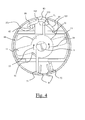
- the operation of the generating device 1 is detailed in the following with reference to the figures 4 and 5 .
- the flange 51 of the generating device has been slightly truncated to show the ring 64 of said flange 51 and the shoulder 61 for rotating the drive arm 11, and therefore the moving part 5, 11, 12, 13, 14, in the first direction 53.
- the movable portion 5, 11, 12, 13, 14 of the generating device is in a first stable position shown in FIG. figure 4 .
- the ends of closures 15, 16, 17, 18 of the branches 11, 12, 13, 14 are closed by the permanent magnets 31, 32 polarized in the same direction.
- the magnetic flux passing through the core, and therefore the electric coil 21 is substantially equal to twice the magnetic flux generated by each magnet.
- the arming arm 72 of the second flange 52 is initially moved to rotate the flange 52 in the direction 53. Only the arming arm 72 and the anchor arm 92 of the second flange 52 are visible on the figures 4 and 5 .
- This rotation drive in the direction 53 can be achieved by means of an operating member cooperating with the arming arms 72.
- This drive in rotation of the second flange 52 in the direction 53 is not accompanied by a rotation of the movable portion 5, 11, 12, 13, 14.
- the recess formed in the ring 64 of the second flange 52 to receive the drive limb 14 of the movable portion is wider than said limb in the same way that the notch in the ring 64 of the first flange 51 to receive the drive limb 11 of the movable portion is wider
- the shoulder 62 of the second flange 52 is supported on an edge of the drive limb 14 allowing only one rotation in a direction 54 opposite to the direction 53.
- the second flange 52 can not not to cause the moving part in the direction 53, and said movable part therefore remains in the first stable position.
- the rotation of the second flange 52 in the direction 53 is accompanied by the rotation of the anchor arm 92 secured to said flange 52. It follows that the end of the anchor arm 92 slides along the side of sliding 101 of the second latch arm 89, which keeps the latch 83 in a position for locking the anchor arm 91 of the first flange 51. The anchor arm 91 of the first puddle 51 is blocked and the rotation said first flange is hampered.
- the end of the anchor arm 92 engages in the notch 103 of the second latch arm 89, which allows to block said anchor arm.
- the latch 83 swings into a position allowing the release of the anchoring arm 91 of the first flange 51. It follows that the rotation of the first flange 51 is no longer impeded and that the spring 81 will be able to release its energy by driving the first flange 51 rotates in the direction 53. This drive in rotation of the first flange 51 in the direction 53 is accompanied by a sudden rotation of the movable portion 5, 11, 12, 13, 14 in the same direction. Indeed, the shoulder 61 of the first flange 51 which is supported on an edge of the drive arm 11 will allow the drive of the movable part in the second stable position.
- the generator device 1 operates in the same way to move from the second stable position represented in FIG. figure 5 at the first stable position represented in figure 4 .
- the generating device 1 is reversible, that is to say that it allows the generation of the same amount of energy when controlling the control means 71, 72 in one direction or the other.
- This rotation of the first flange 51 is accompanied by the rotation of the anchoring arm 91 integral with said flange whose end slides along the sliding face 101 of the first latch arm 87. It follows that the latch 83 is held in a position for locking the anchor arm 92 of the second flange 52.
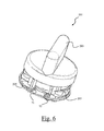
- the remote control 201 remote control remote means not shown, in this case means having two control states, such as a switch having an open position and a closed position.
- the remote control 201 comprises an operating member 203 for remotely actuating the remote means in one or the other of the control states.
- the remote control 201 comprises a generator device 1 as described above, said device being disposed below the control member 203, as is particularly clearly visible on the figure 7 .
- the Generating device 1 comprises control means consisting of two arming arms 71, 72.
- the control means 71, 72 of the generating device are coupled to the operating member 203 by two pins 205, 507.
- pin 205 is supported on the arming arm 71 to drive it in rotation in the direction 53.
- the pin 207 is supported on the arming arm 72 to drive it in rotation in the opposite direction 54.
- the generating device and the remote control according to the invention thus make it possible to generate electrical energy from the displacement of the control means or the operating member coupled to said control means.
- the generator device thus allows autonomous operation of the remote control.
- the use of two magnetic circuits having a common core increases the value of the magnetic flux generated in the core, and the electrical energy generated by variation of said flow is increased.
- the generating device described above has a limited size, particularly as regards its dimension along the axis of rotation, which allows its implementation in remote controls of small thickness, such as wall remotes of traditional form allowing to open or close a remote switch.
- the number of parts used in the generator device is limited, which facilitates assembly and greatly improves its reliability.
Landscapes
- Engineering & Computer Science (AREA)
- Power Engineering (AREA)
- Computer Networks & Wireless Communication (AREA)
- Physics & Mathematics (AREA)
- General Physics & Mathematics (AREA)
- Permanent Magnet Type Synchronous Machine (AREA)
- Electromagnets (AREA)
- Connection Of Motors, Electrical Generators, Mechanical Devices, And The Like (AREA)
Claims (14)
- Vorrichtung zur Erzeugung elektrischer Energie (1), die Folgendes enthält:- einen ersten Hauptteil aus einem ferromagnetischen Material, der mindestens einen Magnetkreis formt, der einen Kern (5) und mindestens ein Paar von Zweigen (11, 12, 13, 14) aufweist, die magnetisch mit dem Kern gekoppelt sind und Enden (15, 16, 17, 18) zum Schließen des mindestens einen Magnetkreises tragen,- einen zweiten Hauptteil, der mindestens einen Dauermagnet (31, 32, 33, 34) aufweist, der angeordnet ist, um den Magnetkreis durch Verschiebung des ersten Hauptteils bezüglich des zweiten Hauptteils zu schließen, wobei der mindestens eine Dauermagnet polarisiert ist, um einen Magnetfluss im Magnetkreis fließen zu lassen, wenn der Magnetkreis geschlossen ist,- einen Verschiebemechanismus durch Drehung eines hauptsächlich aus dem einen oder anderen der Hauptteile bestehenden beweglichen Teils um eine den Kern tragende Drehachse (20), um den mindestens einen Magnetkreis zu schließen, wobei der Verschiebemechanismus Steuereinrichtungen (71, 72) enthält, und- eine Elektrospule (21), die um den Kern gewickelt ist, um die während der Drehung des beweglichen Teils erhaltene elektrische Energie aufzufangen,dadurch gekennzeichnet, dass der Verschiebemechanismus außerdem Spann- und Antriebseinrichtungen (51, 52) enthält, die mit den Steuereinrichtungen (71, 72) gekoppelt sind, um ein Spannen des Mechanismus herzustellen, indem eine Spannenergie gesammelt wird, die von mindestens einem Teil des Hubs der Steuereinrichtungen erzeugt wird, wobei die Spann- und Antriebseinrichtungen mit dem beweglichen Teil zusammenwirken, um ihn zwischen zwei stabilen Stellungen anzutreiben, indem die Spannenergie am Ende des Hubs der Steuereinrichtungen freigesetzt wird.
- Vorrichtung nach Anspruch 1, dadurch gekennzeichnet, dass der erste Hauptteil ein erstes Paar von Zweigen (11, 12) und ein zweites Paar von Zweigen (13, 14) aufweist, die einen ersten Magnetkreis bzw. einen zweiten Magnetkreis formen, und dass der zweite Hauptteil eine erste Gruppe von mindestens zwei Dauermagneten (31, 32) aufweist, die angeordnet sind, um den ersten bzw. den zweiten Magnetkreis in einer ersten stabilen Stellung des beweglichen Teils zu schließen, wobei die Dauermagnete der ersten Gruppe polarisiert sind, um den Magnetfluss im Kern (5) in der ersten stabilen Stellung des beweglichen Teils zu erhöhen.
- Vorrichtung nach Anspruch 2, dadurch gekennzeichnet, dass die Zweige (11, 12) des ersten Paars von Zweigen und die Zweige (13, 14) des zweiten Paars von Zweigen ortsfest auf den Kern (5) montiert sind und sich radial in im Wesentlichen entgegengesetzte Richtungen bezüglich der Drehachse (20) erstrecken.
- Vorrichtung nach Anspruch 3, dadurch gekennzeichnet, dass der zweite Hauptteil eine zweite Gruppe von mindestens zwei Dauermagneten (33, 34) aufweist, die angeordnet sind, um den ersten bzw. den zweiten Magnetkreis in einer zweiten stabilen Stellung des beweglichen Teils zu schließen, wobei die Dauermagnete der zweiten Gruppe polarisiert sind, um den Magnetfluss im Kern (5) in der zweiten stabilen Stellung des beweglichen Teils zu erhöhen und umzukehren.
- Vorrichtung nach einem der Ansprüche 1 bis 4, dadurch gekennzeichnet, dass der bewegliche Teil hauptsächlich aus dem ersten Hauptteil (5, 11, 12, 13, 14) besteht.
- Vorrichtung nach Anspruch 5, dadurch gekennzeichnet, dass die Spann- und Antriebseinrichtungen einen ersten Flansch (51) und einen zweiten Flansch (52) enthalten, die um die Drehachse (20) drehbar montiert sind, wobei der erste Flansch mit mindestens einem Antriebszweig (11) des ersten Paars von Zweigen (11, 12) des beweglichen Teils zusammenwirkt, um den beweglichen Teil in einer ersten Richtung (53) in Drehung zu versetzen, wobei der zweite Flansch mit mindestens einem Antriebszweig (14) des zweiten Paars von Zweigen (13, 14) des beweglichen Teils zusammenwirkt, um den beweglichen Teil in einer zweiten Richtung (54) entgegengesetzt zur ersten Richtung in Drehung zu versetzen.
- Vorrichtung nach Anspruch 6, dadurch gekennzeichnet, dass der erste Flansch (51) und der zweite Flansch (52) eine Schulter (61, 62) aufweisen, die mit einer Auflageseite versehen ist, die mit einem Rand des Antriebszweigs (11, 14) des ersten Paars von Zweigen (11, 12) bzw. des zweiten Paars von Zweigen (13, 14) zusammenwirkt.
- Vorrichtung nach einem der Ansprüche 6 oder 7, dadurch gekennzeichnet, dass die Steuereinrichtungen einen Spannarm (71, 72) enthalten, der auf jeden Flansch (51, 52) fest mit diesem verbunden montiert ist und sich radial bezüglich der Drehachse (20) erstreckt.
- Vorrichtung nach Anspruch 8, dadurch gekennzeichnet, dass der Spannarm (71) des ersten Flanschs (51) und der Spannarm (72) des zweiten Flanschs (52) konzipiert sind, um den ersten Flansch in die zweite Richtung (54) bzw. den zweiten Flansch in die erste Richtung (53) in Drehung zu versetzen.
- Vorrichtung nach einem der Ansprüche 1 bis 9, dadurch gekennzeichnet, dass sie außerdem Folgendes enthält:- Energiesammeleinrichtungen, die mit den Spann- und Antriebseinrichtungen (51, 52) zusammenwirken, um die Spannenergie während des Spannens des Verschiebemechanismus zu speichern, und- einen Riegel, der mit den Spann- und Antriebseinrichtungen zusammenwirkt, um den beweglichen Teil (5, 11, 12, 13, 14) während des Spannens des Verschiebemechanismus zu verriegeln und um den beweglichen Teil am Ende des Hubs der Steuereinrichtungen (71, 72) zu entriegeln.
- Vorrichtung nach Anspruch 10, dadurch gekennzeichnet, dass die Energiesammeleinrichtungen eine Feder (81) enthalten, die zwischen die Spannarme (71, 72) des ersten und des zweiten Flanschs (51, 52) montiert ist.
- Vorrichtung nach einem der Ansprüche 10 oder 11, dadurch gekennzeichnet, dass der Riegel einen Hebel (83) enthält, der um eine Riegelachse (85) schwenkbar montiert ist, wobei der Hebel einen ersten und einen zweiten Riegelarm (87, 89) aufweist, die mit einem Verankerungsarm (91, 92) des ersten bzw. des zweiten Flanschs zusammenwirken, um den ersten Flansch (51) bzw. den zweiten Flansch (52) während des Hubs des Spannarms (72, 71) des zweiten Flanschs (52) bzw. des ersten Flanschs (51) zu blockieren und um den ersten Flansch (51) bzw. den zweiten Flansch (52) am Ende des Hubs des Spannarms (72, 71) des zweiten Flanschs (52) bzw. des ersten Flanschs (51) zu lösen.
- Vorrichtung nach Anspruch 12, dadurch gekennzeichnet, dass der erste und der zweite Riegelarm (87, 89) je Folgendes aufweisen:- eine Gleitseite (101), die sich von einem freien Ende des Riegelarms zur Riegelachse (85) erstreckt, wobei die Gleitseite mit dem Ende des Verankerungsarms (91, 92) des ersten bzw. des zweiten Flanschs (51, 52) zusammenwirkt, um den Riegel (83) in einer Stellung zu halten, die das Blockieren des Verankerungsarms (92, 91) des zweiten bzw. des ersten Flanschs (52, 51) erlaubt, und- eine Kerbe (103), die zwischen der Gleitseite (101) und der Riegelachse (85) angeordnet ist, wobei die Kerbe mit dem Ende des Verankerungsarms (91, 92) des ersten bzw. des zweiten Flanschs (51, 52) zusammenwirkt, um den Verankerungsarm zu blockieren und um den Riegel (83) in eine Stellung zu kippen, die das Lösen des Verankerungsarms (92, 91) des zweiten bzw. ersten Flanschs (52, 51) erlaubt.
- Fernbedienung (201), um verlagerte Einrichtungen fernzusteuern, wobei die Fernbedienung ein Betätigungsorgan (203) und eine Vorrichtung zur Erzeugung elektrischer Energie (1) aufweist, um die Fernbedienung zu versorgen, dadurch gekennzeichnet, dass die Erzeugungsvorrichtung nach einem der vorhergehenden Ansprüche ist, wobei die Vorrichtung Steuereinrichtungen (71, 72) aufweist, die mit dem Betätigungsorgan (203) gekoppelt sind.
Applications Claiming Priority (1)
| Application Number | Priority Date | Filing Date | Title |
|---|---|---|---|
| FR0905865A FR2953659B1 (fr) | 2009-12-04 | 2009-12-04 | Dispositif generateur d'energie electrique et telecommande pourvue d'un tel dispositif |
Publications (2)
| Publication Number | Publication Date |
|---|---|
| EP2337193A1 EP2337193A1 (de) | 2011-06-22 |
| EP2337193B1 true EP2337193B1 (de) | 2013-04-17 |
Family
ID=42315436
Family Applications (1)
| Application Number | Title | Priority Date | Filing Date |
|---|---|---|---|
| EP10192314.2A Not-in-force EP2337193B1 (de) | 2009-12-04 | 2010-11-24 | Vorrichtung zur Stromerzeugung und Fernsteuerung für eine solche Vorrichtung |
Country Status (4)
| Country | Link |
|---|---|
| US (1) | US8624447B2 (de) |
| EP (1) | EP2337193B1 (de) |
| CN (1) | CN102088236B (de) |
| FR (1) | FR2953659B1 (de) |
Cited By (1)
| Publication number | Priority date | Publication date | Assignee | Title |
|---|---|---|---|---|
| EP4738665A1 (de) * | 2024-10-29 | 2026-05-06 | Oodles Systems Limited | Rotierendes selbststromerzeugungsgerät |
Families Citing this family (17)
| Publication number | Priority date | Publication date | Assignee | Title |
|---|---|---|---|---|
| JP5590152B2 (ja) * | 2011-01-12 | 2014-09-17 | ミツミ電機株式会社 | 発電装置及びスイッチ |
| FR2972795B1 (fr) * | 2011-03-15 | 2013-10-11 | Crouzet Automatismes | Capteur inductif de proximite et procede de montage dudit capteur |
| DE102011078932A1 (de) * | 2011-07-11 | 2013-01-17 | Zf Friedrichshafen Ag | Induktionsgenerator |
| WO2013035057A2 (en) * | 2011-09-06 | 2013-03-14 | Kocain Industries S.R.L. | Electric generator and method for producing electrical energy |
| ITMI20111598A1 (it) * | 2011-09-06 | 2013-03-07 | Kocain Ind S R L | Generatore elettrico |
| US9343931B2 (en) | 2012-04-06 | 2016-05-17 | David Deak | Electrical generator with rotational gaussian surface magnet and stationary coil |
| CN103516170A (zh) * | 2012-06-27 | 2014-01-15 | 赵俐娟 | 具有人手开关动作能量收集功能的rf开关控制系统 |
| US9843248B2 (en) * | 2015-06-04 | 2017-12-12 | David Deak, SR. | Rocker action electric generator |
| JP6643697B2 (ja) * | 2015-09-24 | 2020-02-12 | ミツミ電機株式会社 | 電磁変換装置及びアクチュエータ及びポンプ |
| FR3054924B1 (fr) * | 2016-08-04 | 2020-12-04 | Schneider Electric Ind Sas | Partie mobile d'un actionneur electromagnetique pour un contacteur electrique, actionneur comprenant une telle partie et contacteur |
| FR3071678B1 (fr) * | 2017-09-28 | 2019-09-13 | Commissariat A L'energie Atomique Et Aux Energies Alternatives | Convertisseur d'energie electromagnetique |
| US11251007B2 (en) * | 2017-10-30 | 2022-02-15 | Wepower Technologies Llc | Magnetic momentum transfer generator |
| US11742852B2 (en) * | 2017-11-28 | 2023-08-29 | YuanFang LIU | Self-powered wireless switch with micro generator and applications thereof |
| CN111262414B (zh) * | 2018-11-30 | 2022-01-21 | 宁波方太厨具有限公司 | 一种自发电旋钮装置 |
| US11368079B2 (en) | 2019-11-06 | 2022-06-21 | David Deak, SR. | Offset triggered cantilever actuated generator |
| CN115053437A (zh) | 2019-11-21 | 2022-09-13 | 威能科技有限责任公司 | 切向致动的磁动量传输发电机 |
| US11705788B2 (en) * | 2020-09-02 | 2023-07-18 | Michael Robert Maurice | Electromagnetic drive unit with hingeably movable coil around magnet with resilient band holding coil to magnet |
Family Cites Families (11)
| Publication number | Priority date | Publication date | Assignee | Title |
|---|---|---|---|---|
| IT974590B (it) * | 1972-08-12 | 1974-07-10 | Billi Spa | Congegno di comando ad impulsi elettrici per guidafili di mac chine da maglieria e per altri impieghi |
| US6140730A (en) * | 1998-11-16 | 2000-10-31 | General Electric Company | High efficiency electric generator for mechanically powered electronic equipment |
| US6914340B2 (en) * | 2000-12-22 | 2005-07-05 | Freeplay Market Development | Handheld generator |
| DE10315765C5 (de) * | 2003-04-07 | 2021-03-11 | Enocean Gmbh | Verwendung eines elektromagnetischen Energiewandlers |
| DE202005000784U1 (de) * | 2005-01-17 | 2006-05-24 | Hoppe Ag | Vorrichtung zum Erfassen der Position einer Betätigungshandhabe |
| FR2893780A1 (fr) * | 2005-11-22 | 2007-05-25 | Schneider Electric Ind Sas | Dispositif autonome de generation d'energie electrique |
| WO2008019054A2 (en) * | 2006-08-03 | 2008-02-14 | Deak David G | Electromotive device |
| US7498682B2 (en) * | 2007-03-07 | 2009-03-03 | Aaron Patrick Lemieux | Electrical energy generator |
| DE102008003596A1 (de) * | 2008-01-09 | 2009-07-23 | Panasonic Electric Works Europe Ag | Schalteinrichtung und Verfahren zum Einschalten eines Elektrogeräts |
| FR2928501B1 (fr) * | 2008-03-04 | 2011-04-01 | Schneider Electric Ind Sas | Dispositif de generation d'energie a deux parties mobiles |
| DE202008016823U1 (de) * | 2008-12-19 | 2009-03-05 | Selbach, Dirk | Funkrahmenschalter mit Funkmeldung ohne Energieversorgung |
-
2009
- 2009-12-04 FR FR0905865A patent/FR2953659B1/fr not_active Expired - Fee Related
-
2010
- 2010-11-24 EP EP10192314.2A patent/EP2337193B1/de not_active Not-in-force
- 2010-11-30 US US12/956,318 patent/US8624447B2/en not_active Expired - Fee Related
- 2010-12-06 CN CN201010625082.0A patent/CN102088236B/zh not_active Expired - Fee Related
Cited By (1)
| Publication number | Priority date | Publication date | Assignee | Title |
|---|---|---|---|---|
| EP4738665A1 (de) * | 2024-10-29 | 2026-05-06 | Oodles Systems Limited | Rotierendes selbststromerzeugungsgerät |
Also Published As
| Publication number | Publication date |
|---|---|
| US20110133975A1 (en) | 2011-06-09 |
| US8624447B2 (en) | 2014-01-07 |
| EP2337193A1 (de) | 2011-06-22 |
| FR2953659B1 (fr) | 2011-12-23 |
| CN102088236A (zh) | 2011-06-08 |
| FR2953659A1 (fr) | 2011-06-10 |
| CN102088236B (zh) | 2014-06-11 |
Similar Documents
| Publication | Publication Date | Title |
|---|---|---|
| EP2337193A1 (de) | Vorrichtung zur Stromerzeugung und Fernsteuerung für eine solche Vorrichtung | |
| EP2893106B1 (de) | Motorisierte schlagfeste verriegelungsvorrichtung | |
| EP2602804B1 (de) | Betätigungsvorrichtung für die Pole in einer elektrischen Mittelspannungsbetätigungseinrichtung | |
| WO2019002775A1 (fr) | Convertisseur d'energie electromagnetique | |
| EP2765264B1 (de) | Elektronisches Schloss | |
| EP1185995B1 (de) | Steuervorrichtung zum öffnen und/oder zum schliessen, insbesondere für ein schaltgerät wie ein schutzschalter, und ein schutzschalter ausgerüstet mit dieser vorrichtung | |
| FR2953660A1 (fr) | Dispositif generateur d'energie electrique et telecommande comportant un tel dispositif | |
| EP2061059A1 (de) | Steuervorrichtung für ein elektrisches Unterbrechungsgerät und elektrisches Unterbrechungsgerät, das damit ausgestattet ist | |
| FR2923942A1 (fr) | Dispositif de commande d'un appareil de coupure electrique et appareil de coupure electrique le comportant | |
| EP2377139B1 (de) | Vorrichtung zur fernbetätigung und damit versehener schutzschalter | |
| EP2248971A1 (de) | Elektronisches Schloss | |
| FR2982995A1 (fr) | Dispositif de coupure a ecran pour contacteur | |
| EP1925008B1 (de) | Einrichtung zum umschalten eines elektrischen schaltkreises unter verwendung von mindestens zwei permanentmagneten | |
| CA2306675A1 (fr) | Dispositif de commande a trois positions pour appareillage electrique | |
| FR3044162A1 (fr) | Appareil de protection electrique et en particulier disjoncteur electrique moyenne tension | |
| EP1792326B1 (de) | Bistabiler elektromagnetischer aktuator mit integriertem schloss | |
| FR2696497A1 (fr) | Dispositif de fermeture de porte de véhicule. | |
| FR2951316A1 (fr) | Actionneur bistable rotatif | |
| FR2919754A1 (fr) | Relais bistable | |
| FR2968470A1 (fr) | Tiroir electrique enfichable destine a etre monte amovible dans une armoire electrique | |
| FR3082060A1 (fr) | Dispositif et systeme de connexion electrique a prise electrique escamotable | |
| WO2002065497A1 (fr) | Dispositif de manoeuvre bistable en translation d'un axe mobile | |
| EP1836713B1 (de) | Mikrosystem mit integrierter rückhaltemagnetschaltung | |
| EP2442337B1 (de) | Schlüsselkontaktvorrichtung | |
| FR2773908A1 (fr) | Actionneur electromagnetique multi-stable et vehicule automobile equipe de cet actionneur |
Legal Events
| Date | Code | Title | Description |
|---|---|---|---|
| PUAI | Public reference made under article 153(3) epc to a published international application that has entered the european phase |
Free format text: ORIGINAL CODE: 0009012 |
|
| AK | Designated contracting states |
Kind code of ref document: A1 Designated state(s): AL AT BE BG CH CY CZ DE DK EE ES FI FR GB GR HR HU IE IS IT LI LT LU LV MC MK MT NL NO PL PT RO RS SE SI SK SM TR |
|
| AX | Request for extension of the european patent |
Extension state: BA ME |
|
| 17P | Request for examination filed |
Effective date: 20110704 |
|
| RIC1 | Information provided on ipc code assigned before grant |
Ipc: G08C 17/00 20060101ALI20121023BHEP Ipc: H02K 35/02 20060101AFI20121023BHEP Ipc: H02K 7/18 20060101ALI20121023BHEP |
|
| GRAP | Despatch of communication of intention to grant a patent |
Free format text: ORIGINAL CODE: EPIDOSNIGR1 |
|
| GRAS | Grant fee paid |
Free format text: ORIGINAL CODE: EPIDOSNIGR3 |
|
| GRAA | (expected) grant |
Free format text: ORIGINAL CODE: 0009210 |
|
| AK | Designated contracting states |
Kind code of ref document: B1 Designated state(s): AL AT BE BG CH CY CZ DE DK EE ES FI FR GB GR HR HU IE IS IT LI LT LU LV MC MK MT NL NO PL PT RO RS SE SI SK SM TR |
|
| REG | Reference to a national code |
Ref country code: GB Ref legal event code: FG4D Free format text: NOT ENGLISH |
|
| REG | Reference to a national code |
Ref country code: CH Ref legal event code: EP |
|
| REG | Reference to a national code |
Ref country code: IE Ref legal event code: FG4D Free format text: LANGUAGE OF EP DOCUMENT: FRENCH |
|
| REG | Reference to a national code |
Ref country code: AT Ref legal event code: REF Ref document number: 607818 Country of ref document: AT Kind code of ref document: T Effective date: 20130515 |
|
| REG | Reference to a national code |
Ref country code: DE Ref legal event code: R096 Ref document number: 602010006229 Country of ref document: DE Effective date: 20130613 |
|
| REG | Reference to a national code |
Ref country code: AT Ref legal event code: MK05 Ref document number: 607818 Country of ref document: AT Kind code of ref document: T Effective date: 20130417 |
|
| REG | Reference to a national code |
Ref country code: LT Ref legal event code: MG4D |
|
| REG | Reference to a national code |
Ref country code: NL Ref legal event code: VDEP Effective date: 20130417 |
|
| PG25 | Lapsed in a contracting state [announced via postgrant information from national office to epo] |
Ref country code: AT Free format text: LAPSE BECAUSE OF FAILURE TO SUBMIT A TRANSLATION OF THE DESCRIPTION OR TO PAY THE FEE WITHIN THE PRESCRIBED TIME-LIMIT Effective date: 20130417 Ref country code: NO Free format text: LAPSE BECAUSE OF FAILURE TO SUBMIT A TRANSLATION OF THE DESCRIPTION OR TO PAY THE FEE WITHIN THE PRESCRIBED TIME-LIMIT Effective date: 20130717 Ref country code: SE Free format text: LAPSE BECAUSE OF FAILURE TO SUBMIT A TRANSLATION OF THE DESCRIPTION OR TO PAY THE FEE WITHIN THE PRESCRIBED TIME-LIMIT Effective date: 20130417 Ref country code: PT Free format text: LAPSE BECAUSE OF FAILURE TO SUBMIT A TRANSLATION OF THE DESCRIPTION OR TO PAY THE FEE WITHIN THE PRESCRIBED TIME-LIMIT Effective date: 20130819 Ref country code: GR Free format text: LAPSE BECAUSE OF FAILURE TO SUBMIT A TRANSLATION OF THE DESCRIPTION OR TO PAY THE FEE WITHIN THE PRESCRIBED TIME-LIMIT Effective date: 20130718 Ref country code: FI Free format text: LAPSE BECAUSE OF FAILURE TO SUBMIT A TRANSLATION OF THE DESCRIPTION OR TO PAY THE FEE WITHIN THE PRESCRIBED TIME-LIMIT Effective date: 20130417 Ref country code: ES Free format text: LAPSE BECAUSE OF FAILURE TO SUBMIT A TRANSLATION OF THE DESCRIPTION OR TO PAY THE FEE WITHIN THE PRESCRIBED TIME-LIMIT Effective date: 20130728 Ref country code: SI Free format text: LAPSE BECAUSE OF FAILURE TO SUBMIT A TRANSLATION OF THE DESCRIPTION OR TO PAY THE FEE WITHIN THE PRESCRIBED TIME-LIMIT Effective date: 20130417 Ref country code: LT Free format text: LAPSE BECAUSE OF FAILURE TO SUBMIT A TRANSLATION OF THE DESCRIPTION OR TO PAY THE FEE WITHIN THE PRESCRIBED TIME-LIMIT Effective date: 20130417 Ref country code: IS Free format text: LAPSE BECAUSE OF FAILURE TO SUBMIT A TRANSLATION OF THE DESCRIPTION OR TO PAY THE FEE WITHIN THE PRESCRIBED TIME-LIMIT Effective date: 20130817 |
|
| PG25 | Lapsed in a contracting state [announced via postgrant information from national office to epo] |
Ref country code: RS Free format text: LAPSE BECAUSE OF FAILURE TO SUBMIT A TRANSLATION OF THE DESCRIPTION OR TO PAY THE FEE WITHIN THE PRESCRIBED TIME-LIMIT Effective date: 20130417 Ref country code: BG Free format text: LAPSE BECAUSE OF FAILURE TO SUBMIT A TRANSLATION OF THE DESCRIPTION OR TO PAY THE FEE WITHIN THE PRESCRIBED TIME-LIMIT Effective date: 20130717 Ref country code: LV Free format text: LAPSE BECAUSE OF FAILURE TO SUBMIT A TRANSLATION OF THE DESCRIPTION OR TO PAY THE FEE WITHIN THE PRESCRIBED TIME-LIMIT Effective date: 20130417 Ref country code: HR Free format text: LAPSE BECAUSE OF FAILURE TO SUBMIT A TRANSLATION OF THE DESCRIPTION OR TO PAY THE FEE WITHIN THE PRESCRIBED TIME-LIMIT Effective date: 20130417 Ref country code: PL Free format text: LAPSE BECAUSE OF FAILURE TO SUBMIT A TRANSLATION OF THE DESCRIPTION OR TO PAY THE FEE WITHIN THE PRESCRIBED TIME-LIMIT Effective date: 20130417 Ref country code: CY Free format text: LAPSE BECAUSE OF FAILURE TO SUBMIT A TRANSLATION OF THE DESCRIPTION OR TO PAY THE FEE WITHIN THE PRESCRIBED TIME-LIMIT Effective date: 20130417 |
|
| PLBI | Opposition filed |
Free format text: ORIGINAL CODE: 0009260 |
|
| PG25 | Lapsed in a contracting state [announced via postgrant information from national office to epo] |
Ref country code: SK Free format text: LAPSE BECAUSE OF FAILURE TO SUBMIT A TRANSLATION OF THE DESCRIPTION OR TO PAY THE FEE WITHIN THE PRESCRIBED TIME-LIMIT Effective date: 20130417 Ref country code: EE Free format text: LAPSE BECAUSE OF FAILURE TO SUBMIT A TRANSLATION OF THE DESCRIPTION OR TO PAY THE FEE WITHIN THE PRESCRIBED TIME-LIMIT Effective date: 20130417 Ref country code: DK Free format text: LAPSE BECAUSE OF FAILURE TO SUBMIT A TRANSLATION OF THE DESCRIPTION OR TO PAY THE FEE WITHIN THE PRESCRIBED TIME-LIMIT Effective date: 20130417 Ref country code: CZ Free format text: LAPSE BECAUSE OF FAILURE TO SUBMIT A TRANSLATION OF THE DESCRIPTION OR TO PAY THE FEE WITHIN THE PRESCRIBED TIME-LIMIT Effective date: 20130417 |
|
| 26 | Opposition filed |
Opponent name: ENOCEAN GMBH Effective date: 20140117 |
|
| PG25 | Lapsed in a contracting state [announced via postgrant information from national office to epo] |
Ref country code: IT Free format text: LAPSE BECAUSE OF FAILURE TO SUBMIT A TRANSLATION OF THE DESCRIPTION OR TO PAY THE FEE WITHIN THE PRESCRIBED TIME-LIMIT Effective date: 20130417 Ref country code: NL Free format text: LAPSE BECAUSE OF FAILURE TO SUBMIT A TRANSLATION OF THE DESCRIPTION OR TO PAY THE FEE WITHIN THE PRESCRIBED TIME-LIMIT Effective date: 20130417 Ref country code: RO Free format text: LAPSE BECAUSE OF FAILURE TO SUBMIT A TRANSLATION OF THE DESCRIPTION OR TO PAY THE FEE WITHIN THE PRESCRIBED TIME-LIMIT Effective date: 20130417 |
|
| PLAX | Notice of opposition and request to file observation + time limit sent |
Free format text: ORIGINAL CODE: EPIDOSNOBS2 |
|
| REG | Reference to a national code |
Ref country code: DE Ref legal event code: R026 Ref document number: 602010006229 Country of ref document: DE Effective date: 20140117 |
|
| BERE | Be: lapsed |
Owner name: SCHNEIDER ELECTRIC INDUSTRIES SAS Effective date: 20131130 |
|
| PLBB | Reply of patent proprietor to notice(s) of opposition received |
Free format text: ORIGINAL CODE: EPIDOSNOBS3 |
|
| PG25 | Lapsed in a contracting state [announced via postgrant information from national office to epo] |
Ref country code: MC Free format text: LAPSE BECAUSE OF FAILURE TO SUBMIT A TRANSLATION OF THE DESCRIPTION OR TO PAY THE FEE WITHIN THE PRESCRIBED TIME-LIMIT Effective date: 20130417 |
|
| REG | Reference to a national code |
Ref country code: IE Ref legal event code: MM4A |
|
| PG25 | Lapsed in a contracting state [announced via postgrant information from national office to epo] |
Ref country code: BE Free format text: LAPSE BECAUSE OF NON-PAYMENT OF DUE FEES Effective date: 20131130 |
|
| PG25 | Lapsed in a contracting state [announced via postgrant information from national office to epo] |
Ref country code: IE Free format text: LAPSE BECAUSE OF NON-PAYMENT OF DUE FEES Effective date: 20131124 |
|
| PG25 | Lapsed in a contracting state [announced via postgrant information from national office to epo] |
Ref country code: SM Free format text: LAPSE BECAUSE OF FAILURE TO SUBMIT A TRANSLATION OF THE DESCRIPTION OR TO PAY THE FEE WITHIN THE PRESCRIBED TIME-LIMIT Effective date: 20130417 |
|
| PG25 | Lapsed in a contracting state [announced via postgrant information from national office to epo] |
Ref country code: TR Free format text: LAPSE BECAUSE OF FAILURE TO SUBMIT A TRANSLATION OF THE DESCRIPTION OR TO PAY THE FEE WITHIN THE PRESCRIBED TIME-LIMIT Effective date: 20130417 |
|
| REG | Reference to a national code |
Ref country code: CH Ref legal event code: PL |
|
| PLAB | Opposition data, opponent's data or that of the opponent's representative modified |
Free format text: ORIGINAL CODE: 0009299OPPO |
|
| PG25 | Lapsed in a contracting state [announced via postgrant information from national office to epo] |
Ref country code: LI Free format text: LAPSE BECAUSE OF NON-PAYMENT OF DUE FEES Effective date: 20141130 Ref country code: LU Free format text: LAPSE BECAUSE OF NON-PAYMENT OF DUE FEES Effective date: 20131124 Ref country code: MK Free format text: LAPSE BECAUSE OF FAILURE TO SUBMIT A TRANSLATION OF THE DESCRIPTION OR TO PAY THE FEE WITHIN THE PRESCRIBED TIME-LIMIT Effective date: 20130417 Ref country code: CH Free format text: LAPSE BECAUSE OF NON-PAYMENT OF DUE FEES Effective date: 20141130 Ref country code: HU Free format text: LAPSE BECAUSE OF FAILURE TO SUBMIT A TRANSLATION OF THE DESCRIPTION OR TO PAY THE FEE WITHIN THE PRESCRIBED TIME-LIMIT; INVALID AB INITIO Effective date: 20101124 |
|
| R26 | Opposition filed (corrected) |
Opponent name: ENOCEAN GMBH Effective date: 20140117 |
|
| PG25 | Lapsed in a contracting state [announced via postgrant information from national office to epo] |
Ref country code: MT Free format text: LAPSE BECAUSE OF FAILURE TO SUBMIT A TRANSLATION OF THE DESCRIPTION OR TO PAY THE FEE WITHIN THE PRESCRIBED TIME-LIMIT Effective date: 20130417 |
|
| REG | Reference to a national code |
Ref country code: DE Ref legal event code: R100 Ref document number: 602010006229 Country of ref document: DE |
|
| REG | Reference to a national code |
Ref country code: FR Ref legal event code: PLFP Year of fee payment: 6 |
|
| PLCK | Communication despatched that opposition was rejected |
Free format text: ORIGINAL CODE: EPIDOSNREJ1 |
|
| PLBN | Opposition rejected |
Free format text: ORIGINAL CODE: 0009273 |
|
| STAA | Information on the status of an ep patent application or granted ep patent |
Free format text: STATUS: OPPOSITION REJECTED |
|
| 27O | Opposition rejected |
Effective date: 20150918 |
|
| REG | Reference to a national code |
Ref country code: FR Ref legal event code: PLFP Year of fee payment: 7 |
|
| REG | Reference to a national code |
Ref country code: FR Ref legal event code: PLFP Year of fee payment: 8 |
|
| REG | Reference to a national code |
Ref country code: FR Ref legal event code: PLFP Year of fee payment: 9 |
|
| PG25 | Lapsed in a contracting state [announced via postgrant information from national office to epo] |
Ref country code: AL Free format text: LAPSE BECAUSE OF FAILURE TO SUBMIT A TRANSLATION OF THE DESCRIPTION OR TO PAY THE FEE WITHIN THE PRESCRIBED TIME-LIMIT Effective date: 20130417 |
|
| PGFP | Annual fee paid to national office [announced via postgrant information from national office to epo] |
Ref country code: DE Payment date: 20191008 Year of fee payment: 10 |
|
| PGFP | Annual fee paid to national office [announced via postgrant information from national office to epo] |
Ref country code: FR Payment date: 20191009 Year of fee payment: 10 |
|
| PGFP | Annual fee paid to national office [announced via postgrant information from national office to epo] |
Ref country code: GB Payment date: 20191122 Year of fee payment: 10 |
|
| REG | Reference to a national code |
Ref country code: DE Ref legal event code: R119 Ref document number: 602010006229 Country of ref document: DE |
|
| GBPC | Gb: european patent ceased through non-payment of renewal fee |
Effective date: 20201124 |
|
| PG25 | Lapsed in a contracting state [announced via postgrant information from national office to epo] |
Ref country code: FR Free format text: LAPSE BECAUSE OF NON-PAYMENT OF DUE FEES Effective date: 20201130 |
|
| PG25 | Lapsed in a contracting state [announced via postgrant information from national office to epo] |
Ref country code: GB Free format text: LAPSE BECAUSE OF NON-PAYMENT OF DUE FEES Effective date: 20201124 Ref country code: DE Free format text: LAPSE BECAUSE OF NON-PAYMENT OF DUE FEES Effective date: 20210601 |
|
| P01 | Opt-out of the competence of the unified patent court (upc) registered |
Effective date: 20230803 |