EP2337248A2 - Procédé de traitement de signal de diffusion analogue et appareil de réception de signal de diffusion - Google Patents
Procédé de traitement de signal de diffusion analogue et appareil de réception de signal de diffusion Download PDFInfo
- Publication number
- EP2337248A2 EP2337248A2 EP10157603A EP10157603A EP2337248A2 EP 2337248 A2 EP2337248 A2 EP 2337248A2 EP 10157603 A EP10157603 A EP 10157603A EP 10157603 A EP10157603 A EP 10157603A EP 2337248 A2 EP2337248 A2 EP 2337248A2
- Authority
- EP
- European Patent Office
- Prior art keywords
- broadcasting
- signal
- broadcasting signal
- vertical synchronization
- broadcasting system
- Prior art date
- Legal status (The legal status is an assumption and is not a legal conclusion. Google has not performed a legal analysis and makes no representation as to the accuracy of the status listed.)
- Withdrawn
Links
Images


Classifications
-
- H—ELECTRICITY
- H04—ELECTRIC COMMUNICATION TECHNIQUE
- H04H—BROADCAST COMMUNICATION
- H04H60/00—Arrangements for broadcast applications with a direct linking to broadcast information or broadcast space-time; Broadcast-related systems
-
- H—ELECTRICITY
- H04—ELECTRIC COMMUNICATION TECHNIQUE
- H04N—PICTORIAL COMMUNICATION, e.g. TELEVISION
- H04N5/00—Details of television systems
- H04N5/44—Receiver circuitry for the reception of television signals according to analogue transmission standards
-
- H—ELECTRICITY
- H04—ELECTRIC COMMUNICATION TECHNIQUE
- H04H—BROADCAST COMMUNICATION
- H04H40/00—Arrangements specially adapted for receiving broadcast information
- H04H40/18—Arrangements characterised by circuits or components specially adapted for receiving
-
- H—ELECTRICITY
- H04—ELECTRIC COMMUNICATION TECHNIQUE
- H04N—PICTORIAL COMMUNICATION, e.g. TELEVISION
- H04N7/00—Television systems
- H04N7/015—High-definition television systems
Definitions
- the present invention relates to a method and apparatus for processing an analog broadcasting signal in an analog broadcasting signal receiving apparatus.
- TVs analog televisions
- NSC national television system commission
- SECAM sequentiel line a memoire
- PAL phase alternation by line
- each of the systems is specifically divided into a BG, DK, I, L, or MN system according to an intermediate frequency (IF) transmission standard.
- IF intermediate frequency
- TVs generally processing an analog broadcasting signal need to perform an additional channel scan to detect L system channels when performing a channel search.
- FIG. 1 is a block diagram for describing processing of a broadcasting signal received in a general broadcasting signal receiving apparatus.
- a received radio frequency (RF) broadcasting signal is frequency-converted to output an IF broadcasting signal.
- RF radio frequency
- the IF broadcasting signal is filtered and demodulated to output a baseband broadcasting signal.
- the baseband broadcasting signal is decoded and output.
- the decoded broadcasting signal is displayed.
- a video processor performing the block 120 sets a video polarity as negative, scans all of the channels, and changes the video polarity to positive, and then repeats the same channel scan. Accordingly, general analog TVs require a long channel search time.
- the present invention provides a method and apparatus for effectively processing an analog broadcasting signal in an analog broadcasting signal receiving apparatus.
- a method of processing an analog broadcasting signal performed by a broadcasting signal receiving apparatus, the method including; determining broadcasting system modes of all broadcasting channels existing in a predetermined frequency band, on the basis of an intermediate frequency (IF) broadcasting signal that is frequency-converted from a radio frequency (RF) broadcasting signal; generating broadcasting system mode information showing the broadcasting system modes with respect to the broadcasting channels according to a result of the determining; and decoding a baseband broadcasting signal with reference to the generated broadcasting system mode information.
- IF intermediate frequency
- RF radio frequency
- the broadcasting system mode information may show that a vertical synchronization signal having a positive polarity is included in the IF broadcasting signal, a vertical synchronization signal having a negative polarity is included in the IF broadcasting signal, or a vertical synchronization signal is not included in the IF broadcasting signal.
- the determining of the broadcasting system modes may include determining the broadcasting system modes with respect to the broadcasting channels according to a polarity of the vertical synchronization signal included in the IF broadcasting signal.
- the determining of the broadcasting system modes may include determining that when the vertical synchronization signal included in the IF broadcasting signal is negative, the broadcasting system mode is an L type.
- the method of processing the analog broadcasting signal may further include generating a channel map with respect to the broadcasting channels by using the broadcasting system mode information and additional information that is obtained as a result of the decoding.
- a broadcasting signal receiving apparatus for processing an analog broadcasting signal, the apparatus including: a determining unit for determining broadcasting system modes of all broadcasting channels existing in a predetermined frequency band, on the basis of an IF broadcasting signal that is frequency-converted from an RF broadcasting signal; a generating unit for generating broadcasting system mode information showing the broadcasting system modes with respect to the broadcasting channels according to a result of the determining; and a decoding unit for decoding a baseband broadcasting signal with reference to the generated broadcasting system mode information.
- the broadcasting system mode information may show that a vertical synchronization signal having a positive polarity is included in the IF broadcasting signal, a vertical synchronization signal having a negative polarity is included in the IF broadcasting signal, or a vertical synchronization signal is not included in the IF broadcasting signal.
- the determining unit may determine the broadcasting system modes with respect to the broadcasting channels according to a polarity of the vertical synchronization signal included in the IF broadcasting signal.
- the determining unit may determine that when the vertical synchronization signal included in the IF broadcasting signal is negative, the broadcasting system mode is an L type.
- the apparatus may further include a channel map generating unit generating a channel map with respect to the broadcasting channels by using the broadcasting system mode information and additional information that is obtained as a result of the decoding.
- a computer readable recording medium having embodied thereon a computer program for executing the method of processing the analog broadcasting signal.
- FIG. 2 is a flowchart for describing processing of a received broadcasting signal, according to an embodiment of the present invention.
- a broadcasting signal receiving apparatus receives a radio frequency (RF) broadcasting signal.
- RF radio frequency
- the received RF broadcasting signal is frequency-converted into an intermediate frequency (IF) broadcasting signal.
- IF intermediate frequency
- the broadcasting signal receiving apparatus determines broadcasting system modes of all broadcasting channels by using the IF broadcasting signal.
- the broadcasting signal receiving apparatus In operation 240, the broadcasting signal receiving apparatus generates broadcasting system mode information that shows each broadcasting system mode of all the broadcasting channels according to a determination result of operation 230.
- a video processor for processing a baseband broadcasting signal scans the broadcasting channels with reference to the broadcasting system mode information and decodes a detected broadcasting signal.
- a channel map is generated by using the broadcasting system mode information and additional information.
- the additional information denotes metadata related to a broadcasting channel, such as broadcasting program information or broadcasting station information, and is obtained by decoding a broadcasting signal.
- the channel map is information in which the broadcasting signal receiving apparatus searches for a channel having a broadcasting signal through a channel search process and then maps information related to the channel with a channel number, and is used to rapidly tune a channel when a user changes channel.
- a broadcasting system mode is determined from the IF broadcasting signal, a channel scan is performed with respect to the baseband broadcasting signal according to the determination result, and thus, the time to perform the channel scan is shortened compared to prior technology.
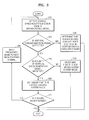
- FIG. 3 is a flowchart for describing a process of determining broadcasting system modes of all broadcasting channels, according to an embodiment of the present invention.
- a broadcasting signal receiving apparatus detects a vertical synchronization signal from an IF broadcasting signal.
- the broadcasting signal receiving apparatus determines whether the vertical synchronization signal is detected from the IF broadcasting signal.
- operation 340 if the vertical synchronization signal is detected in operation 320, it is determined whether a polarity of the detected vertical synchronization signal is negative.
- a polarity of the detected vertical synchronization signal is determined to be positive in operation 340, it is determined that the broadcasting channel of the corresponding frequency band is not an L broadcasting system mode.
- operation 360 if the polarity of the vertical synchronization signal is determined to be negative in operation 340, it is determined that the broadcasting channel of the corresponding frequency band is the L broadcasting system mode.
- operation 370 it is determined whether scan of all broadcasting channels existing in a predetermined frequency band is finished.
- operation 380 if scanning of all the broadcasting channels is determined to be not finished in operation 370, the frequency band is shifted to the next broadcasting channel, and operations 320 through 370 are repeated.
- FIG. 4A is a graph illustrating a vertical synchronization signal pattern of a sequentiel line a memoire (SECAM)-L broadcasting signal, according to an embodiment of the present invention.
- SECAM sequentiel line a memoire
- FIG. 4B is a graph illustrating a vertical synchronization signal pattern of a phase alternation by line (PAL)-BG broadcasting signal, according to an embodiment of the present invention. As illustrated in FIG. 4B , other broadcasting systems except for the L broadcasting system use a vertical synchronization signal having a positive polarity.
- PAL phase alternation by line
- a video processor since a broadcasting system mode is decided by determining a polarity of the vertical synchronization signal from an IF broadcasting signal, a video processor does not need to perform a channel scan twice in order to determine the broadcasting system mode.
- FIG. 5 is a block diagram illustrating a structure of a broadcasting signal receiving apparatus, according to an embodiment of the present invention.
- a broadcasting signal receiving apparatus 500 includes an RF processor 510, an IF demodulator 520, and an audio/video (A/V) processor 530.
- the RF processor 510 frequency-converts a received RF broadcasting signal to output an IF broadcasting signal.
- the IF demodulator 520 processes the IF broadcasting signal that is output from the RF processor 510 and outputs a baseband broadcasting signal. As illustrated in FIG. 5 , the IF demodulator 520 includes an auto gain control (AGC) 521, a filter 522, a determining unit 523, and a generating unit 524.
- AGC auto gain control
- the AGC 521 allows the output signal to have a constant voltage by automatically adjusting a gain according to changes of the input IF broadcasting signal.
- the filter 522 lowpass filters the signal that is output through the AGC 521 to output the baseband broadcasting signal.
- the determining unit 523 determines broadcasting system modes of all broadcasting channels existing in a predetermined frequency band from the IF broadcasting signal that is output from the RF processor 510. As described above, when a polarity of the vertical synchronization signal included in the IF broadcasting signal is negative, the determining unit 523 determines that the broadcasting system mode of the corresponding broadcasting channel is an L type. On the other hand, when a polarity of the vertical synchronization signal included in the IF broadcasting signal is positive, the determining unit 523 determines that the broadcasting system mode of the corresponding broadcasting channel is not an L type.
- the determining unit 523 determines that the broadcasting channel does not exist in the corresponding frequency band.
- the generating unit 524 generates broadcasting system mode information showing broadcasting system modes with respect to broadcasting channels according to the determination result of the determining unit 523.
- the broadcasting system mode information may show three states. For example, it may show that a vertical synchronization signal having a negative polarity is included in the IF broadcasting signal, a vertical synchronization signal having a positive polarity is included in the IF broadcasting signal, or a vertical synchronization signal is included in the IF broadcasting signal.
- the three states may show that the broadcasting system mode of the corresponding broadcasting channel is an L type or not an L type, or may show that the broadcasting channel does not exist in the corresponding frequency band.
- the IF demodulator 520 includes the determining unit 523 and the generating unit 524, but may include different chips according to an implementation method.
- the A/V processor 530 is a module that processes baseband audio and video signals. As illustrated in FIG. 5 , the A/V processor 530 includes a decoding unit 531, a controlling unit 532, and a channel map generating unit 533.
- the decoding unit 531 decodes the baseband broadcasting signal using the broadcasting system mode information generated in the generating unit 524. That is, the decoding unit 531 may know polarities of video signals of all broadcasting channels with reference to broadcasting system mode information, without directly scanning the video signals having positive and negative polarities.
- the channel map generating unit 533 generates a channel map by using the additional information obtained by decoding the broadcasting signal in the decoding unit 531 and the broadcasting system mode information generated in the generating unit 524.
- the additional information denotes metadata related to the broadcasting channel, such as broadcasting program information or broadcasting station information.
- the channel map denotes information in which the broadcasting signal receiving apparatus 500 searches for all the broadcasting channels and then maps information related to the broadcasting channels with a channel number, and is used to rapidly tune a channel when a user changes the channel.
- the controlling unit 532 controls the A/V processor 530 so that the channel map generating unit 533 functions by using the broadcasting system mode information.
- the A/V processor 530 includes the channel map generating unit 533, but may include a different chip according to an implementation method.
- a channel search process may be finished by performing just one channel scan.
- the present invention can also be embodied as computer readable codes on a computer readable recording medium.
- the computer readable recording medium is any data storage device that can store data which can be thereafter read by a computer system. Examples of the computer readable recording medium include read-only memory (ROM), random-access memory (RAM), CD-ROMs, magnetic tapes, floppy disks, optical data storage devices, and etc.
- the computer readable recording medium can also be distributed over network coupled computer systems so that the computer readable code is stored and executed in a distributed fashion.
Landscapes
- Engineering & Computer Science (AREA)
- Signal Processing (AREA)
- Multimedia (AREA)
- Two-Way Televisions, Distribution Of Moving Picture Or The Like (AREA)
- Circuits Of Receivers In General (AREA)
Applications Claiming Priority (1)
| Application Number | Priority Date | Filing Date | Title |
|---|---|---|---|
| KR1020090105979A KR20110049119A (ko) | 2009-11-04 | 2009-11-04 | 아날로그 방송 신호를 처리하는 방법 및 이를 위한 방송 수신 장치 |
Publications (2)
| Publication Number | Publication Date |
|---|---|
| EP2337248A2 true EP2337248A2 (fr) | 2011-06-22 |
| EP2337248A3 EP2337248A3 (fr) | 2012-10-10 |
Family
ID=42646464
Family Applications (1)
| Application Number | Title | Priority Date | Filing Date |
|---|---|---|---|
| EP10157603A Withdrawn EP2337248A3 (fr) | 2009-11-04 | 2010-03-24 | Procédé de traitement de signal de diffusion analogue et appareil de réception de signal de diffusion |
Country Status (3)
| Country | Link |
|---|---|
| EP (1) | EP2337248A3 (fr) |
| KR (1) | KR20110049119A (fr) |
| CN (1) | CN102055542A (fr) |
Family Cites Families (4)
| Publication number | Priority date | Publication date | Assignee | Title |
|---|---|---|---|---|
| JP2969242B2 (ja) * | 1993-11-30 | 1999-11-02 | 赤井電機株式会社 | テレビ受信装置 |
| JP2002165150A (ja) * | 2000-11-28 | 2002-06-07 | Mitsubishi Electric Corp | 受信装置 |
| GB0221296D0 (en) * | 2002-09-13 | 2002-10-23 | British Broadcasting Corp | Improved digital broadcast receiver |
| JP4720160B2 (ja) * | 2004-11-30 | 2011-07-13 | 船井電機株式会社 | 放送受信装置 |
-
2009
- 2009-11-04 KR KR1020090105979A patent/KR20110049119A/ko not_active Withdrawn
-
2010
- 2010-03-24 EP EP10157603A patent/EP2337248A3/fr not_active Withdrawn
- 2010-03-25 CN CN2010101476939A patent/CN102055542A/zh active Pending
Non-Patent Citations (1)
| Title |
|---|
| None |
Also Published As
| Publication number | Publication date |
|---|---|
| CN102055542A (zh) | 2011-05-11 |
| KR20110049119A (ko) | 2011-05-12 |
| EP2337248A3 (fr) | 2012-10-10 |
Similar Documents
| Publication | Publication Date | Title |
|---|---|---|
| JP3920575B2 (ja) | デジタル放送受信機におけるチャンネル情報登録処理方法 | |
| US7508459B2 (en) | Method and apparatus for performing channel detection | |
| JP2006033630A (ja) | ディジタルテレビジョン放送信号受信装置 | |
| WO2001093570A1 (fr) | Appareil selecteur de canaux | |
| EP2337248A2 (fr) | Procédé de traitement de signal de diffusion analogue et appareil de réception de signal de diffusion | |
| US8023914B2 (en) | Method for determining region where broadcasting receiver is located | |
| JP4596740B2 (ja) | デジタル放送受信装置 | |
| US7952648B2 (en) | Broadcast reception module and broadcast device using the same | |
| US7518661B2 (en) | System and method of audio detection | |
| JP4667445B2 (ja) | デジタル放送受信装置 | |
| US9294990B2 (en) | Channel searching method and apparatus for receiving broadcast signal using the same | |
| WO2014199543A1 (fr) | Appareil de réception de télévision et procédé de réception de télévision | |
| US7586999B2 (en) | Method and receiver for scanning broadcast channels | |
| JP2009290766A (ja) | 放送チャネル検出装置、放送チャネル検出方法、および選局装置 | |
| EP1926306A1 (fr) | Dispositif et procédé pour l'accord fin automatique basé sur la détection du signal de synchronisation | |
| JP4173171B2 (ja) | ラジオ受信機及び搬送波検出方法 | |
| JP2006352488A (ja) | デジタル放送受信機、放送方式判定方法及び放送方式判定プログラム | |
| JP2002374467A (ja) | デジタル放送受信機 | |
| JP3842585B2 (ja) | デジタル放送受信機 | |
| JP2006024994A (ja) | アナログ/デジタル放送受信機 | |
| US20060103761A1 (en) | Television apparatus and control method thereof | |
| JP2005109936A (ja) | デジタル放送受信機における復調回路および帯域フィルタの可変制御方法 | |
| JPH077391A (ja) | オートサーチチューニングシステム | |
| JP2004015315A (ja) | アナログ/デジタル放送の判別方法 | |
| KR20090022014A (ko) | 튜너의 스플리터 부스터 자동 설정 시스템 |
Legal Events
| Date | Code | Title | Description |
|---|---|---|---|
| PUAI | Public reference made under article 153(3) epc to a published international application that has entered the european phase |
Free format text: ORIGINAL CODE: 0009012 |
|
| AK | Designated contracting states |
Kind code of ref document: A2 Designated state(s): AT BE BG CH CY CZ DE DK EE ES FI FR GB GR HR HU IE IS IT LI LT LU LV MC MK MT NL NO PL PT RO SE SI SK SM TR |
|
| PUAL | Search report despatched |
Free format text: ORIGINAL CODE: 0009013 |
|
| RAP1 | Party data changed (applicant data changed or rights of an application transferred) |
Owner name: SAMSUNG ELECTRONICS CO., LTD. |
|
| AK | Designated contracting states |
Kind code of ref document: A3 Designated state(s): AT BE BG CH CY CZ DE DK EE ES FI FR GB GR HR HU IE IS IT LI LT LU LV MC MK MT NL NO PL PT RO SE SI SK SM TR |
|
| RIC1 | Information provided on ipc code assigned before grant |
Ipc: H04H 40/18 20080101ALI20120904BHEP Ipc: H04H 60/00 20080101AFI20120904BHEP |
|
| 17P | Request for examination filed |
Effective date: 20130410 |
|
| 17Q | First examination report despatched |
Effective date: 20160208 |
|
| STAA | Information on the status of an ep patent application or granted ep patent |
Free format text: STATUS: THE APPLICATION IS DEEMED TO BE WITHDRAWN |
|
| 18D | Application deemed to be withdrawn |
Effective date: 20160621 |