EP2337423A2 - Station de base sans fil, appareil sans fil, appareil de contrôle sans fil et procédé de communication - Google Patents
Station de base sans fil, appareil sans fil, appareil de contrôle sans fil et procédé de communication Download PDFInfo
- Publication number
- EP2337423A2 EP2337423A2 EP10192435A EP10192435A EP2337423A2 EP 2337423 A2 EP2337423 A2 EP 2337423A2 EP 10192435 A EP10192435 A EP 10192435A EP 10192435 A EP10192435 A EP 10192435A EP 2337423 A2 EP2337423 A2 EP 2337423A2
- Authority
- EP
- European Patent Office
- Prior art keywords
- wireless
- frame
- ald
- control signal
- control
- Prior art date
- Legal status (The legal status is an assumption and is not a legal conclusion. Google has not performed a legal analysis and makes no representation as to the accuracy of the status listed.)
- Withdrawn
Links
Images






Classifications
-
- H—ELECTRICITY
- H04—ELECTRIC COMMUNICATION TECHNIQUE
- H04W—WIRELESS COMMUNICATION NETWORKS
- H04W88/00—Devices specially adapted for wireless communication networks, e.g. terminals, base stations or access point devices
- H04W88/08—Access point devices
Definitions
- the present invention relates to: a wireless base station provided with a wireless apparatus for performing a wireless transmission and reception process and a wireless controlling apparatus for performing a baseband process or the like; the wireless apparatus and the wireless controlling apparatus included in such a wireless base station; and a communication method in such a wireless base station.
- a wireless base station in a wireless communication system such as a mobile phone
- a wireless apparatus which includes a wireless transmission and reception device for processing a wireless signal
- a wireless controlling apparatus which performs a baseband process or the like
- the RE to be disposed at a position distant from the REC.
- an interface connecting the RE and the REC for example, there is a common public radio interface (CPRI).
- CPRI public radio interface
- an antenna line device including an antenna, an amplifier, or the like.
- the operation of the ALD is controlled on the basis of an ALD control signal, which is transmitted to the ALD from an ALD controller disposed in the wireless base station.
- the ALD controller which is built in the wireless base station or disposed near the wireless base station, is disposed near the ALD which is often disposed near the RE.
- the RE can be disposed at the position distant from the REC.
- the ALD controller which is disposed at the position distant from the RE, may need to transmit the ALD control signal to the ALD, which is often disposed near the RE. In other words, the ALD controller may need to remotely operate (or remotely control) the ALD.
- the ALD controller remotely operates (or remotely controls) the ALD
- the ALD controller remotely operates (or remotely controls) the ALD
- the first method may require newly installing the dedicated line. This increases costs associated with the installation of the dedicated line. Therefore, it is hardly said that the first method can be easily adopted.
- the second method may require a special apparatus for encapsulating the ALD control signal.
- the ALD control signal is encapsulated and embedded in the CPRI link (i.e. a CPRI frame transmitted in the CPRI link)
- the structure of the CPRI frame fails to meet its standard.
- the second method has versatility.
- Embodiments of the present invention may provide a wireless base station, a wireless apparatus, a wireless controlling apparatus, and a communication method, in which a control signal for controlling a wireless device, such as an antenna and an amplifier, can be preferably transmitted even in the wireless base station in which the wireless apparatus and the wireless controlling apparatus are separated.
- a control signal for controlling a wireless device such as an antenna and an amplifier
- a wireless base station includes: a wireless apparatus; and a wireless controlling apparatus for controlling the wireless apparatus.
- the wireless apparatus and the wireless controlling apparatus are connected via a transmission link
- the wireless controlling apparatus is an apparatus for controlling the wireless apparatus.
- the wireless controlling apparatus may perform, for example, a baseband process or the like on a signal to be transmitted to the wireless apparatus, or a signal received from the wireless apparatus.
- the wireless controlling apparatus includes: an embedding processor; and a first transmitter.
- the embedding processor embeds a control signal, which is to control a wireless device connected to the wireless apparatus, in a control and management information area in a specific frame included in a transmission frame transmitted via the transmission link.
- the specific frame is a frame which is regularly (or periodically) assigned to each frame group including a predetermined number of frames of a plurality of frames included in the transmission frame.
- the first transmitter transmits the transmission frame in which the control signal is embedded, to the wireless apparatus via the transmission link.
- the wireless apparatus is, for example, an apparatus disposed at a position (or a remote position) away from a position at which the wireless controlling apparatus is disposed.
- the wireless apparatus is an apparatus for performing at least one of a wireless transmission process and a wireless reception process on a signal transmitted from the wireless controlling apparatus or a signal received via the wireless device, such as an antenna.
- the wireless apparatus includes: an extractor; and a second transmitter.
- the extractor extracts the control signal for controlling the wireless device, from the specific frame in the transmission frame transmitted from the wireless controlling apparatus.
- the second transmitter transmits the control signal extracted by the extractor, to the wireless device.
- a communication method includes: an embedding process; a first transmitting process; an extracting process; and a second transmitting process.
- the embedding process the same operation as that performed by the aforementioned embedding processor is performed.
- the first transmitting process the same operation as that performed by the aforementioned first transmitter is performed.
- the extracting process the same operation as that performed by the aforementioned extractor is performed.
- the second transmitting process the same operation as that performed by the aforementioned second transmitter is performed.
- the embedding process and the first transmitting process may be performed on the wireless controlling apparatus side.
- the extracting process and the second transmitting process may be performed on the wireless apparatus side.
- a wireless controlling device includes: the aforementioned embedding processor; and the aforementioned first transmitter.
- a wireless apparatus includes: the aforementioned extractor; and the aforementioned second transmitter.
- a wireless base station 1 in a first embodiment will be explained.
- FIG. 1 is a block diagram illustrating one example of the structure of the wireless base station 1 in the first embodiment.
- the wireless base station 1 in the first embodiment includes a radio equipment control (REC) 100 and a radio equipment (RE) 200.
- the wireless base station 1 in the first embodiment has such a structure that one RE 200 is connected to one REC 100 via a common public radio interface (CPRI) link 500 including a communication line (e.g. optical fiber or the like) whose transmission distance may be several tens meters to several tens kilometers.
- An antenna line device (ALD) 300 is connected to the wireless base station 1 (particularly, the RE 200) in the first embodiment via a wired or wireless communication line.
- An ALD controller 400 is connected to the wireless base station 1 (particularly, the REC 100) in the first embodiment via a wired or wireless communication line.
- the REC 100 is an apparatus for performing a baseband process or the like. Specifically, the REC 100 performs the baseband process, coding process, modulation process, and the like on data which is to be transmitted to a not-illustrated mobile terminal via the RE 200 and the ALD 300. The data on which the baseband process, coding process, modulation process, and the like are performed is transmitted to the RE 200 via the CPRI link 500 such as an optical fiber. Moreover, the REC 100 performs the baseband process, coding process, modulation process, and the like on data which is received from the not-illustrated mobile terminal via the RE 200 and the ALD 300.
- the RE 200 is an apparatus for performing at least one of a wireless transmission process and a wireless reception process or the like.
- the RE 200 is disposed at a position distant from the REC 100.
- the RE 200 performs the wireless transmission process or the like, such as an amplification process, on the data which is to be transmitted to the not-illustrated mobile terminal via the ALD 300 and on which the baseband process or the like is performed by the REC 100.
- the RE 200 also performs the wireless reception process or the like on the data which is received from the not-illustrated mobile terminal via the ALD 300.
- the data on which the wireless reception process or the like is performed is transmitted to the REC 100 via the CPRI link 500.
- the ALD 300 is a wireless device or antenna line device, such as an antenna (e.g. a remote tilt antenna) and an amplifier (e.g. a tower-mounted amplifier).
- the ALD 300 is disposed, for example, close to the RE 200. In other words, the ALD 300 is disposed at the position distant from the REC 100.
- the ALD 300 transmits the data, which is transmitted from the RE 200 (i.e. a wireless signal), to the not-illustrated mobile terminal as a wireless electric wave.
- the ALD 300 receives the wireless electric wave which is transmitted from the not-illustrated mobile terminal and transmits the received signal to the RE 200 as the data.
- FIG. 1 illustrates the structure that the ALD 300 is disposed outside the wireless base station 1; however, the ALD 300 may be disposed within the wireless base station 1.
- the ALD controller 400 transmits and receives an ALD control signal for controlling the ALD 300, to and from the ALD 300.
- the ALD controller 400 is disposed, for example, at a position distant from the RE 200 and the ALD 300.
- the ALD control signal is transmitted and received via the REC 100 by using a CPRI frame, which is transmitted and received between the REC 100 and the RE 200. Because the detailed aspect of the transmission and the reception of the ALD control signal will be detailed later, the detailed explanation here will be omitted.
- FIG. 1 illustrates the structure that the ALD controller 400 is disposed outside the wireless base station 1; however, the ALD controller 400 may be disposed within the wireless base station 1.
- the mobile terminal can be used even where an electric wave is not sufficiently reached from a point at which the REC 100 is disposed (e.g. at the street level).
- FIG. 2 is a block diagram illustrating one example of the structure of the REC 100 included in the wireless base station 1 in the first embodiment.
- the structure peculiar to the REC 100 in the first embodiment will be selectively explained; however, it is obvious that another structure necessary for the operations of the REC 100 may be provided, as occasion demands.
- the REC 100 includes a signal processor 101, a CPRI framer 102, and a CPU 103.
- the signal processor 101 performs the baseband process or the like on data which is transmitted from a not-illustrated superior station (e.g. RNC or the like) which is connected to the REC 100 via a wired or wireless communication line.
- the data on which the baseband process or the like is performed is transmitted to the CPRI framer 102.
- the signal processor 101 performs the baseband process or the like on data which is transmitted from the CPRI framer 102.
- the data on which the baseband process or the like is performed is transmitted to the superior station.
- the CPRI framer 102 converts the data, on which the baseband process or the like is performed, to the CPRI frame described later.
- the converted data i.e. the CPRI frame
- the CPRI framer 102 converts the CPRI frame, which is transmitted from the RE 200 via the CPRI link 500, to the data that can be processed within the REC 100.
- the converted data is transmitted to the signal processor 101.
- the CPRI framer 102 embeds (in other words, performs mapping) the ALD control signal, which is transmitted from the ALD controller 400, in the CPRI frame.
- the CPRI frame in which the ALD control signal is embedded is transmitted to the RE 200 via the CPRI link 500.
- the CPRI framer 102 extracts the ALD control signal embedded in the CPRI frame transmitted from the RE 200.
- the extracted ALD control signal is transmitted to the ALD controller 400.
- the CPU 103 controls the entire operation of the REC 100.
- the CPU 103 operates on the basis of a predetermined firmware, thereby controlling the entire operation of the REC 100 (e.g. the operations of the signal processor 101 and the CPRI framer 102).
- FIG. 3 is a block diagram illustrating one example of the structure of the RE 200 included in the wireless base station 1 in the first embodiment.
- the structure peculiar to the RE 200 in the first embodiment will be selectively explained; however, it is obvious that another structure necessary for the operations of the RE 200 may be provided, as occasion demands.
- the RE 200 includes a wireless processor 201, a CPRI framer 202, and a CPU 203.
- the wireless processor 201 performs the wireless reception process or the like on data which is transmitted from a not-illustrated mobile terminal.
- the data on which the wireless reception process or the like is performed is transmitted to the CPRI framer 202.
- the wireless processor 201 performs the wireless transmission process or the like on data which is transmitted from the CPRI framer 202.
- the data on which the wireless transmission process or the like is performed is transmitted to the not-illustrated mobile terminal via the ALD 300.
- the CPRI framer 202 converts the data, on which the wireless reception process or the like is performed, to the CPRI frame.
- the converted data i.e. the CPRI frame
- the CPRI framer 202 converts the CPRI frame, which is transmitted from the REC 100 via the CPRI link 500, to the data that can be processed within the RE 200.
- the converted data is transmitted to the wireless processor 201.
- the CPRI framer 202 extracts the ALD control signal embedded in the CPRI frame, which is transmitted from the REC 100.
- the extracted ALD control signal is transmitted to the ALD 300.
- the CPRI framer 202 embeds the ALD control signal, which is transmitted from the ALD 300, in the CPRI frame.
- the CPRI frame in which the ALD control signal is embedded is transmitted to the REC 100 via the CPRI link 500.
- the CPU 203 controls the entire operation of the RE 200.
- the CPU 203 operates on the basis of a predetermined firmware, thereby controlling the entire operation of the RE 200 (e.g. the operations of the signal processor 201 and the CPRI framer 202).
- FIG. 4 is an explanatory diagram illustrating the hierarchy structure of the CPRI protocol.
- the CPRI protocol defines a physical layer (first layer: Layer 1) and a data link layer (second layer: Layer 2).
- the Layer 1 defines, for example, electric characteristics, optical characteristics, time-division multiplexing of different data flows, low-level signaling, and the like.
- the Layer 2 defines the media and access control of a control and management information flow, flow control, and data protection.
- the user plane is a protocol data plane associated with the data transmission from the REC 100 to the RE 200 and the data transmission from the RE 200 to the REC 100.
- the user plane includes: an IQ data area for storing the data transmitted from the REC 100 to the RE 200 or from the RE 200 to the REC 100 as IQ data in a format of complex data; and a vender specific information area for storing vender specific information which is specific to a vender.
- the control and management plane is a protocol data plane associated with the transmission and the reception of (i) control data for call processing and (ii) management data for employment, management and maintenance of the REC 100 and the RE 200.
- the control and management plane includes: a fast control and management data area for storing fast control and management data (Fast C&M) which complies with the Ethernet (registered trademark) protocol; a slow control and management data area for storing a slow control and management data (Slow C&M) which complies with a high level data link control (HDLC) protocol; and a Layer 1 inband protocol area for storing a Layer 1 inband protocol.
- the SYNC plane is a protocol data plane associated with the transmission and the reception of synchronization timing data between the REC 100 and the RE 200.
- the SYNC plane includes the Layer 1 inband protocol area for storing the L1 inband protocol as the synchronization timing data. Those data are multiplexed on an electrical transmission line or an optical transmission line in a time-division multiplexing mode, which is defined in the Layer 1.
- FIG. 5 is a data structure view illustrating the structure of the CPRI frame which complies with the CPRI protocol.
- one CPRI frame universal mobile telecommunications system (UMTS) physical frame
- UMTS universal mobile telecommunications system
- One hyperframe includes 256 basic frames.
- One basic frame can store therein data with a size of 8-bit ⁇ 16-word (or at most data with a size of 8-bit ⁇ 16-wordx4).
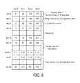
- FIG. 6 is a data structure view illustrating the data structure of the control word.
- FIG. 6 illustrates the arrangement of the first words of 256 basic frames (i.e. control words) included in one hyperframe.
- the area specified by "#X" in FIG. 6 indicates the control word of the basic frame with a basic frame number of X.
- the control words of the basic frames with X 64, 128 and 192 (i.e. Z.64.Y, Z.128.Y, and Z.192.Y)
- the synchronization timing data is stored.
- the slow control and management data is stored.
- the L1 inband protocol is stored.
- Each of the control words of the basic frames with X 3 to 15, 67 to 79, 131 to 143 and 195 to 207 (i.e.
- the L1 inband protocol is reserved as a reserved area.
- P 16 to P-1 (wherein P is a variable specified by a pointer for the fast control and management data)
- 80 to P+63, 144 to P+127 and 208 to P+191 i.e. Z.16.Y to Z.P-1.Y, Z.80.Y to Z.P+63.Y, Z.144.Y to Z.P+127.Y, and Z.208.Y to Z.P+191.Y
- the vender specific information is stored.
- the operation of the wireless base station 1 i.e. the operations of the REC 100 and the RE 200 will be explained.
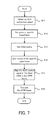
- FIG. 7 is a flowchart illustrating a flow of operation of the REC 100 included in the wireless base station 1 in the first embodiment.
- the CPU 103 included in the REC 100 obtains an ALD connection speed for transmitting the ALD control signal to the RE 200 (step S11).
- the CPU 103 may obtain the ALD connection speed by querying the ALD 300.
- the CPU 103 may also obtain the ALD connection speed set in advance.
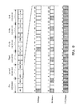
- the CPU 103 included in the REC 100 designates a specific hyperframe into which the ALD control signal is embedded, in order to satisfy the ALD connection speed obtained in the step S11 (step S12). More specifically, the CPU 103 generates divisional frame groups (in other words, conversion frames) into which 150 hyperframes are divided by the predetermined number of frames. Then, the CPU 103 designates the hyperframe which regularly or periodically appears in each conversation frame, as a specific hyperframe.
- divisional frame groups in other words, conversion frames
- the CPU 103 included in the REC 100 may designate the basic frame into which the ALD control signal is embedded, in the specific hyperframe. More specifically, in the first embodiment, the ALD control signal is embedded in the "slow control and management data area" in the CPRI frame.
- FIG. 8 is a data structure view illustrating the aspect of designating the specific hyperframe into which the ALD control signal is embedded.
- the CPU 103 may designate all the hyperframes in each conversion frame as the specific hyperframes.
- the example illustrated in FIG. 8 is one example.
- the CPU 103 included in the REC 100 sets initial timing at which the ALD control signal is embedded in the CPRI frame (step S13). In other words, the CPU 103 sets timing to start to embed the ALD control signal in the CPRI frame.
- the CPU 103 included in the REC 100 notifies the RE 200 of specific information for specifying the specific hyperframe, via the CPRI framer 102 and the CPRI link 500 (step S 14).
- the specific information may include the hyperframe number of the specific hyperframe. This allows the RE 200 to relatively easily specify the specific hyperframe.
- the specific information may include at least one of the initial timing, cycles at which the specific hyperframe appears, and the size of the conversion frame. This allows the RE 200 to specify the specific hyperframe while reducing the size of the specific information. In any cases, as long as the information can properly specify the specific hyperframe, it can be used as the specific information.
- the specific information may further include information for specifying the basic frame(s) in which the ALD control signal is embedded (in other words, the control word(s) in which the ALD control signal is embedded) in the specific hyperframe.
- the specific information may include the basic frame number(s) of the basic frame(s) in which the ALD control signal is embedded.
- the control word is specified by a control word number Xs (refer to FIG. 6 ) and a row number Ns and that the row number(s) Ns of the control word(s) in which the ALD control signal is embedded (i.e. the control word(s) which is the slow control and management data area) is all 1
- the specific information may also include the control word number Xs. In any cases, as long as the information can properly specify the basic frame(s) in which the ALD control signal is embedded in the specific hyperframe, it can be used as the specific information.
- the CPRI framer 102 included in the REC 100 generates the CPRI frame while embedding the ALD control signal transmitted from the ALD controller 400, under the control of the CPU 103 (step S15).
- each of the ALD control signal and the slow control and management data area complies with an HDLC protocol, and thus the CPRI framer 102 embeds the ALD control signal in the CPRI frame by performing simple mapping by a bit unit.
- the CPRI framer 102 included in the REC 100 transmits the CPRI frame to the RE 200 via the CPRI link 500 (step S16).
- the ALD control signal may be transmitted not only from the ALD controller 400 to the ALD 300 but also from the ALD 300 to the ALD controller 400. Therefore, the REC 100 preferably extracts the ALD control signal embedded in the CPRI frame, in addition to or instead of embedding the ALD control signal in the CPRI frame.
- the operation of extracting the ALD control signal on the REC 100 is performed by the CPRI framer 102 which operates under the control of the CPU 103, in the same aspect as that of an operation of extracting the ALD control signal on the RE 200 described later.
- FIG. 9 is a flowchart illustrating a flow of operation of the RE 200 included in the wireless base station 1 in the first embodiment.
- the CPU 203 included in the RE 200 obtains the specific information transmitted from the REC 100 via the CPRI framer 202 and the CPRI link 500 (step S21).
- the CPRI framer 202 included in the RE 200 judges whether or not the specific hyperframe is received, on the basis of the specific information obtained in the step S21, under the control of the CPU 203 (step S22).
- the judgment operation in the step S22 is continued.
- the CPRI framer 202 included in the RE 200 extracts the ALD control signal from the slow control and management data area_in the specific hyperframe (step S23).
- the CPRI framer 202 included in the RE 200 transmits the ALD control signal extracted in the step S23 to the ALD 300 (step S24).
- the ALD 300 operates under the control by the ALD control signal.
- the ALD control signal may be transmitted not only from the ALD controller 400 to the ALD 300, but also from the ALD 300 to the ALD controller 400 in some cases. Therefore, the RE 200 preferably embeds the ALD control signal in the CPRI frame, in addition to or instead of extracting the ALD control signal embedded in the CPRI frame.
- the operation of embedding the ALD control signal in the CPRI frame on the RE 200 is performed by the CPRI framer 202, which operates under the control of the CPU 203, in the same aspect as that of the operation of embedding the ALD control signal in the CPRI frame on the REC 100 described above.
- the specific hyperframe or the like may not be designated on the RE 200 side.
- the ALD control signal may be embedded into the specific hyperframe designated by the specific information, notice of which is given from the REC 100.
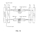
- FIG. 10 is a schematic diagram briefly illustrating the operation of the wireless base station 1 in the first embodiment.
- the REC 100 embeds the ALD control signal (in other words, the ALD control signal transmitted from the ALD controller 400) in the slow control and management data area of the specific hyperframe in the CPRI frame.
- the RE 200 extracts the ALD control signal embedded in the slow control and management data area of the specific hyperframe in the CPRI frame.
- the RE 200 transmits the extracted ALD control signal to the ALD 300.
- the RE 200 embeds the ALD control signal (in other words, the ALD control signal which is to be transmitted to the ALD controller 400) in the slow control and management data area of the specific hyperframe in the CPRI frame.
- the REC 100 extracts the ALD control signal embedded in the slow control and management data area of the specific hyperframe in the CPRI frame.
- the REC 100 transmits the extracted ALD control signal to the ALD controller 400.
- the ALD control signal for controlling the ALD 300 can be embedded in the CPRI frame.
- the ALD control signal which complies with a HDLC protocol (High Level Data Link Control) protocol can be embedded in the slow control and management data area which complies with the HDLC protocol.
- the ALD control signal can be embedded in the CPRI frame without changing the structure of the CPRI frame.
- the ALD control signal can be transmitted by using the CPRI link 500 between the REC 100 and the RE 200.
- a dedicated line for transmitting the ALD control signal e.g. a dedicated line between the ALD controller 400 and the ALD 300 may not be provided.
- the ALD control signal can be embedded into the specific hyperframe which appears regularly or periodically.
- the ALD control signal may not be randomly embedded into the CPRI frame.
- the ALD control signal can be embedded in the control word of the basic frame which appears regularly or periodically (i.e. the slow control and management data area).
- the RE 200 can extract the ALD control signal, relatively easily, by referring to the specific hyperframe and the basic frame with focusing on the regularity or periodicity. In other words, it is possible to relatively easily perform synchronization for the transmission and the reception of the ALD control signal between the REC 100 and the RE 200.
- the ALD control signal can be properly embedded in the CPRI frame.
- a special physical apparatus e.g. a capsulating apparatus or the like for embedding the ALD control signal in the CPRI frame may not be provided, and it is possible to ensure the general versatility of the wireless base station 1.
- the wireless base station 1 in the first embodiment notice of the specific information for specifying the specific hyperframe in which the ALD control signal is embedded (moreover, the basic frame in which the ALD control signal is embedded) is given from the REC 100 to the RE 200. Therefore, the RE 200 can extract the ALD control signal from the specific hyperframe, relatively easily, with respect to notice information. In other words, it is possible to relatively easily perform the synchronization necessary for the transmission / reception of the ALD control signal between the REC 100 and the RE 200.
- a wireless base station 2 in a second embodiment will be explained.
- the same constituents and operations as those of the wireless base station I in the first embodiment will carry the same reference numerals and step numbers, and the detailed explanation thereof will be omitted.
- FIG. 11 is a block diagram illustrating one example of the basic structure of the wireless base station 2 in the second embodiment.
- the wireless base station 2 in the second embodiment includes a REC 100, a RE 200a, a RE 200b, an ALD 300a connected to the RE 200a, an ALD 300b connected to the RE 200b, an ALD controller 400a for controlling the ALD 300a, and an ALD controller 400b for connecting the ALD 300b.
- the wireless base station 2 in the second embodiment has such a structure that two (i.e. a plurality of) REs 200 are connected to one REC 100 via a common public radio interface (CPRI) link 500 and that the ALD 300 is connected to each RE 200.
- CPRI public radio interface
- each of the structures of the REC 100 and the RE 200 is the same as explained in the first embodiment; however, the operation of each of the REC 100 and the RE 200 may be different from the operation explained in the first embodiment. Hereinafter, an explanation will be focused on the different operation.
- the operation of the wireless base station 2 i.e. the operations of the REC 100 and the RE 200 will be explained.
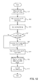
- FIG. 12 is a flowchart illustrating a flow of operations of the REC 100 included in the wireless base station 2 in the second embodiment.
- the REC 100 obtains the ALD connection speed (the step S11), designates the specific hyperframe (the step S12), and sets the initial timing (the step S13).
- the CPU 103 included in the REC 100 judges whether or not the plurality of REs 200 are connected (step S31).
- the REC 100 notifies of the specific information for specifying the specific hyperframe (the step S14), generates the CPRI frame while embedding the ALD control signal (the step S15), and transmits the CPRI frame to the RE 200 (the step S16).
- the CPU 103 included in the REC 100 notifies the RE 200 of the specific information for specifying the specific hyperframe, via the CPRI framer 102 and the CPRI link 500 (the step S14).
- the specific information in the second embodiment preferably includes information for specifying the control word number Xs assigned in the step S32.
- the CPRI framer 102 included in the REC 100 generates the CPRI frame while embedding the ALD control signal transmitted from the ALD controller 400, under the control of the CPU 103 (the step S15).
- the CPRI framer 102 embeds the ALD control signal, which is transmitted from the ALD controller 400a and which is transmitted to the ALD 300a, in the control word (or slow control and management data area) corresponding to the control word number Xs (e.g. 0) assigned to the RE 200a in the step S32.
- the CPRI framer 102 embeds the ALD control signal, which is transmitted from the ALD controller 400b and which is transmitted to the ALD 300b, in the control word (or slow control and management data area) corresponding to the control word number Xs (e.g. 1) assigned to the RE 200b in the step S32.
- the CPRI framer 102 included in the REC 100 transmits the CPRI frame to the RE 200 via the CPRI link 500 (the step S16).
- FIG. 13 is a flowchart illustrating a flow of operations of the RE 200 included in the wireless base station 2 in the second embodiment.
- the CPU 203 included in the RE 200 obtains the specific information (the step S21) and judges whether or not the specific hyperframe is received (the step S22).
- the judgment operation in the step S22 is continued.
- the CPRI framer 202 included in the RE 200 extracts the ALD control signal from the slow control and management data area in the specific hyperframe (step S41).
- the CPRI framer 202 included in the RE 200 transmits the ALD control signal extracted in the step S41, to the ALD 300 (the step S24). More specifically, the RE 200a transmits the ALD control signal extracted in the step S41, to the ALD 300a. On the other hand, the RE 200b transmits the ALD control signal extracted in the step S41, to the ALD 300b. As a result, the ALDs 300a and 300b operate under the control by the ALD control signal.
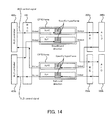
- FIG. 14 is a schematic diagram briefly illustrating the operation of the wireless base station 2 in the second embodiment.
- the REC 100 embeds the ALD control signal for controlling the ALD 300a (in other words, the ALD control signal transmitted from the ALD controller 400a) in the slow control and management data area with a control word number of "0" in the specific hyperframe. Moreover, the REC 100 embeds the ALD control signal for controlling the ALD 300b (in other words, the ALD control signal transmitted from the ALD controller 400b) in the slow control and management data area with a control word number of "1" in the specific hyperframe.
- the RE 200a extracts the ALD control signal from the slow control and management data area with a control word number of "0" in the specific hyperframe and transmits the extracted ALD control signal to the ALD 300a.
- the RE 200b extracts the ALD control signal from the slow control and management data area with a control word number of "1" in the specific hyperframe and transmits the extracted ALD control signal to the ALD 300b.
- the RE 200a embeds the ALD control signal for controlling the ALD 300a (in other words, the ALD control signal transmitted to the ALD controller 400a) in the slow control and management data area with a control word number of "0" in the specific hyperframe.
- the RE 200b embeds the ALD control signal for controlling the ALD 300b (in other words, the ALD control signal transmitted to the ALD controller 400b) in the slow control and management data area with a control word number of "1" in the specific hyperframe.
- the REC 100 extracts the ALD control signal from the slow control and management data area with a control word number of "0" in the specific hyperframe and transmits the extracted ALD control signal to the ALD controller 400a. Moreover, the REC 100 extracts the ALD control signal from the slow control and management data area with a control word number of "1" in the specific hyperframe and transmits the extracted ALD control signal to the ALD controller 400b.
- the wireless base station 2 in the second embodiment it is possible to receive the same effects as those received by the wireless base station 1 in the first embodiment.
- the control word number Xs is used as a substantive address (i.e. an address in the communication between the ALD 300 and the ALD controller 400). Therefore, even if the plurality of REs 200a and 200b are connected to the REC 100 which is connected to the plurality of ALD controllers 400a and 400b, it is possible to appropriately transmit the ALD control signals from the plurality of ALD controllers 400a and 400b to the corresponding ALDs 300a and 300b via the corresponding REs 200a and 200b. In the same manner, it is possible to appropriately transmit the ALD control signals from the plurality of ALDs 300a and 300b to the corresponding ALD controllers 400a and 400b via the corresponding REs 200a and 200b.
- the aforementioned explanation states the example in which two REs 200a and 200b are connected to one REC 100. However, even if three or more REs are connected to one REC 100 and the ALD 300 is connected to each RE 200, obviously, it is possible to receive the same effects by performing the same operation.
- FIG. 15 is a block diagram illustrating one example of the basic structure of the wireless base station 3 in the third embodiment.
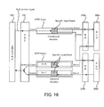
- FIG. 16 is a schematic diagram illustrating the operation of the wireless base station 3 in the third embodiment.
- the wireless base station 3 in the third embodiment includes a REC 100, a RE 200a, a RE 200b, an ALD 300a connected to the RE 200a, an ALD 300b connected to the RE 200b, and an ALD controller 400 for controlling the ALD 300a and the ALD 300b.
- a single ALD network is formed while the plurality of REs 200 and the plurality of ALDs 300 are provided.
- each of the REC 100 and the RE 200 is the same as the structure explained in the first embodiment; however, the operation of each of the REC 100 and the RE 200 may be different from the operation explained in the first embodiment. Hereinafter, an explanation will be focused on the different operation.
- the operations in the same aspects as in the first embodiment are performed.
- the REC 100 embeds the ALD control signal for controlling the ALDs 300a and 300b (in other words, the ALD control signal transmitted from the ALD controller 400) in the slow control and management data area of the specific hyperframe in the CPRI frame.
- the RE 200a extracts the ALD control signal embedded in the slow control and management data area of the specific hyperframe in the CPRI frame and transmits the extracted ALD control signal to the ALD 300a.
- the RE 200b extracts the ALD control signal embedded in the slow control and management data area of the specific hyperframe in the CPRI frame and transmits the extracted ALD control signal to the ALD 300b.
- the same ALD control signal is transmitted from the REC 100 to each of the RE 200a and the RE 200b.
- Each of the ALD 300a and the ALD 300b performs the operation based on the ALD control signal, by extracting messages to each of the ALD 300a and the ALD 300b from the ALD control signal.
- the RE 200a embeds the ALD control signal for controlling the ALD 300a (in other words, the ALD control signal transmitted from the ALD 300a to the ALD controller 400) in the slow control and management data area with a control word number of "0" in the specific hyperframe.
- the RE 200b embeds the ALD control signal for controlling the ALD 300b (in other words, the ALD control signal transmitted from the ALD 300b to the ALD controller 400) in the slow control and management data area with a control word number of "1" in the specific hyperframe.
- the REC 100 extracts the ALD control signal from the slow control and management data area with a control word number of "0" in the specific hyperframe and extracts the ALD control signal from the slow control and management data area with a control word number of "1" in the specific hyperframe.
- the REC 100 also transmits a synthesized signal obtained by bit-adding the extracted two types of ALD control signals, to the ALD controller 400.
- the wireless base station 3 in the third embodiment it is possible to receive the same effects as those received by the wireless base station 1 in the first embodiment and the wireless base station 2 in the second embodiment.
- the wireless base station 3 in the third embodiment even if the plurality of REs 200a and 200b and the plurality of ALDs 300a and 300b are disposed in one ALD network, it is possible to appropriately transmit the ALD control signals from the ALD controller 400 to each of the ALDs 300a and 300b, via the corresponding REs 200a and 200b. In the same manner, it is possible to appropriately transmit the ALD control signals from the ALDs 300a and 300b to the corresponding ALD controller 400, via the corresponding REs 200a and 200b. In other words, it is possible to relatively easily perform synchronization for the transmission and the reception of the ALD control signal between the REC 100 and the REs 200a and 200b.
- the aforementioned explanation states the example in which two REs 200a and 200b are connected to one REC 100. However, even if three or more REs are connected to one REC 100 and the ALD 300 is connected to each RE 200, obviously, it is possible to receive the same effects by performing the same operations.
- a wireless base station including:
- wireless controlling apparatus further includes:
- the wireless base station wherein the wireless controlling apparatus is connected to each of at least a first wireless apparatus and a second wireless apparatus, and the embedding processor embeds a first control signal, which is to control the wireless device connected to the first wireless apparatus, in a first area portion of the control and management information area in the specific frame and embeds a second control signal, which is to control the wireless device connected to the second wireless apparatus, in a second area portion different from the first area portion of the control and management information area in the specific frame.
- the wireless base station according to any one of the additional statements 1 to 3, wherein the transmission link adopts a common public radio interface (CPRI) which is specification of an internal interface of the wireless base station, and the transmission frame is defined by the CPR1.
- CPRI common public radio interface
- control and management information area is a Slow C&M.
- wireless apparatus further includes:
- wireless controlling apparatus further includes:
- a wireless controlling apparatus connected to a wireless apparatus via a transmission link including: an embedding processor for embedding a control signal, which is to control a wireless device connected to the wireless apparatus, in a control and management information area in a specific frame, the specific frame being regularly assigned to each frame group including a predetermined number of frames of a plurality of frames included in a transmission frame transmitted via the transmission link; and a transmitter for transmitting the transmission frame to the wireless apparatus via the transmission link.
- a wireless apparatus connected to a wireless controlling apparatus via a transmission link the wireless controlling apparatus embedding a control signal, which is to control a wireless device connected to the wireless apparatus, in a control and management information area in a specific frame, the specific frame being regularly assigned to each frame group including a predetermined number of frames of a plurality of frames included in a transmission frame transmitted via the transmission link, the wireless controlling apparatus transmitting the transmission frame via the transmission link, the wireless apparatus including:
- a communication method in a wireless base station in which a wireless apparatus and a wireless controlling apparatus for controlling the wireless apparatus are connected via a transmission link including:
Landscapes
- Engineering & Computer Science (AREA)
- Computer Networks & Wireless Communication (AREA)
- Signal Processing (AREA)
- Mobile Radio Communication Systems (AREA)
Applications Claiming Priority (1)
| Application Number | Priority Date | Filing Date | Title |
|---|---|---|---|
| JP2009285411A JP5338648B2 (ja) | 2009-12-16 | 2009-12-16 | 無線基地局、無線制御装置及び無線装置、並びに通信方法 |
Publications (2)
| Publication Number | Publication Date |
|---|---|
| EP2337423A2 true EP2337423A2 (fr) | 2011-06-22 |
| EP2337423A3 EP2337423A3 (fr) | 2014-11-19 |
Family
ID=43769067
Family Applications (1)
| Application Number | Title | Priority Date | Filing Date |
|---|---|---|---|
| EP10192435.5A Withdrawn EP2337423A3 (fr) | 2009-12-16 | 2010-11-24 | Station de base sans fil, appareil sans fil, appareil de contrôle sans fil et procédé de communication |
Country Status (3)
| Country | Link |
|---|---|
| US (1) | US8676263B2 (fr) |
| EP (1) | EP2337423A3 (fr) |
| JP (1) | JP5338648B2 (fr) |
Cited By (1)
| Publication number | Priority date | Publication date | Assignee | Title |
|---|---|---|---|---|
| US10425202B2 (en) | 2015-09-23 | 2019-09-24 | Telefonaktiebolaget Lm Ericsson (Publ) | Robust wireless radio transmission |
Families Citing this family (10)
| Publication number | Priority date | Publication date | Assignee | Title |
|---|---|---|---|---|
| WO2011144085A2 (fr) | 2011-05-25 | 2011-11-24 | 华为技术有限公司 | Procédé d'émission de données et noeud b |
| CN103580780B (zh) * | 2012-07-23 | 2018-03-09 | 中兴通讯股份有限公司 | 数据传输方法及装置 |
| CN102833770B (zh) * | 2012-08-14 | 2016-08-24 | 华为技术有限公司 | 电调天线设备及其关联小区的方法、天线组件及基站 |
| WO2014029430A1 (fr) | 2012-08-22 | 2014-02-27 | Telefonaktiebolaget L M Ericsson (Publ) | Distribution de données de retard de trajet dans un réseau de communications orienté connexion |
| WO2014037061A1 (fr) * | 2012-09-06 | 2014-03-13 | Telefonaktiebolaget L M Ericsson (Publ) | Utilisation de l'interface radio publique commune sur des réseaux asymétriques |
| CN104320801B (zh) * | 2014-10-22 | 2018-09-21 | 电子科技大学中山学院 | 不可靠通信环境下的ald设备扫描方法 |
| KR101771241B1 (ko) * | 2014-11-25 | 2017-08-25 | 주식회사 케이엠더블유 | 다중 대역 기지국 시스템에 사용되는 컴바이너 및 컴바이너 제어 방법 |
| WO2019046047A1 (fr) * | 2017-09-01 | 2019-03-07 | Commscope Technologies Llc | Systèmes et procédés de communication sans fil dans une structure d'antenne de station de base |
| CN110769520A (zh) * | 2018-07-25 | 2020-02-07 | 上海华为技术有限公司 | 天线设备与基站的连接方法、天线设备和基站 |
| CN112087290B (zh) * | 2019-06-12 | 2023-05-02 | 深圳市中兴微电子技术有限公司 | 一种控制字的传输方法和装置、计算机可读存储介质 |
Citations (3)
| Publication number | Priority date | Publication date | Assignee | Title |
|---|---|---|---|---|
| JP2007511955A (ja) | 2003-11-17 | 2007-05-10 | テレフオンアクチーボラゲット エル エム エリクソン(パブル) | 分散型無線基地局の内部インターフェース上の非依存送信のカプセル化 |
| JP2007124608A (ja) | 2005-10-26 | 2007-05-17 | Utstarcom Telecom Co Ltd | 分散された基地局システムにおけるcpriベースのマルチプロトコル信号伝送方法および装置 |
| JP2008131651A (ja) | 2006-11-21 | 2008-06-05 | Samsung Electronics Co Ltd | 多重アンテナを使用する基地局システムにおける二重化支援装置及びその方法 |
Family Cites Families (5)
| Publication number | Priority date | Publication date | Assignee | Title |
|---|---|---|---|---|
| US7460513B2 (en) | 2003-11-17 | 2008-12-02 | Telefonaktiebolaget Lm Ericsson (Publ) | Encapsulation of diverse protocols over internal interface of distributed radio base station |
| US7856029B2 (en) | 2003-11-17 | 2010-12-21 | Telefonaktiebolaget Lm Ericsson (Publ) | Pre-start-up procedure for internal interface of distributed radio base station |
| US8908650B2 (en) * | 2004-10-12 | 2014-12-09 | Telefonaktiebolaget Lm Ericsson (Publ) | Interface, apparatus, and method for communication between a radio equipment control node and one or more remote radio equipment nodes |
| US20060277309A1 (en) * | 2005-06-03 | 2006-12-07 | Ems Technologies, Inc. | Method and system for discovering antenna line devices |
| EP2437413A4 (fr) | 2009-05-27 | 2014-12-24 | Fujitsu Ltd | Dispositif de commande de dispositifs de radiocommunication, dispositif de radiocommunication et procédé de communication |
-
2009
- 2009-12-16 JP JP2009285411A patent/JP5338648B2/ja not_active Expired - Fee Related
-
2010
- 2010-11-24 EP EP10192435.5A patent/EP2337423A3/fr not_active Withdrawn
- 2010-12-09 US US12/963,775 patent/US8676263B2/en not_active Expired - Fee Related
Patent Citations (3)
| Publication number | Priority date | Publication date | Assignee | Title |
|---|---|---|---|---|
| JP2007511955A (ja) | 2003-11-17 | 2007-05-10 | テレフオンアクチーボラゲット エル エム エリクソン(パブル) | 分散型無線基地局の内部インターフェース上の非依存送信のカプセル化 |
| JP2007124608A (ja) | 2005-10-26 | 2007-05-17 | Utstarcom Telecom Co Ltd | 分散された基地局システムにおけるcpriベースのマルチプロトコル信号伝送方法および装置 |
| JP2008131651A (ja) | 2006-11-21 | 2008-06-05 | Samsung Electronics Co Ltd | 多重アンテナを使用する基地局システムにおける二重化支援装置及びその方法 |
Non-Patent Citations (1)
| Title |
|---|
| ANONYMOUS: "AIF Module - Antenna Interface Module in the Embedded Processor TMS320C6474 - Texas Instruments Wiki", 28 September 2009 (2009-09-28), pages 1 - 8, XP055271952, Retrieved from the Internet <URL:http://processors.wiki.ti.com/index.php/AIF_Module> [retrieved on 20160511] * |
Cited By (1)
| Publication number | Priority date | Publication date | Assignee | Title |
|---|---|---|---|---|
| US10425202B2 (en) | 2015-09-23 | 2019-09-24 | Telefonaktiebolaget Lm Ericsson (Publ) | Robust wireless radio transmission |
Also Published As
| Publication number | Publication date |
|---|---|
| JP5338648B2 (ja) | 2013-11-13 |
| JP2011130095A (ja) | 2011-06-30 |
| US20110143813A1 (en) | 2011-06-16 |
| EP2337423A3 (fr) | 2014-11-19 |
| US8676263B2 (en) | 2014-03-18 |
Similar Documents
| Publication | Publication Date | Title |
|---|---|---|
| US8676263B2 (en) | Wireless base station, wireless apparatus, wireless controlling apparatus, and communication method | |
| US7085560B2 (en) | Wireless communications device with artificial intelligence-based distributive call routing | |
| JP4505446B2 (ja) | Cdmaトラフィックをumts対応cpriインタフェイスを介して送信する方法 | |
| CN101657028B (zh) | 一种建立s1接口连接的方法、设备及系统 | |
| US6925072B1 (en) | System and method for transmitting control information between a control unit and at least one sub-unit | |
| EP0670640A2 (fr) | Dispositif pour un système de radiocommunication TDMA/TDD avec une structure pour combiner des intervalles temporels | |
| AU2002301712B2 (en) | Signal supply apparatus and method for public and private mobile communication system | |
| CN102647813B (zh) | 无线通信方法以及分布式基站系统 | |
| JP5187443B2 (ja) | 無線装置制御装置、無線装置、および通信方法 | |
| US8301131B2 (en) | Method for optimizing the transmission resources by local loopback in a mobile radio communication cellular network, network and local adapters thereof | |
| CN111586704B (zh) | 基于同轴电缆进行5g室内深度覆盖的系统 | |
| CN104579479A (zh) | 一种分布式基站系统及其传输e1信号和以太网信号的方法 | |
| JP3007690B2 (ja) | 情報を一般の送信回線網で送信するための方法 | |
| US6636492B1 (en) | Apparatus for interfacing between mobile switching center and interworking function unit | |
| KR20050006383A (ko) | 무선가입자망의 가입자접속장치에서 패킷 형태의 과금갱신 정보 전송 방법 | |
| CN102497233A (zh) | 利用数字光纤直放站传输以太网信号的方法 | |
| JP2010166509A (ja) | フレーム変換方法及びエントランス無線装置 | |
| CN205305126U (zh) | 一种无线传输通信设备及无线传输通信系统 | |
| AU745622B2 (en) | Mobile communication system including base stations each having definite number of traffic channels | |
| KR101106697B1 (ko) | 이더넷에서 흐름 제어 장치 및 방법 | |
| KR100345683B1 (ko) | 무선 가입자망 시스템에서 기지국과 기지국 제어기간 무선 광 정합장치 및 그 방법 | |
| KR100699985B1 (ko) | 비차폐 꼬임 쌍 케이블을 통한 디지털 중간주파수 신호의기가비트 전송 시스템 | |
| KR100267275B1 (ko) | 유선 통신망을 이용한 무선통신 시스템 | |
| EP1795020A2 (fr) | Dispositif de communication sans fil avec acheminement d'appel fonde sur l'intelligence artificielle | |
| WO1998028934A1 (fr) | Systeme radio pour reseau fixe |
Legal Events
| Date | Code | Title | Description |
|---|---|---|---|
| PUAI | Public reference made under article 153(3) epc to a published international application that has entered the european phase |
Free format text: ORIGINAL CODE: 0009012 |
|
| AK | Designated contracting states |
Kind code of ref document: A2 Designated state(s): AL AT BE BG CH CY CZ DE DK EE ES FI FR GB GR HR HU IE IS IT LI LT LU LV MC MK MT NL NO PL PT RO RS SE SI SK SM TR |
|
| AX | Request for extension of the european patent |
Extension state: BA ME |
|
| PUAL | Search report despatched |
Free format text: ORIGINAL CODE: 0009013 |
|
| AK | Designated contracting states |
Kind code of ref document: A3 Designated state(s): AL AT BE BG CH CY CZ DE DK EE ES FI FR GB GR HR HU IE IS IT LI LT LU LV MC MK MT NL NO PL PT RO RS SE SI SK SM TR |
|
| AX | Request for extension of the european patent |
Extension state: BA ME |
|
| RIC1 | Information provided on ipc code assigned before grant |
Ipc: H04W 88/08 20090101AFI20141010BHEP |
|
| 17P | Request for examination filed |
Effective date: 20150114 |
|
| RBV | Designated contracting states (corrected) |
Designated state(s): AL AT BE BG CH CY CZ DE DK EE ES FI FR GB GR HR HU IE IS IT LI LT LU LV MC MK MT NL NO PL PT RO RS SE SI SK SM TR |
|
| 17Q | First examination report despatched |
Effective date: 20160518 |
|
| STAA | Information on the status of an ep patent application or granted ep patent |
Free format text: STATUS: THE APPLICATION IS DEEMED TO BE WITHDRAWN |
|
| 18D | Application deemed to be withdrawn |
Effective date: 20160929 |