EP2337609B1 - Leistungsbeurteilung und adaptierung einer akustischen kommunikationsverbindung - Google Patents
Leistungsbeurteilung und adaptierung einer akustischen kommunikationsverbindung Download PDFInfo
- Publication number
- EP2337609B1 EP2337609B1 EP09790053.4A EP09790053A EP2337609B1 EP 2337609 B1 EP2337609 B1 EP 2337609B1 EP 09790053 A EP09790053 A EP 09790053A EP 2337609 B1 EP2337609 B1 EP 2337609B1
- Authority
- EP
- European Patent Office
- Prior art keywords
- acoustic
- link
- performance
- parameter
- implantable medical
- Prior art date
- Legal status (The legal status is an assumption and is not a legal conclusion. Google has not performed a legal analysis and makes no representation as to the accuracy of the status listed.)
- Not-in-force
Links
Images



Classifications
-
- A—HUMAN NECESSITIES
- A61—MEDICAL OR VETERINARY SCIENCE; HYGIENE
- A61N—ELECTROTHERAPY; MAGNETOTHERAPY; RADIATION THERAPY; ULTRASOUND THERAPY
- A61N1/00—Electrotherapy; Circuits therefor
- A61N1/18—Applying electric currents by contact electrodes
- A61N1/32—Applying electric currents by contact electrodes alternating or intermittent currents
- A61N1/36—Applying electric currents by contact electrodes alternating or intermittent currents for stimulation
- A61N1/372—Arrangements in connection with the implantation of stimulators
- A61N1/37211—Means for communicating with stimulators
-
- A—HUMAN NECESSITIES
- A61—MEDICAL OR VETERINARY SCIENCE; HYGIENE
- A61N—ELECTROTHERAPY; MAGNETOTHERAPY; RADIATION THERAPY; ULTRASOUND THERAPY
- A61N1/00—Electrotherapy; Circuits therefor
- A61N1/18—Applying electric currents by contact electrodes
- A61N1/32—Applying electric currents by contact electrodes alternating or intermittent currents
- A61N1/36—Applying electric currents by contact electrodes alternating or intermittent currents for stimulation
- A61N1/372—Arrangements in connection with the implantation of stimulators
- A61N1/37211—Means for communicating with stimulators
- A61N1/37217—Means for communicating with stimulators characterised by the communication link, e.g. acoustic or tactile
-
- A—HUMAN NECESSITIES
- A61—MEDICAL OR VETERINARY SCIENCE; HYGIENE
- A61N—ELECTROTHERAPY; MAGNETOTHERAPY; RADIATION THERAPY; ULTRASOUND THERAPY
- A61N1/00—Electrotherapy; Circuits therefor
- A61N1/18—Applying electric currents by contact electrodes
- A61N1/32—Applying electric currents by contact electrodes alternating or intermittent currents
- A61N1/36—Applying electric currents by contact electrodes alternating or intermittent currents for stimulation
- A61N1/362—Heart stimulators
- A61N1/37—Monitoring; Protecting
- A61N1/3706—Pacemaker parameters
Definitions
- Implantable medical devices such as pacemakers and implantable cardioverter defibrillators are utilized in monitoring and regulating various conditions within the body.
- An implantable cardioverter defibrillator may be utilized in cardiac rhythm management applications to monitor the rate and rhythm of the heart and for delivering various therapies such as cardiac pacing, cardiac defibrillation, and/or cardiac therapy.
- the IMD can be configured to sense various physiological parameters occurring within the body to determine the occurrence of any abnormalities in the operation of the patient's heart. Based on these sensed parameters, the IMD may then deliver an appropriate treatment to the patient.
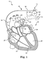
- FIG. 1 is a schematic view of an illustrative system 10 employing a remote implantable medical device (IMD) located within the body of a patient.
- the system 10 illustratively a cardiac rhythm management system for providing cardiac rhythm management to a patient, includes an external monitor 12 (e.g., an external wand or programmer), a pulse generator 14 implanted within the body at a location below the patient's skin, and at least one remote IMD 16 implanted deeply within the patient's body such as in one of the arteries or ventricles of the patient's heart 18.
- the heart 18 includes a right atrium 20, a right ventricle 22, a left atrium 24, a left ventricle 26, and an aorta 28.
- the right ventricle 22 leads to the main pulmonary artery 30 and the branches 32,34 of the main pulmonary artery 30.
- the pulse generator 14 will be implanted at a location adjacent to the location of the external monitor 12, which may lie adjacent to the exterior surface of the patient's skin.
- the distal portion of a second lead may be implanted in the right atrium 20.
- another lead may be implanted in the left side of the heart 18 (e.g., in the coronary veins) to stimulate the left side of the heart 18.
- Other types of leads such as epicardial leads may also be utilized in addition to, or in lieu of, the lead 36 depicted in Figure 1 .
- the remote IMD 16 can be configured to perform one or more designated functions, including the sensing of one or more physiological parameters within the body.
- Example physiological parameters that can be measured using the remote IMD 16 can include, but are not limited to, blood pressure, blood flow, temperature, and strain.
- Various electrical, chemical, magnetic, and/or sound properties may also be sensed within the body via the remote IMD 16.
- the remote IMD 16 is adapted to deliver a desired therapy (e.g., a pacing and/or defibrillation stimulus) to the patient's heart 18 or cardiovascular system.
- a desired therapy e.g., a pacing and/or defibrillation stimulus
- the remote IMD 16 comprises a pressure sensor implanted at a location deep within the body such as in the main pulmonary artery 30 or a branch 32,34 of the main pulmonary artery 30 (e.g., in the right or left pulmonary artery).
- a pressure sensor suitable for use in sensing pulmonary arterial pressure is described in United States Patent No. 6,764,446 , entitled “Implantable Pressure Sensors and Methods for Making and Using Them,” which is incorporated herein by reference in its entirety for all purposes.
- the remote IMD 16 can be used to aid in the prediction of heart decompensation of a heart failure patient and/or to aid in optimizing pacing and/or defibrillation therapy via the pulse generator 14 by taking pressure measurements within the body.
- the remote IMD 16 can be configured to sense, detect, measure, calculate, and/or derive other associated parameters such as flow rate, maximum and minimum pressure, peak-to-peak pressure, rms pressure, and/or pressure rate change.
- the pressure signal from the remote IMD 16 can be used to detect changes in arterial blood pressure during a cardiac cycle or across multiple cardiac cycles.
- the remote IMD 16 may be implanted in other regions of the patient's vasculature, in other body lumens, or in other areas of the body, and may comprise any type of chronically implanted device adapted to deliver therapy and/or monitor biological and chemical parameters, properties, and functions.
- the remote IMD 16 can be tasked, either alone or with other implanted or external devices, to provide various therapies within the body.
- the remote IMD 16 may comprise a glucose level sensor that can be used in conjunction with an insulin pump for providing insulin treatment to the patient.
- a single remote IMD 16 is depicted in Figure 1 , multiple such devices could be implanted at various locations within the body for sensing physiologic parameters and/or providing therapy at multiple regions within the body.
- An acoustic communication link may be established to permit wireless communications between the remote IMD 16 and the external device 12, between the remote IMD 16 and the pulse generator 14, and/or between the remote IMD 16 and another communicating device located inside or outside of the body.
- the external device 12 includes an acoustic transducer 42 adapted to transmit an acoustic signal 44 into the body for establishing an acoustic link between the remote IMD 16 and the external device 12.
- An acoustic transducer 46 coupled to the housing 48 of the remote IMD 16 is configured to receive the acoustic signal 44 transmitted by the external device 12.
- An example acoustic transducer suitable for use with the remote IMD 16 is described in United States Patent No. 6,140,740 , entitled “Piezoelectric Transducer,” which is expressly incorporated herein by reference in its entirety for all purposes.
- the transmission of the acoustic signal 44 to the remote IMD 16 can be used to activate the IMD 16 from a low-power, sleep state to an active, energized state.
- the acoustic signal 44 generated by the external device 12 can be used to wake up the remote IMD 16 from an initial, low-power state to an active state to take one or more sensor readings within the body and then transmit those readings to the external device 12, to the pulse generator 14, and/or to another device located inside or outside of the body.
- the acoustic signal 44 can be used to provide power to the remote IMD 16 and/or to recharge an energy storage device within the IMD 16 such as a rechargeable battery or power capacitor. In some embodiments, the acoustic signal 44 provides acoustical energy that can be converted into electrical energy to provide therapy to the patient, if desired.
- the system 10 of Figure 1 includes an external device 12 in acoustic communication with a remote IMD 16, in other embodiments the system 10 may employ other devices located inside or outside of the patient's body that acoustically communicate with the IMD 16.
- the pulse generator 14 can also include an acoustic transducer 50 adapted to transmit an acoustic signal 52 to the remote IMD 16 to establish an acoustic link between the pulse generator 14 and the remote IMD 16.
- the acoustic transducer 50 is coupled to an interior portion of the can 54 that encloses the various components of the pulse generator 14.
- the acoustic transducer 50 is located outside of the can 54, or is coupled to the pulse generator 14 through a feedthrough provided on the can 54.
- an acoustic link can be established between the remote IMD 16 and another device implanted within the body.
- an acoustic communication link can be established between a primary IMD 16 and one or more secondary IMDs 16 implanted within the body.
- FIG. 2 is a block diagram of an illustrative embodiment of the remote IMD 16 of Figure 1 .
- the remote IMD 16 includes an energy storage device 56, a physiological sensor 58, an acoustic switch 60 (including the acoustic transducer 46, a signal detector 62, and an activation/deactivation switch component 64), power control circuitry 66, and a controller 68.
- the energy storage device 56 may be non-rechargeable or rechargeable, and operates to supply power to the physiological sensor 58, the acoustic switch 60, the power control circuitry 66, and the controller 68.
- the power control circuitry 66 is operatively connected to the acoustic switch 60, and is used to regulate the supply of power from the energy storage device 56 to the physiological sensor 58 and the controller 68.
- the physiological sensor 58 performs functions related to the measurement of one or more physiological parameters within the body.
- the physiological sensor 58 comprises a pressure sensor adapted to measure blood pressure in a body vessel.
- the remote IMD 16 is implanted in a pulmonary artery of the patient, and the physiological sensor 58 is adapted to sense arterial blood pressure.
- An example remote IMD 16 suitable for sensing blood pressure within an artery is described, for example, in United States Provisional Patent Application No. 61/060,877 , entitled "Implantable Pressure Sensor with Automatic Measurement and Storage Capabilities".
- the physiological sensor 58 is adapted to generate a signal related to other sensed physiological parameters including, but not limited to, temperature, electrical impedance, position, strain, pH, blood flow, radiation level, and glucose level.
- the remote IMD 16 may also include a therapy delivery module 70 that performs one or more therapeutic functions (e.g., cardiac pacing, drug delivery) within the body in addition to, or in lieu of, the one or more sensing functions provided by the physiological sensor 58.
- the acoustic transducer 46 for the remote IMD 16 may include one or more piezoelectric transducer elements configured to transmit and receive acoustic signals. In a reception mode of operation, the acoustic transducer 46 is configured to receive the acoustic signal 44,52 transmitted from the external device and/or the pulse generator 14, which is fed to the controller 68 when the remote IMD 16 is in the active state. The acoustic transducer 46, or another acoustic transducer coupled to the remote IMD 16, is configured to transmit an outward acoustic signal 71 to the external device 12 and/or the pulse generator 14.
- the transmitted acoustic signal 71 can include sensor data obtained from the physiological sensor 58, information relating to the status or operation of the remote IMD 16 (e.g., power status, communication mode status, error correction information, etc.), as well as other information relating to the operation of the remote IMD 16.
- information relating to the status or operation of the remote IMD 16 e.g., power status, communication mode status, error correction information, etc.
- other information relating to the operation of the remote IMD 16 can include sensor data obtained from the physiological sensor 58, information relating to the status or operation of the remote IMD 16 (e.g., power status, communication mode status, error correction information, etc.), as well as other information relating to the operation of the remote IMD 16.
- the signal detector 62 is configured to generate an activation trigger signal to activate the remote IMD 16 via the activation/deactivation switch component 64.
- the activation trigger signal is generated by the signal detector 62 when the electrical signal generated by the acoustic transducer 46 exceeds a specific voltage threshold.
- the activation/deactivation switch component 64 is the component through which current is delivered from the energy storage device 56 to the controller 68 when actuated.
- the switch component 64 In response to the generation of the activation trigger signal by the signal detector 62, the switch component 64 is actuated to allow current to flow to the controller 68, thereby placing the remote IMD 16 in the active state.
- the switch component 64 can also be actuated to prevent current from flowing to the controller 68, thereby placing the remote IMD 16 in the standby state. Further details regarding the general construction and function of acoustic switches are disclosed in United States Patent No. 6,628,989 , entitled "Acoustic Switch And Apparatus And Methods For Using Acoustic Switches Within The Body".
- the external device 12 or the pulse generator 14 operates to generate a field (i.e., a wake-up field) that can be detected by a sensing module in the remote IMD 16 for the purpose of causing the remote IMD 16 to wake from the sleep state.
- the remote IMD 16 can include an antenna or inductive coil that receives an RF or inductive signal from the external device 12 or pulse generator 14 to wirelessly activate or deactivate the remote IMD 16 within the body.
- the controller 68 includes a processor 72 such as a microprocessor or microcontroller coupled to a memory device 74 that includes operating instructions and/or software for the remote IMD 16.
- the controller 70 also includes an oscillator or other timing circuitry 76 which directs the timing of activities performed by the remote IMD 16 once awoken from its low-power or sleep state.
- the timing circuitry 76 can be used for timing the physiologic measurements taken by the physiological sensor 58, and to generate timing markers to be associated with those measurements.
- the controller 68 including the processor 72, can be configured as a digital signal processor (DSP), a field programmable gate array (FPGA), an application specific integrated circuit (ASIC)-compatible device, and/or any other hardware components or software modules for processing, analyzing, storing data, and controlling the operation of the remote IMD 16.
- DSP digital signal processor
- FPGA field programmable gate array
- ASIC application specific integrated circuit
- the processor 72 can be configured to analyze, interpret, and/or process the received acoustic signals 44,52 as well as the signals received by the physiological sensor 58. As discussed further herein with respect to Figures 4-6 , the processor 72 is configured to run an adaptation algorithm or routine 78 that analyzes the performance of the acoustic link between the remote IMD 16 and the external device 12 and/or pulse generator 14, and responsive to such feedback, adjusts one or more operating parameters of the remote IMD 16 to ensure that the acoustic link is adequately maintained.
- a similar controller may be provided on the pulse generator 14 to permit the pulse generator 14 to measure an acoustic link established between the remote IMD 16 and the pulse generator, and responsive to such feedback, adjust one or more operating parameters of the pulse generator 14, if desired.
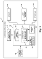
- FIG 3 is a block diagram of an illustrative embodiment of the external device 12 of Figure 1 .
- the external device 16 includes an acoustic transducer 42, an on-board sensor 80, a controller 82, a user feedback device 84, and an energy storage device 86.
- the external device 12 is a handheld device.
- the external device 12 is attached to a portion of the patient's body such as the patient's arm, neck, chest, thigh, or knee.
- the external device 12 can use any type of attachment mechanism, such as a strap, a patch, a belt, or any other means for coupling the device 12 to the patient's body.
- the sensor 80 may comprise a biosensor that generates a signal in response to a sensed physiological parameter.
- the sensor 80 comprises a barometric pressure sensor configured to measure barometric pressure for use in calibrating a pressure signal received from the remote IMD 16.
- the external device 12 may include one or more additional sensors such as an ECG electrode sensor, a systemic blood pressure sensor, a posture sensor, a global positioning system (GPS) sensor, an activity sensor, a temperature sensor, a timer, and/or an oximeter.
- GPS global positioning system
- the acoustic transducer 42 for the external device 12 is configured to both transmit and receive acoustic signals to and from the pulse generator 14 and remote IMD 16.
- the external device 12 includes at least one transducer configured for receiving acoustic signals and at least one transducer for transmitting acoustic signals.
- the acoustic transducer 42 generates an electrical signal proportional to the magnitude of acoustic energy received by the transducer 42, which is then conveyed to the controller 82.
- the acoustic transducer 42 generates an acoustic signal proportional to the magnitude of the electrical energy generated by the controller 82.
- the controller 82 includes circuitry for activating or controlling the sensor 80 and for receiving signals from the sensor 80.
- the controller 82 may include an oscillator or other timing circuitry 88 for use in modulating the acoustic signal transmitted to the remote IMD 16 and/or the pulse generator 14 via the acoustic transducer 42.
- the controller 82 can also include signal detection circuitry 92 for detecting acoustic signals received from the remote IMD 16 and/or the pulse generator 14 via the acoustic transducer 42.
- the controller 82 includes a processor 94 for analyzing, interpreting, and/or processing the received acoustic signals, and a memory 96 for storing the processed information and/or commands for use internally.
- the processor 94 can be used to analyze the strength and quality of the acoustic signal received from the remote IMD 16 and/or the pulse generator 14.
- the controller 82 including the processor 94, can be configured as a digital signal processor (DSP), a field programmable gate array (FPGA), an application specific integrated circuit (ASIC)-compatible device, and/or any other hardware components or software modules for processing, analyzing, storing data, and controlling the operation of the external device 12.
- DSP digital signal processor
- FPGA field programmable gate array
- ASIC application specific integrated circuit
- the processor 94 can be configured to run an algorithm or routine 98 that analyzes the performance of the acoustic link between the external device 12 and the remote IMD 16 and/or the pulse generator 14, and responsive to such feedback, adjusts one or more operating parameters of the external device 12 to ensure that the acoustic link is adequately maintained.
- the user feedback device 84 can include a screen or display panel for communicating information to a clinician and/or to the patient.
- the screen or display panel can display information indicative of the strength and/or quality of the acoustic signal received from the remote IMD 16 and/or from the pulse generator 14.
- the user feedback device 84 can also be configured to display information relating to various operating parameters and status information of the external device 12, the remote IMD 16, and/or the pulse generator 14.
- the user feedback device 84 can display information regarding the transmission power or intensity of the acoustic signal 44 transmitted to the remote IMD 16, the frequency of the transmitted acoustic signal 44, and the modulation format of the transmitted acoustic signal 44 (e.g., pulse code modulation (PCM), frequency shift keying (FSK), frequency modulation (FM), or amplitude modulation (AM)).
- PCM pulse code modulation
- FSK frequency shift keying
- FM frequency modulation
- AM amplitude modulation
- the user feedback device 84 can also display other information regarding the acoustic signal 44, including the occurrence of any communication errors that may have occurred.
- the user feedback device 84 can also display information regarding the operation of the remote IMD 16 and/or the pulse generator 14, including the transmission power or intensity of the acoustic signal 71 transmitted by the acoustic transducer 46 for the remote IMD 16, the carrier frequency of the acoustic signal 71 transmitted by the acoustic transducer 46, the bit/word timing and word resolution of the acoustic signal 71 transmitted by the acoustic transducer 46, and the sampling rate or word size of the acoustic signal 71 transmitted by the acoustic transducer 46.
- the user feedback device 84 can also be used to display other information such as any physiological parameters sensed by the remote IMD 16, the power status of the remote IMD 16, and the operating status of the pulse generator 14.
- the external device 12 can include an interface 100 for connecting the device 12 to the Internet, an intranet connection, to a cell phone, and/or to other wired or wireless means for downloading or uploading information and programs, debugging data, and upgrades.
- the external device 12 may also be capable of operating in two modes: a user mode that provides useful clinical information to the patient or a caregiver, and a diagnostic mode that provides information to an individual for calibrating and/or servicing the external device 12 or for changing one or more parameters of the remote IMD 16 and/or pulse generator 14.
- Figure 4 is a flow chart showing an illustrative method 102 of adapting an acoustic link with an implantable medical device.
- the method 102 may comprise, for example, a method of adapting an acoustic communication link between an external device 12 and a remote IMD 16, or alternatively, between a pulse generator 14 and a remote IMD 16.
- the method 102 may also be used to adapt an acoustic communication link between the remote IMD 16 and another device implanted within the body.
- the method 102 may begin generally with the step of establishing an acoustic link between the remote IMD 16 and another communicating device such as the external device 12 and/or the pulse generator 14.
- the external device 12 or pulse generator 14 transmits an acoustic signal to the remote IMD 16 (block 104).
- the remote IMD 16 Upon receiving the acoustic signal, the remote IMD 16 enters into a transmission mode of operation and transmits an acoustic signal back to the external device 12 or pulse generator 14 (block 106) that can then be used to measure the performance of the acoustic link between the two communicating devices (block 108).
- the remote IMD 16 receives an acoustic signal from the external device 12, the IMD 16 transmits an acoustic signal back to the external device 12 that can be used by the external device 12 to measure the performance of the acoustic link between the remote IMD 16 and the external device 12.
- the performance of the individual acoustic paths within one or more acoustic links can also be measured.
- the performance measuring step (block 108) can include measuring the performance of an acoustic link established when the external device 12 is the receiver and the remote IMD 16 is the transmitter.
- the external device 12 may individually measure the acoustic link performance when the external device 12 is the transmitter and the remote IMD 16 is the receiver. Any performance of other communication path(s) between the external device 12, the remote IMD 16, and/or one or more additional IMDs may also be measured.
- the performance of the acoustic link can be measured in a number of different ways.
- the performance of the acoustic link can be measured by determining the number of communication errors or timeouts that occur over a period of time, and then comparing that number against a predetermined threshold stored in a look-up table.
- the performance of the acoustic link can also be determined by measuring the intensity of the acoustic signal and then comparing the measured intensity level against a predetermined threshold intensity level.
- Other means for measuring the performance of the acoustic link are also possible.
- the performance of the acoustic link can be determined by reducing the transmitter power of the remote IMD 16, increasing the receiver threshold of the external device 12 and/or pulse generator 16, and/or by varying the clock frequency.
- the external device 12 Based on the measured performance of the acoustic link (block 108), the external device 12 next determines whether the acoustic link established between the two communicating devices is adequate based on the current operating parameters (block 110). The determination of whether the acoustic link is adequate can be accomplished, for example, using the controller 82 for the external device 12. Alternatively, and in other embodiments, the determination of whether the acoustic link is adequate can be accomplished by the controller 68 for the remote IMD 16. In some embodiments, both of the controllers 68,82 can be configured to assess the performance of the acoustic link.
- the remote IMD 16 and external device 12 continue to operate using their current operating parameters. Otherwise, if at block 110 the performance of the acoustic link is inadequate, the external device 12 may adjust one or more operating parameters of the remote IMD 16 and/or the external device 12 in order to improve the link performance (block 112).
- Example operating parameters that can be adjusted to improve link performance can include, but are not limited to, increasing the transmission power or intensity of the acoustic signal transmitted by the remote IMD 16, increasing the receiving sensitivity or thresholds of the acoustic transducer 42 for the external device 12, adjusting the transmission frequency of the acoustic signal transmitted by the remote IMD 16, increasing the bit or word timing of the acoustic signal transmitted by the remote IMD 16, increasing the sampling rate or word size of the acoustic signal transmitted by the remote IMD 16, and/or changing the duty cycle of the bits transmitted by the remote IMD 16.
- the external device 12 and/or remote IMD 16 may then measure the performance of the acoustic link using the adjusted operating parameter(s) (block 114). For example, if the power or intensity of the acoustic signal transmitted by the remote IMD 16 is increased, the external device 12 may ascertain whether the performance of the acoustic link improved over the previous power or intensity setting (block 116).
- Figure 5 is a flow chart showing another illustrative method 120 of adapting an acoustic link with an implantable medical device.
- Method 120 is similar to the method 102 of Figure 4 , but further includes the step (block 122) of operating the remote IMD 16 in a fail-safe mode of operation in the event the performance of the acoustic link is not improved upon a change in the previous operating setting, and when the prior operating setting was inadequate to maintain the link performance.
- the fail-safe mode can be initiated if no other adjustment in operating parameter was successful in restoring the acoustic link to an acceptable performance level.
- the remote IMD 16 may sacrifice certain performance criteria such as speed or power usage to assure that an acceptable level of performance or other criteria (e.g., reliability, availability, etc.) is maintained.
- the fail-safe mode may include an auto-transmit mode to improve the performance of the communication link.
- the auto-transmit mode can be initiated within the remote IMD 16 if the external device 12 receives ten commands in a row from the remote IMD 16 and/or the pulse generator 14 with communication errors.
- the remote IMD 16 may initiate the auto-transmit mode and transmit a data package having a fixed timing pattern such that the communicating device 12,14 can determine the remote IMD's 16 oscillator rate and adjust its oscillator rate accordingly.
- the remote IMD 16 can also be configured to transmit other parameters as part of the data package, including the pulse width and amplitude of the acoustic signal.
- the remote IMD 16 can be configured to set one or more operating parameters at an initial value, and then stepwise increase each operating parameter in order to improve the performance of the acoustic link between the remote IMD 16 and the communicating device.
- the remote IMD 16 may initially set the transmission power of the acoustic signal provided by acoustic transducer 46 to a minimum level (block 128). Using this minimum transmission power, the performance of the acoustic transmission is then measured (block 130) at this minimum level. The transmission power is then increased to a higher level (block 132), and the performance of the acoustic transmission is again measured at the new transmission level to determine whether the increase in transmission power improves the link performance (block 134).
- the remote IMD 16 increases the power transmission level to a higher level (block 132) and again measures the link performance (block 134) at this new value to determine whether the link performance further improves.
- the process of increasing the transmit power and measuring the link performance at each increase can be repeated one or more times until, at such point, the link performance does not improve, or until a maximum transmission threshold value programmed within the remote IMD 16 is achieved.
- the remote IMD 16 may then set the transmission power to the last setting that resulted in an increase in the link performance (block 138).
- the external device 12 can be configured to initially set the receiving acoustic transducer to a minimum sensitivity or threshold (block 140). Using this minimum receiver sensitivity or threshold, the external device 12 then measures the performance of the acoustic transmission at this minimum level (block 142). The receiver sensitivity is increased and/or the threshold decreased (block 144), and the performance of the acoustic link is again measured to determine whether the performance has improved (block 146).
- the external device 12 may repeat the process of increasing the sensitivity or threshold level (block 144) and measuring the link performance (block 146) at this new sensitivity or threshold level to determine whether the link performance further improves. The process may then be repeated one or more times until, at such point, the link performance does not improve, or a maximum sensitivity or threshold value is achieved. The external device 12 may then set the receiver sensitivity or threshold value to the previous setting that resulted in an increase in the link performance (block 150).
- the carrier frequency used to modulate the acoustic signal transmitted by the remote IMD 16 can be further adjusted to increase the performance of the acoustic link.
- the carrier frequency for the remote IMD 16 can be initially set to a minimum frequency (block 152). Using this minimum carrier frequency, the external device 12 then measures the performance of the acoustic transmission at this minimum level (block 154). The carrier frequency is then increased to a higher frequency (block 156), and the performance of the acoustic link is again measured at the increased frequency to determine whether the link performance improved (block 158). If at decision block 160 the performance of the link improves, the process of increasing the carrier frequency (block 156) and measuring the link performance (block 158) at the new carrier frequency is repeated. Otherwise, if the performance does not improve, the remote IMD 16 may set the carrier frequency to the last frequency that resulted in an increase in the link performance (block 162).
- the bit timing of the acoustic signal can be further adjusted to increase the performance of the acoustic link.
- the bit timing may represent, for example, factors such as the data rate, pulse width, and the bit or word interval of the data stream transmitted as part of the acoustic signal.
- the remote IMD 16 initially sets the bit timing to a minimum value (block 164), which is then analyzed by the external device 12 and/or pulse generator 14 in order to measure the performance of the acoustic transmission using the minimum bit timing (block 166).
- the bit timing is then increased to a higher rate (block 168), and the performance of the acoustic link is again measured at the increased bit rate to determine whether the link performance improved (block 170). If at decision block 172 the performance of the link improves, the process of increasing the bit timing (block 168) and measuring the link performance (170) at the new bit timing value is repeated. Otherwise, if the performance does not improve, the remote IMD 16 may set the bit timing value to the last value that resulted in an increase in the link performance (block 174).
- the sampling rate or word resolution can be further adjusted to increase the performance of the acoustic link.
- the remote IMD 16 initially sets the sampling rate or word resolution to a minimum value (block 176). Using this minimum value, the external device 12 then measures the performance of the acoustic link at this minimum level (block 178). The sampling rate or word resolution is then increased to a higher rate or resolution (block 180), and the performance of the acoustic link is again measured at the increased rate or resolution to determine whether the link performance improves (block 182). If at decision block 184 the performance of the link improves, the process of increasing the sampling rate or word resolution (block 180) and measuring the link performance (block 182) at the new rate or resolution is repeated.
- the remote IMD 16 may set the sampling rate or word resolution to the previous value that resulted in an increase in the link performance (block 186). As indicated generally at block 188, once one or more of operating parameters associated with the acoustic link have been adjusted, the remote IMD 16 may then terminate the algorithm and await another user request (block 126) to initiate the method 124.
- the ordering of the operating parameters that are adjusted may differ from that shown in the illustrative method 124 of Figure 6 .
- only operating parameters associated with the transmission of the acoustic signal by the remote IMD 16 are adjusted to improve the performance of the acoustic link.
- only operating parameters associated with the reception of the acoustic signal by the external device 12 and/or pulse generator 14 are adjusted to improve the link performance.
- Figure 6 depicts several illustrative operating parameters that can be adjusted in order to improve link performance
- the modulation format e.g., PCM, FSK, FM, AM, etc.
- the remote IMD 16 may switch from one modulation format (e.g., FSK) to a second, different modulation format (e.g., FM) in order to increase the bandwidth of the acoustic signal.
- the remote IMD 16 can also be configured to adjust the type of error correction employed to detect communications errors, including type-based error checking and correction (e.g., parity, cyclic redundancy check (CRC), etc.) and interval-based error checking and correction (e.g., bit, word, block, etc.).
- type-based error checking and correction e.g., parity, cyclic redundancy check (CRC), etc.
- interval-based error checking and correction e.g., bit, word, block, etc.
- the remote IMD 16 can be configured to switch from a relatively low-level error checking technique (e.g., parity error detection) to a relatively high-level error checking technique (e.g., CRC) in the event greater error checking and correction is required to maintain the acoustic link.
- CRC cyclic redundancy check
- the antenna gain or directionality of the acoustic transmission can be adjusted in order to improve the performance of the acoustic link.
- the acoustic transducer 42 for the external device 12 and/or the acoustic transducer 46 for the remote IMD 16 may include a phased-array of ultrasonic transducer elements.
- phase delay adjustments can be provided on one or more of the ultrasonic elements within the array in order to manipulate the acoustic transmission through the body.
- the transmission frequency of the acoustic signal can also be adjusted in order to improve the performance of the acoustic link.
- the frequency of the transmitted acoustic signal can be adjusted by sweeping the frequency of the acoustic signal across a range of frequencies, and at each frequency or at multiple, discrete frequencies, measuring the power or intensity of the acoustic signal. The operation frequency can then be set at a frequency that produces the acoustic signal with the greatest power or intensity.
- the method 124 can be configured to adjust one or more operating parameters of the remote IMD 16 in order to maintain a minimally acceptable performance of the acoustic link. If, for example, the current operating parameter is determined by the controller 68 to be sufficient to establish an adequate acoustic communication link between the remote IMD 16 and the receiver, the method 124 may continue to operate using the current parameter until, at such point, further adjustment to the parameter is necessary to maintain the acoustic link.
Landscapes
- Health & Medical Sciences (AREA)
- Life Sciences & Earth Sciences (AREA)
- Animal Behavior & Ethology (AREA)
- General Health & Medical Sciences (AREA)
- Biomedical Technology (AREA)
- Nuclear Medicine, Radiotherapy & Molecular Imaging (AREA)
- Radiology & Medical Imaging (AREA)
- Veterinary Medicine (AREA)
- Public Health (AREA)
- Engineering & Computer Science (AREA)
- Heart & Thoracic Surgery (AREA)
- Physics & Mathematics (AREA)
- Acoustics & Sound (AREA)
- Biophysics (AREA)
- Cardiology (AREA)
- Electrotherapy Devices (AREA)
- Measuring And Recording Apparatus For Diagnosis (AREA)
Claims (13)
- Verfahren zum Anpassen des Leistungsvermögens einer akustischen Kommunikationsverbindung zwischen einer implantierbaren medizinischen Vorrichtung und einer Kommunikationsvorrichtung, welches Verfahren aufweist:Initiieren einer akustischen Verbindung zwischen der implantierbaren medizinischen Vorrichtung und der Kommunikationsvorrichtung durch Übertragen eines ersten akustischen Signals von der Kommunikationsvorrichtung zu der implantierbaren medizinischen Vorrichtung, wobei die implantierbare medizinische Vorrichtung in einen Sendemodus der Operation nach Empfang des ersten akustischen Signals eintritt und ein zweites akustisches Signal zurück zu der Kommunikationsvorrichtung sendet, und Messen des anfänglichen Leistungsvermögens der akustischen Verbindung zwischen der implantierbaren medizinischen Vorrichtung und der Kommunikationsvorrichtung durch Messen der Intensität des zweiten akustischen Signals;Bestimmen (110), ob das anfängliche Leistungsvermögen der akustischen Verbindung adäquat ist, durch Vergleichen des gemessenen Intensitätspegels mit einem vorbestimmten Intensitätspegel-Schwellenwert; undEinstellen (112) von zumindest einem Operationsparameter, der auf die akustische Verbindung bezogen ist, in dem Fall, dass das anfängliche Leistungsvermögen der akustischen Verbindung nicht adäquat ist, wobei der zumindest eine Operationsparameter einen Parameter enthält, der auf zumindest eines von dem Senden oder Empfangen eines akustischen Signals über einen akustischen Wandler bezogen ist, wobei das Verfahren weiterhin das Betreiben der implantierbaren medizinischen Vorrichtung in einem Sicherheits-Operationsmodus in dem Fall enthält, dass das Leistungsvermögen der akustischen Verbindung nach einer Änderung des eingestellten Operationsparameters nicht verbessert ist.
- Verfahren nach Anspruch 1, weiterhin aufweisend:Messen eines Leistungsvermögens der akustischen Verbindung als Antwort auf den zumindest einen eingestellten Operationsparameter; undSetzen des zumindest einen Operationsparameters auf eine frühere Einstellung, wenn sich das gemessene Leistungsvermögen der akustischen Verbindung nicht als Antwort auf den zumindest einen eingestellten Operationsparameter verbessert.
- Verfahren nach Anspruch 1, bei dem in dem Sicherheits-Operationsmodus die implantierbare medizinische Vorrichtung dafür angepasst ist, ein Datenpaket in einem festen Zeitmuster zu der Kommunikationsvorrichtung zu senden.
- Verfahren nach Anspruch 1, bei dem das Einstellen von zumindest einem Operationsparameter, der auf die akustische Verbindung bezogen ist, und das Messen eines Leistungsvermögens der akustischen Verbindung als Antwort auf den zumindest einen eingestellten Operationsparameter ein oder mehrere Male wiederholt werden, bis das Leistungsvermögen der akustischen Verbindung als Antwort auf den eingestellten Operationsparameter sich nicht mehr verbessert.
- Verfahren nach Anspruch 1, bei dem der zumindest eine Operationsparameter zumindest einen von einem Sendeenergieparameter, einem Empfängerempfindlichkeits- oder Schwellenpegelparameter, einem Trägerfrequenzparameter, einem Bitzeitparameter, einem Abtastraten- oder Wortgrößenparameter, einem Sendefrequenzparameter, einem Antennenverstärkungs- oder -bündelungsparameter, einem Modulationsformatparameter und einem Fehlerprüf- oder -korrekturparameter enthält.
- Verfahren nach Anspruch 1, bei dem der zumindest eine Operationsparameter weiterhin einen Operationsparameter enthält, der mit einem von der Kommunikationsvorrichtung empfangenen akustischen Signal assoziiert ist.
- Verfahren nach Anspruch 1, bei dem die implantierbare medizinische Vorrichtung einen physiologischen Sensor enthält, der dafür angepasst ist, zumindest einen physiologischen Parameter innerhalb des Körpers zu erfassen.
- System, welches aufweist:eine implantierbare medizinische Vorrichtung, enthaltend einen physiologischen Sensor und einen akustischen Wandler, der dafür angepasst ist, akustische Signale zu senden und zu empfangen;eine Kommunikationsvorrichtung in akustischer Kommunikation mit der implantierbaren medizinischen Vorrichtung über eine akustische Verbindung, wobei die Kommunikationsvorrichtung einen akustischen Wandler enthält, der angepasst ist zum Senden und Empfangen akustischer Signale; undMittel zum Messen eines Leistungsvermögensparameters der akustischen Verbindung und zum Einstellen von zumindest einem Operationsparameter der implantierbaren medizinischen Vorrichtung oder der Kommunikationsvorrichtung als Antwort auf einen gemessenen Leistungsvermögensparameter der akustischen Verbindung, wobei diese Mittel konfiguriert sind zum Senden eines ersten akustischen Signals von der Kommunikationsvorrichtung zu der implantierbaren medizinischen Vorrichtung, derart, dass die implantierbare medizinische Vorrichtung nach dem Empfang des ersten akustischen Signals in einen Operationsmodus des Sendens eintritt und ein zweites akustisches Signal zurück zu der Kommunikationsvorrichtung sendet, zum Messen des anfänglichen Leistungsvermögens der akustischen Verbindung zwischen der implantierbaren medizinischen Vorrichtung und der Kommunikationsvorrichtung durch Messen der Intensität des zweiten akustischen Signals, zum Bestimmen, ob das anfängliche Leistungsvermögen der akustischen Verbindung adäquat ist, durch Vergleichen des gemessenen Intensitätspegels mit einem vorbestimmten Schwellenpegel, wobei die implantierbare medizinische Vorrichtung dafür angepasst ist, in einem Sicherheits-Operationsmodus betrieben zu werden für den Fall, dass das Leistungsvermögen der akustischen Verbindung nach einer Änderung des eingestellten Operationsparameters nicht verbessert ist.
- System nach Anspruch 8, bei dem die Kommunikationsvorrichtung eine externe Vorrichtung ist.
- System nach Anspruch 8, bei dem die Kommunikationsvorrichtung eine implantierbare Vorrichtung ist.
- System nach Anspruch 10, bei dem die implantierbare Vorrichtung ein Impulsgenerator ist.
- System nach Anspruch 8, bei dem die Mittel einen Prozessor enthalten, der angepasst ist zum Einstellen von zumindest einem Operationsparameter der implantierbaren medizinischen Vorrichtung als Antwort auf ein gemessenes Leistungsvermögen der akustischen Verbindung.
- System nach Anspruch 9, bei dem die Mittel einen Prozessor enthalten, der dafür angepasst ist, zumindest einen Operationsparameter der Kommunikationsvorrichtung als Antwort auf ein gemessenes Leistungsvermögen der akustischen Verbindung einzustellen.
Applications Claiming Priority (2)
| Application Number | Priority Date | Filing Date | Title |
|---|---|---|---|
| US8889108P | 2008-08-14 | 2008-08-14 | |
| PCT/US2009/049552 WO2010019326A1 (en) | 2008-08-14 | 2009-07-02 | Performance assessment and adaptation of an acoustic communication link |
Publications (2)
| Publication Number | Publication Date |
|---|---|
| EP2337609A1 EP2337609A1 (de) | 2011-06-29 |
| EP2337609B1 true EP2337609B1 (de) | 2016-08-17 |
Family
ID=41445556
Family Applications (1)
| Application Number | Title | Priority Date | Filing Date |
|---|---|---|---|
| EP09790053.4A Not-in-force EP2337609B1 (de) | 2008-08-14 | 2009-07-02 | Leistungsbeurteilung und adaptierung einer akustischen kommunikationsverbindung |
Country Status (4)
| Country | Link |
|---|---|
| US (3) | US8126566B2 (de) |
| EP (1) | EP2337609B1 (de) |
| JP (1) | JP2011529722A (de) |
| WO (1) | WO2010019326A1 (de) |
Cited By (5)
| Publication number | Priority date | Publication date | Assignee | Title |
|---|---|---|---|---|
| US11033746B2 (en) | 2018-04-19 | 2021-06-15 | Iota Biosciences, Inc. | Implants using ultrasonic communication for neural sensing and stimulation |
| US11890474B2 (en) | 2018-04-19 | 2024-02-06 | Iota Biosciences, Inc. | Implants using ultrasonic communication for modulating splenic nerve activity |
| US11969596B2 (en) | 2018-08-29 | 2024-04-30 | Iota Biosciences, Inc. | Implantable closed-loop neuromodulation device, systems, and methods of use |
| US12274877B2 (en) | 2019-10-17 | 2025-04-15 | Iota Biosciences, Inc. | Devices and methods for modulating immune system activity in a cancer patient and treating cancer |
| US12407558B2 (en) | 2021-06-29 | 2025-09-02 | Ulink Labs, Inc. | Systems, devices, and methods for establishing a wireless link in a heterogeneous medium |
Families Citing this family (23)
| Publication number | Priority date | Publication date | Assignee | Title |
|---|---|---|---|---|
| US7198603B2 (en) | 2003-04-14 | 2007-04-03 | Remon Medical Technologies, Inc. | Apparatus and methods using acoustic telemetry for intrabody communications |
| US7489967B2 (en) * | 2004-07-09 | 2009-02-10 | Cardiac Pacemakers, Inc. | Method and apparatus of acoustic communication for implantable medical device |
| US8041431B2 (en) | 2008-01-07 | 2011-10-18 | Cardiac Pacemakers, Inc. | System and method for in situ trimming of oscillators in a pair of implantable medical devices |
| US8301262B2 (en) | 2008-02-06 | 2012-10-30 | Cardiac Pacemakers, Inc. | Direct inductive/acoustic converter for implantable medical device |
| EP2337609B1 (de) | 2008-08-14 | 2016-08-17 | Cardiac Pacemakers, Inc. | Leistungsbeurteilung und adaptierung einer akustischen kommunikationsverbindung |
| US8509882B2 (en) | 2010-06-08 | 2013-08-13 | Alivecor, Inc. | Heart monitoring system usable with a smartphone or computer |
| US9351654B2 (en) | 2010-06-08 | 2016-05-31 | Alivecor, Inc. | Two electrode apparatus and methods for twelve lead ECG |
| US8611995B2 (en) | 2012-04-19 | 2013-12-17 | Cochlear Limited | Enabling device for implantable medical devices |
| WO2014036436A1 (en) | 2012-08-30 | 2014-03-06 | Alivecor, Inc. | Cardiac performance monitoring system for use with mobile communications devices |
| US9254095B2 (en) | 2012-11-08 | 2016-02-09 | Alivecor | Electrocardiogram signal detection |
| WO2014107700A1 (en) | 2013-01-07 | 2014-07-10 | Alivecor, Inc. | Methods and systems for electrode placement |
| US9254092B2 (en) | 2013-03-15 | 2016-02-09 | Alivecor, Inc. | Systems and methods for processing and analyzing medical data |
| US9247911B2 (en) | 2013-07-10 | 2016-02-02 | Alivecor, Inc. | Devices and methods for real-time denoising of electrocardiograms |
| EP3079571A4 (de) | 2013-12-12 | 2017-08-02 | Alivecor, Inc. | Verfahren und systeme zur arrhythmieverfolgung und -bewertung |
| SI3143025T1 (sl) * | 2014-05-15 | 2020-01-31 | F. Hoffmann-La Roche Ag | Spojine za zdravljenje spinalne mišične atrofije |
| US10882868B2 (en) | 2014-05-15 | 2021-01-05 | Hoffmann-La Roche Inc. | Compounds for treating spinal muscular atrophy |
| CN107847154B (zh) | 2015-05-13 | 2021-07-16 | 阿利弗克公司 | 不一致监测 |
| EP3298017B1 (de) | 2015-05-20 | 2019-08-14 | H. Hoffnabb-La Roche Ag | Verbindungen zur behandlung von spinaler muskelatrophie |
| JP6659841B2 (ja) | 2015-11-12 | 2020-03-04 | エフ.ホフマン−ラ ロシュ アーゲーF. Hoffmann−La Roche Aktiengesellschaft | 脊髄性筋萎縮症を処置するための組成物 |
| WO2017097728A1 (en) | 2015-12-10 | 2017-06-15 | F. Hoffmann-La Roche Ag | Bridged piperidine derivatives |
| US11407753B2 (en) | 2017-06-05 | 2022-08-09 | Ptc Therapeutics, Inc. | Compounds for treating Huntington's disease |
| EP4335490B1 (de) * | 2017-11-13 | 2025-09-10 | The Charles Stark Draper Laboratory, Inc. | Implantierbare intra- und transkörper-drahtlosnetzwerke für therapien |
| US10785720B2 (en) | 2019-01-23 | 2020-09-22 | Pacesetter, Inc. | Medical device with control circuitry to improve communication quality |
Citations (1)
| Publication number | Priority date | Publication date | Assignee | Title |
|---|---|---|---|---|
| WO2010008936A1 (en) * | 2008-07-15 | 2010-01-21 | Cardiac Pacemakers, Inc. | Implant assist apparatus for acoustically enabled implantable medical device |
Family Cites Families (117)
| Publication number | Priority date | Publication date | Assignee | Title |
|---|---|---|---|---|
| US3672352A (en) * | 1969-04-09 | 1972-06-27 | George D Summers | Implantable bio-data monitoring method and apparatus |
| US4481950A (en) * | 1979-04-27 | 1984-11-13 | Medtronic, Inc. | Acoustic signalling apparatus for implantable devices |
| US4573994A (en) * | 1979-04-27 | 1986-03-04 | The Johns Hopkins University | Refillable medication infusion apparatus |
| US4373527B1 (en) * | 1979-04-27 | 1995-06-27 | Univ Johns Hopkins | Implantable programmable medication infusion system |
| US4361153A (en) * | 1980-05-27 | 1982-11-30 | Cordis Corporation | Implant telemetry system |
| US4614192A (en) | 1982-04-21 | 1986-09-30 | Mieczyslaw Mirowski | Implantable cardiac defibrillator employing bipolar sensing and telemetry means |
| US4519401A (en) * | 1983-09-20 | 1985-05-28 | Case Western Reserve University | Pressure telemetry implant |
| US4616640A (en) * | 1983-11-14 | 1986-10-14 | Steven Kaali | Birth control method and device employing electric forces |
| GB8422876D0 (en) * | 1984-09-11 | 1984-10-17 | Secr Defence | Silicon implant devices |
| US4651740A (en) * | 1985-02-19 | 1987-03-24 | Cordis Corporation | Implant and control apparatus and method employing at least one tuning fork |
| NL8701644A (nl) | 1987-07-13 | 1989-02-01 | Cordis Europ | Inrichting voor dosering in het lichaam van een vloeibaar materiaal. |
| DE3831809A1 (de) * | 1988-09-19 | 1990-03-22 | Funke Hermann | Zur mindestens teilweisen implantation im lebenden koerper bestimmtes geraet |
| US6850252B1 (en) * | 1999-10-05 | 2005-02-01 | Steven M. Hoffberg | Intelligent electronic appliance system and method |
| US5423334A (en) * | 1993-02-01 | 1995-06-13 | C. R. Bard, Inc. | Implantable medical device characterization system |
| US5778882A (en) | 1995-02-24 | 1998-07-14 | Brigham And Women's Hospital | Health monitoring system |
| US20020045812A1 (en) * | 1996-02-01 | 2002-04-18 | Shlomo Ben-Haim | Implantable sensor for determining position coordinates |
| US5800478A (en) * | 1996-03-07 | 1998-09-01 | Light Sciences Limited Partnership | Flexible microcircuits for internal light therapy |
| US5833603A (en) * | 1996-03-13 | 1998-11-10 | Lipomatrix, Inc. | Implantable biosensing transponder |
| US5733313A (en) * | 1996-08-01 | 1998-03-31 | Exonix Corporation | RF coupled, implantable medical device with rechargeable back-up power source |
| US5713939A (en) * | 1996-09-16 | 1998-02-03 | Sulzer Intermedics Inc. | Data communication system for control of transcutaneous energy transmission to an implantable medical device |
| US5814089A (en) * | 1996-12-18 | 1998-09-29 | Medtronic, Inc. | Leadless multisite implantable stimulus and diagnostic system |
| US6164284A (en) * | 1997-02-26 | 2000-12-26 | Schulman; Joseph H. | System of implantable devices for monitoring and/or affecting body parameters |
| EP1666087A3 (de) * | 1997-02-26 | 2009-04-29 | The Alfred E Mann Foundation for Scientific Research | Batterie-Betriebsgerät zur Implantation in einem Patienten |
| US6409674B1 (en) * | 1998-09-24 | 2002-06-25 | Data Sciences International, Inc. | Implantable sensor with wireless communication |
| US6088608A (en) * | 1997-10-20 | 2000-07-11 | Alfred E. Mann Foundation | Electrochemical sensor and integrity tests therefor |
| US20030036746A1 (en) * | 2001-08-16 | 2003-02-20 | Avi Penner | Devices for intrabody delivery of molecules and systems and methods utilizing same |
| US6431175B1 (en) * | 1997-12-30 | 2002-08-13 | Remon Medical Technologies Ltd. | System and method for directing and monitoring radiation |
| US6140740A (en) * | 1997-12-30 | 2000-10-31 | Remon Medical Technologies, Ltd. | Piezoelectric transducer |
| US6024704A (en) * | 1998-04-30 | 2000-02-15 | Medtronic, Inc | Implantable medical device for sensing absolute blood pressure and barometric pressure |
| US6141588A (en) * | 1998-07-24 | 2000-10-31 | Intermedics Inc. | Cardiac simulation system having multiple stimulators for anti-arrhythmia therapy |
| US6308099B1 (en) * | 1998-11-13 | 2001-10-23 | Intermedics Inc. | Implantable device and programmer system which permits multiple programmers |
| JP3235059B2 (ja) * | 1998-12-22 | 2001-12-04 | 住友重機械工業株式会社 | 型締制御装置 |
| US6236889B1 (en) * | 1999-01-22 | 2001-05-22 | Medtronic, Inc. | Method and apparatus for accoustically coupling implantable medical device telemetry data to a telephonic connection |
| US6162238A (en) * | 1999-02-24 | 2000-12-19 | Aaron V. Kaplan | Apparatus and methods for control of body lumens |
| US6170488B1 (en) * | 1999-03-24 | 2001-01-09 | The B. F. Goodrich Company | Acoustic-based remotely interrogated diagnostic implant device and system |
| US6456602B1 (en) | 1999-04-07 | 2002-09-24 | Legerity | Method and apparatus for achieving frequency diversity by use of multiple images |
| US6200265B1 (en) * | 1999-04-16 | 2001-03-13 | Medtronic, Inc. | Peripheral memory patch and access method for use with an implantable medical device |
| US6553263B1 (en) | 1999-07-30 | 2003-04-22 | Advanced Bionics Corporation | Implantable pulse generators using rechargeable zero-volt technology lithium-ion batteries |
| US6442433B1 (en) * | 1999-10-26 | 2002-08-27 | Medtronic, Inc. | Apparatus and method for remote troubleshooting, maintenance and upgrade of implantable device systems |
| US6398728B1 (en) * | 1999-11-16 | 2002-06-04 | Cardiac Intelligence Corporation | Automated collection and analysis patient care system and method for diagnosing and monitoring respiratory insufficiency and outcomes thereof |
| US6440066B1 (en) * | 1999-11-16 | 2002-08-27 | Cardiac Intelligence Corporation | Automated collection and analysis patient care system and method for ordering and prioritizing multiple health disorders to identify an index disorder |
| US6368284B1 (en) * | 1999-11-16 | 2002-04-09 | Cardiac Intelligence Corporation | Automated collection and analysis patient care system and method for diagnosing and monitoring myocardial ischemia and outcomes thereof |
| US6336903B1 (en) * | 1999-11-16 | 2002-01-08 | Cardiac Intelligence Corp. | Automated collection and analysis patient care system and method for diagnosing and monitoring congestive heart failure and outcomes thereof |
| US6411840B1 (en) * | 1999-11-16 | 2002-06-25 | Cardiac Intelligence Corporation | Automated collection and analysis patient care system and method for diagnosing and monitoring the outcomes of atrial fibrillation |
| US6277078B1 (en) * | 1999-11-19 | 2001-08-21 | Remon Medical Technologies, Ltd. | System and method for monitoring a parameter associated with the performance of a heart |
| US6823031B1 (en) * | 2000-01-20 | 2004-11-23 | Wavtrace, Inc. | Automated frequency compensation for remote synchronization |
| US6562001B2 (en) | 2000-01-21 | 2003-05-13 | Medtronic Minimed, Inc. | Microprocessor controlled ambulatory medical apparatus with hand held communication device |
| US6840956B1 (en) | 2000-03-10 | 2005-01-11 | Remon Medical Technologies Ltd | Systems and methods for deploying a biosensor with a stent graft |
| US6471128B1 (en) * | 2000-03-15 | 2002-10-29 | Nbs Card Services, Inc. | Method of making a foil faced financial transaction card having graphics printed thereon and card made thereby |
| US6654638B1 (en) * | 2000-04-06 | 2003-11-25 | Cardiac Pacemakers, Inc. | Ultrasonically activated electrodes |
| US6456883B1 (en) * | 2000-04-26 | 2002-09-24 | Medtronic, Inc. | Apparatus and method for allowing immediate retrieval for information and identification from an implantable medical device having a depleted power source |
| US6442413B1 (en) * | 2000-05-15 | 2002-08-27 | James H. Silver | Implantable sensor |
| JP4042340B2 (ja) | 2000-05-17 | 2008-02-06 | カシオ計算機株式会社 | 情報機器 |
| US6453196B1 (en) * | 2000-08-07 | 2002-09-17 | Cardiac Pacemakers, Inc. | High frequency oscillator for implantable medical devices |
| US7273457B2 (en) * | 2000-10-16 | 2007-09-25 | Remon Medical Technologies, Ltd. | Barometric pressure correction based on remote sources of information |
| US7283874B2 (en) | 2000-10-16 | 2007-10-16 | Remon Medical Technologies Ltd. | Acoustically powered implantable stimulating device |
| US6764446B2 (en) * | 2000-10-16 | 2004-07-20 | Remon Medical Technologies Ltd | Implantable pressure sensors and methods for making and using them |
| US7198603B2 (en) * | 2003-04-14 | 2007-04-03 | Remon Medical Technologies, Inc. | Apparatus and methods using acoustic telemetry for intrabody communications |
| US6628989B1 (en) * | 2000-10-16 | 2003-09-30 | Remon Medical Technologies, Ltd. | Acoustic switch and apparatus and methods for using acoustic switches within a body |
| US7024248B2 (en) * | 2000-10-16 | 2006-04-04 | Remon Medical Technologies Ltd | Systems and methods for communicating with implantable devices |
| US6783499B2 (en) * | 2000-12-18 | 2004-08-31 | Biosense, Inc. | Anchoring mechanism for implantable telemetric medical sensor |
| US6638231B2 (en) * | 2000-12-18 | 2003-10-28 | Biosense, Inc. | Implantable telemetric medical sensor and method |
| EP1349492A2 (de) * | 2001-01-04 | 2003-10-08 | Medtronic, Inc. | Implantierbare medizinische vorrichtung mit einem sensor |
| US6445953B1 (en) * | 2001-01-16 | 2002-09-03 | Kenergy, Inc. | Wireless cardiac pacing system with vascular electrode-stents |
| US20020183628A1 (en) * | 2001-06-05 | 2002-12-05 | Sanford Reich | Pressure sensing endograft |
| US6472991B1 (en) * | 2001-06-15 | 2002-10-29 | Alfred E. Mann Foundation For Scientific Research | Multichannel communication protocol configured to extend the battery life of an implantable device |
| US20030009204A1 (en) * | 2001-07-06 | 2003-01-09 | Amundson Mark D. | Adapative telemetry system and method for an implantable medical device |
| US6675049B2 (en) * | 2001-07-17 | 2004-01-06 | Medtronic, Inc. | Method and apparatus for automatic implantable medical lead recognition and configuration |
| US6809507B2 (en) * | 2001-10-23 | 2004-10-26 | Medtronic Minimed, Inc. | Implantable sensor electrodes and electronic circuitry |
| US6712772B2 (en) * | 2001-11-29 | 2004-03-30 | Biocontrol Medical Ltd. | Low power consumption implantable pressure sensor |
| US7018336B2 (en) * | 2001-12-27 | 2006-03-28 | Medtronic Minimed, Inc. | Implantable sensor flush sleeve |
| US7699059B2 (en) * | 2002-01-22 | 2010-04-20 | Cardiomems, Inc. | Implantable wireless sensor |
| US6855115B2 (en) * | 2002-01-22 | 2005-02-15 | Cardiomems, Inc. | Implantable wireless sensor for pressure measurement within the heart |
| US20030181794A1 (en) | 2002-01-29 | 2003-09-25 | Rini Christopher J. | Implantable sensor housing, sensor unit and methods for forming and using the same |
| US6985773B2 (en) * | 2002-02-07 | 2006-01-10 | Cardiac Pacemakers, Inc. | Methods and apparatuses for implantable medical device telemetry power management |
| US7236821B2 (en) * | 2002-02-19 | 2007-06-26 | Cardiac Pacemakers, Inc. | Chronically-implanted device for sensing and therapy |
| US7061381B2 (en) * | 2002-04-05 | 2006-06-13 | Beezerbug Incorporated | Ultrasonic transmitter and receiver systems and products using the same |
| US20040057340A1 (en) | 2002-04-10 | 2004-03-25 | Joy Charles-Erickson | Personal, medical & financial risk management device |
| US7399313B2 (en) * | 2002-06-07 | 2008-07-15 | Brown Peter S | Endovascular graft with separable sensors |
| WO2004028348A2 (en) | 2002-09-26 | 2004-04-08 | Savacor, Inc. | Cardiovascular anchoring device and method of deploying same |
| US7736309B2 (en) * | 2002-09-27 | 2010-06-15 | Medtronic Minimed, Inc. | Implantable sensor method and system |
| US20040088009A1 (en) * | 2002-10-31 | 2004-05-06 | Degroot Paul J. | Auxilary central nervous system pre-pulse for shock pain inhibition |
| US7027871B2 (en) * | 2002-10-31 | 2006-04-11 | Medtronic, Inc. | Aggregation of data from external data sources within an implantable medical device |
| US7452334B2 (en) * | 2002-12-16 | 2008-11-18 | The Regents Of The University Of Michigan | Antenna stent device for wireless, intraluminal monitoring |
| US6978182B2 (en) * | 2002-12-27 | 2005-12-20 | Cardiac Pacemakers, Inc. | Advanced patient management system including interrogator/transceiver unit |
| US7134999B2 (en) * | 2003-04-04 | 2006-11-14 | Dexcom, Inc. | Optimized sensor geometry for an implantable glucose sensor |
| US7187979B2 (en) * | 2003-04-25 | 2007-03-06 | Medtronic, Inc. | Medical device synchronization |
| AU2004274005A1 (en) * | 2003-09-16 | 2005-03-31 | Cardiomems, Inc. | Implantable wireless sensor |
| JP3882803B2 (ja) * | 2003-10-20 | 2007-02-21 | コニカミノルタビジネステクノロジーズ株式会社 | 画像処理装置、および画像処理方法 |
| US7003350B2 (en) * | 2003-11-03 | 2006-02-21 | Kenergy, Inc. | Intravenous cardiac pacing system with wireless power supply |
| US8277713B2 (en) * | 2004-05-03 | 2012-10-02 | Dexcom, Inc. | Implantable analyte sensor |
| US7610092B2 (en) * | 2004-12-21 | 2009-10-27 | Ebr Systems, Inc. | Leadless tissue stimulation systems and methods |
| US7214188B2 (en) | 2004-06-29 | 2007-05-08 | Hitachi Global Storage Technologies Netherlands, B.V. | Hard disk drive medical monitor with sound-proofing |
| US7489967B2 (en) * | 2004-07-09 | 2009-02-10 | Cardiac Pacemakers, Inc. | Method and apparatus of acoustic communication for implantable medical device |
| US7743151B2 (en) * | 2004-08-05 | 2010-06-22 | Cardiac Pacemakers, Inc. | System and method for providing digital data communications over a wireless intra-body network |
| US7406349B2 (en) * | 2004-08-09 | 2008-07-29 | Cardiac Pacemakers, Inc. | Dynamic telemetry link selection for an implantable device |
| US7214189B2 (en) * | 2004-09-02 | 2007-05-08 | Proteus Biomedical, Inc. | Methods and apparatus for tissue activation and monitoring |
| US7647109B2 (en) * | 2004-10-20 | 2010-01-12 | Boston Scientific Scimed, Inc. | Leadless cardiac stimulation systems |
| US7532933B2 (en) * | 2004-10-20 | 2009-05-12 | Boston Scientific Scimed, Inc. | Leadless cardiac stimulation systems |
| CA2583404A1 (en) | 2004-10-20 | 2006-04-27 | Boston Scientific Limited | Leadless cardiac stimulation systems |
| US8374693B2 (en) | 2004-12-03 | 2013-02-12 | Cardiac Pacemakers, Inc. | Systems and methods for timing-based communication between implantable medical devices |
| EP1684238A1 (de) | 2005-01-21 | 2006-07-26 | Swisscom Mobile AG | Identifikationsverfahren und System und dafür geeignete Vorrichtung |
| JP4849829B2 (ja) | 2005-05-15 | 2012-01-11 | 株式会社ソニー・コンピュータエンタテインメント | センタ装置 |
| US8369922B2 (en) | 2005-12-06 | 2013-02-05 | St. Jude Medical Atrial Fibrillation Division, Inc. | Method for displaying catheter electrode-tissue contact in electro-anatomic mapping and navigation system |
| US7937151B2 (en) | 2006-03-02 | 2011-05-03 | Cardiac Pacemakers, Inc. | Implantable medical device with embedded programmable non-volatile memory |
| US7908334B2 (en) * | 2006-07-21 | 2011-03-15 | Cardiac Pacemakers, Inc. | System and method for addressing implantable devices |
| US7955268B2 (en) * | 2006-07-21 | 2011-06-07 | Cardiac Pacemakers, Inc. | Multiple sensor deployment |
| WO2008030482A2 (en) * | 2006-09-06 | 2008-03-13 | Innurvation Inc | System and method for acoustic information exchange involving an ingestible low power capsule |
| US20080082146A1 (en) | 2006-09-29 | 2008-04-03 | Cardiac Pacemakers, Inc | Temperature compensation for analog circuits in implantable medical device |
| EP2083914A4 (de) * | 2006-11-16 | 2014-10-08 | St Jude Medical | Verfahren und medizinisches system zur bestimmung einer verbindungsqualität einer kommunikationsverbindung in einem solchen medizinischen system |
| US8718773B2 (en) * | 2007-05-23 | 2014-05-06 | Ebr Systems, Inc. | Optimizing energy transmission in a leadless tissue stimulation system |
| US20080312719A1 (en) | 2007-06-13 | 2008-12-18 | Cardiometrix, Inc. | Transducer wireless control system and method |
| US20090074216A1 (en) | 2007-09-13 | 2009-03-19 | Bionica Corporation | Assistive listening system with programmable hearing aid and wireless handheld programmable digital signal processing device |
| US8041431B2 (en) | 2008-01-07 | 2011-10-18 | Cardiac Pacemakers, Inc. | System and method for in situ trimming of oscillators in a pair of implantable medical devices |
| US8301262B2 (en) | 2008-02-06 | 2012-10-30 | Cardiac Pacemakers, Inc. | Direct inductive/acoustic converter for implantable medical device |
| WO2009102640A1 (en) * | 2008-02-12 | 2009-08-20 | Cardiac Pacemakers, Inc. | Systems and methods for controlling wireless signal transfers between ultrasound-enabled medical devices |
| EP2337609B1 (de) | 2008-08-14 | 2016-08-17 | Cardiac Pacemakers, Inc. | Leistungsbeurteilung und adaptierung einer akustischen kommunikationsverbindung |
-
2009
- 2009-07-02 EP EP09790053.4A patent/EP2337609B1/de not_active Not-in-force
- 2009-07-02 US US12/497,183 patent/US8126566B2/en not_active Expired - Fee Related
- 2009-07-02 JP JP2011521157A patent/JP2011529722A/ja active Pending
- 2009-07-02 WO PCT/US2009/049552 patent/WO2010019326A1/en not_active Ceased
-
2012
- 2012-01-13 US US13/349,681 patent/US8401662B2/en not_active Expired - Fee Related
-
2013
- 2013-02-28 US US13/781,476 patent/US8594802B2/en not_active Expired - Fee Related
Patent Citations (1)
| Publication number | Priority date | Publication date | Assignee | Title |
|---|---|---|---|---|
| WO2010008936A1 (en) * | 2008-07-15 | 2010-01-21 | Cardiac Pacemakers, Inc. | Implant assist apparatus for acoustically enabled implantable medical device |
Cited By (7)
| Publication number | Priority date | Publication date | Assignee | Title |
|---|---|---|---|---|
| US11033746B2 (en) | 2018-04-19 | 2021-06-15 | Iota Biosciences, Inc. | Implants using ultrasonic communication for neural sensing and stimulation |
| US11717689B2 (en) | 2018-04-19 | 2023-08-08 | Iota Biosciences, Inc. | Implants using ultrasonic communication for neural sensing and stimulation |
| US11890474B2 (en) | 2018-04-19 | 2024-02-06 | Iota Biosciences, Inc. | Implants using ultrasonic communication for modulating splenic nerve activity |
| US12226636B2 (en) | 2018-04-19 | 2025-02-18 | Iota Biosciences, Inc. | Implants using ultrasonic communication for modulating splenic nerve activity |
| US11969596B2 (en) | 2018-08-29 | 2024-04-30 | Iota Biosciences, Inc. | Implantable closed-loop neuromodulation device, systems, and methods of use |
| US12274877B2 (en) | 2019-10-17 | 2025-04-15 | Iota Biosciences, Inc. | Devices and methods for modulating immune system activity in a cancer patient and treating cancer |
| US12407558B2 (en) | 2021-06-29 | 2025-09-02 | Ulink Labs, Inc. | Systems, devices, and methods for establishing a wireless link in a heterogeneous medium |
Also Published As
| Publication number | Publication date |
|---|---|
| US20120116474A1 (en) | 2012-05-10 |
| US8401662B2 (en) | 2013-03-19 |
| US20100042177A1 (en) | 2010-02-18 |
| JP2011529722A (ja) | 2011-12-15 |
| EP2337609A1 (de) | 2011-06-29 |
| US8126566B2 (en) | 2012-02-28 |
| US8594802B2 (en) | 2013-11-26 |
| WO2010019326A1 (en) | 2010-02-18 |
| US20130178909A1 (en) | 2013-07-11 |
Similar Documents
| Publication | Publication Date | Title |
|---|---|---|
| EP2337609B1 (de) | Leistungsbeurteilung und adaptierung einer akustischen kommunikationsverbindung | |
| US8934987B2 (en) | Implant assist apparatus for acoustically enabled implantable medical device | |
| US8078278B2 (en) | Body attachable unit in wireless communication with implantable devices | |
| US20100324378A1 (en) | Physiologic signal monitoring using ultrasound signals from implanted devices | |
| US7792588B2 (en) | Radio frequency transponder based implantable medical system | |
| EP1409075B1 (de) | Automatische erkennung und konfiguration implantierbarer medizinischer leitungen | |
| US8412352B2 (en) | Communication dipole for implantable medical device | |
| US8369960B2 (en) | Systems and methods for controlling wireless signal transfers between ultrasound-enabled medical devices | |
| US20090312650A1 (en) | Implantable pressure sensor with automatic measurement and storage capabilities | |
| US20060259088A1 (en) | Method and apparatus for delivering pacing pulses using a coronary stent | |
| US20100114206A1 (en) | Patient Interface Device and Therapy Delivery System | |
| EP2367477B1 (de) | System zur verbesserung der datenverwaltung zwischen implantierbaren medizinprodukten und externen vorrichtungen | |
| WO2012016165A1 (en) | Antenna for an implantable medical device | |
| CN101517940A (zh) | 用于植入式医疗设备系统的无线通信网络 | |
| US20100023091A1 (en) | Acoustic communication of implantable device status | |
| US20110082376A1 (en) | Physiological blood pressure waveform compression in an acoustic channel |
Legal Events
| Date | Code | Title | Description |
|---|---|---|---|
| PUAI | Public reference made under article 153(3) epc to a published international application that has entered the european phase |
Free format text: ORIGINAL CODE: 0009012 |
|
| 17P | Request for examination filed |
Effective date: 20110128 |
|
| AK | Designated contracting states |
Kind code of ref document: A1 Designated state(s): AT BE BG CH CY CZ DE DK EE ES FI FR GB GR HR HU IE IS IT LI LT LU LV MC MK MT NL NO PL PT RO SE SI SK SM TR |
|
| AX | Request for extension of the european patent |
Extension state: AL BA RS |
|
| DAX | Request for extension of the european patent (deleted) | ||
| 17Q | First examination report despatched |
Effective date: 20130709 |
|
| GRAP | Despatch of communication of intention to grant a patent |
Free format text: ORIGINAL CODE: EPIDOSNIGR1 |
|
| INTG | Intention to grant announced |
Effective date: 20160122 |
|
| GRAS | Grant fee paid |
Free format text: ORIGINAL CODE: EPIDOSNIGR3 |
|
| GRAA | (expected) grant |
Free format text: ORIGINAL CODE: 0009210 |
|
| AK | Designated contracting states |
Kind code of ref document: B1 Designated state(s): AT BE BG CH CY CZ DE DK EE ES FI FR GB GR HR HU IE IS IT LI LT LU LV MC MK MT NL NO PL PT RO SE SI SK SM TR |
|
| REG | Reference to a national code |
Ref country code: GB Ref legal event code: FG4D |
|
| REG | Reference to a national code |
Ref country code: CH Ref legal event code: EP |
|
| REG | Reference to a national code |
Ref country code: IE Ref legal event code: FG4D |
|
| REG | Reference to a national code |
Ref country code: AT Ref legal event code: REF Ref document number: 820482 Country of ref document: AT Kind code of ref document: T Effective date: 20160915 |
|
| REG | Reference to a national code |
Ref country code: DE Ref legal event code: R096 Ref document number: 602009040495 Country of ref document: DE |
|
| REG | Reference to a national code |
Ref country code: NL Ref legal event code: MP Effective date: 20160817 |
|
| REG | Reference to a national code |
Ref country code: LT Ref legal event code: MG4D |
|
| REG | Reference to a national code |
Ref country code: AT Ref legal event code: MK05 Ref document number: 820482 Country of ref document: AT Kind code of ref document: T Effective date: 20160817 |
|
| PG25 | Lapsed in a contracting state [announced via postgrant information from national office to epo] |
Ref country code: HR Free format text: LAPSE BECAUSE OF FAILURE TO SUBMIT A TRANSLATION OF THE DESCRIPTION OR TO PAY THE FEE WITHIN THE PRESCRIBED TIME-LIMIT Effective date: 20160817 Ref country code: NO Free format text: LAPSE BECAUSE OF FAILURE TO SUBMIT A TRANSLATION OF THE DESCRIPTION OR TO PAY THE FEE WITHIN THE PRESCRIBED TIME-LIMIT Effective date: 20161117 Ref country code: NL Free format text: LAPSE BECAUSE OF FAILURE TO SUBMIT A TRANSLATION OF THE DESCRIPTION OR TO PAY THE FEE WITHIN THE PRESCRIBED TIME-LIMIT Effective date: 20160817 Ref country code: FI Free format text: LAPSE BECAUSE OF FAILURE TO SUBMIT A TRANSLATION OF THE DESCRIPTION OR TO PAY THE FEE WITHIN THE PRESCRIBED TIME-LIMIT Effective date: 20160817 Ref country code: LT Free format text: LAPSE BECAUSE OF FAILURE TO SUBMIT A TRANSLATION OF THE DESCRIPTION OR TO PAY THE FEE WITHIN THE PRESCRIBED TIME-LIMIT Effective date: 20160817 |
|
| PG25 | Lapsed in a contracting state [announced via postgrant information from national office to epo] |
Ref country code: AT Free format text: LAPSE BECAUSE OF FAILURE TO SUBMIT A TRANSLATION OF THE DESCRIPTION OR TO PAY THE FEE WITHIN THE PRESCRIBED TIME-LIMIT Effective date: 20160817 Ref country code: GR Free format text: LAPSE BECAUSE OF FAILURE TO SUBMIT A TRANSLATION OF THE DESCRIPTION OR TO PAY THE FEE WITHIN THE PRESCRIBED TIME-LIMIT Effective date: 20161118 Ref country code: PT Free format text: LAPSE BECAUSE OF FAILURE TO SUBMIT A TRANSLATION OF THE DESCRIPTION OR TO PAY THE FEE WITHIN THE PRESCRIBED TIME-LIMIT Effective date: 20161219 Ref country code: PL Free format text: LAPSE BECAUSE OF FAILURE TO SUBMIT A TRANSLATION OF THE DESCRIPTION OR TO PAY THE FEE WITHIN THE PRESCRIBED TIME-LIMIT Effective date: 20160817 Ref country code: LV Free format text: LAPSE BECAUSE OF FAILURE TO SUBMIT A TRANSLATION OF THE DESCRIPTION OR TO PAY THE FEE WITHIN THE PRESCRIBED TIME-LIMIT Effective date: 20160817 Ref country code: ES Free format text: LAPSE BECAUSE OF FAILURE TO SUBMIT A TRANSLATION OF THE DESCRIPTION OR TO PAY THE FEE WITHIN THE PRESCRIBED TIME-LIMIT Effective date: 20160817 Ref country code: SE Free format text: LAPSE BECAUSE OF FAILURE TO SUBMIT A TRANSLATION OF THE DESCRIPTION OR TO PAY THE FEE WITHIN THE PRESCRIBED TIME-LIMIT Effective date: 20160817 |
|
| PG25 | Lapsed in a contracting state [announced via postgrant information from national office to epo] |
Ref country code: EE Free format text: LAPSE BECAUSE OF FAILURE TO SUBMIT A TRANSLATION OF THE DESCRIPTION OR TO PAY THE FEE WITHIN THE PRESCRIBED TIME-LIMIT Effective date: 20160817 Ref country code: RO Free format text: LAPSE BECAUSE OF FAILURE TO SUBMIT A TRANSLATION OF THE DESCRIPTION OR TO PAY THE FEE WITHIN THE PRESCRIBED TIME-LIMIT Effective date: 20160817 |
|
| REG | Reference to a national code |
Ref country code: DE Ref legal event code: R097 Ref document number: 602009040495 Country of ref document: DE |
|
| PG25 | Lapsed in a contracting state [announced via postgrant information from national office to epo] |
Ref country code: BG Free format text: LAPSE BECAUSE OF FAILURE TO SUBMIT A TRANSLATION OF THE DESCRIPTION OR TO PAY THE FEE WITHIN THE PRESCRIBED TIME-LIMIT Effective date: 20161117 Ref country code: SK Free format text: LAPSE BECAUSE OF FAILURE TO SUBMIT A TRANSLATION OF THE DESCRIPTION OR TO PAY THE FEE WITHIN THE PRESCRIBED TIME-LIMIT Effective date: 20160817 Ref country code: BE Free format text: LAPSE BECAUSE OF FAILURE TO SUBMIT A TRANSLATION OF THE DESCRIPTION OR TO PAY THE FEE WITHIN THE PRESCRIBED TIME-LIMIT Effective date: 20160817 Ref country code: SM Free format text: LAPSE BECAUSE OF FAILURE TO SUBMIT A TRANSLATION OF THE DESCRIPTION OR TO PAY THE FEE WITHIN THE PRESCRIBED TIME-LIMIT Effective date: 20160817 Ref country code: CZ Free format text: LAPSE BECAUSE OF FAILURE TO SUBMIT A TRANSLATION OF THE DESCRIPTION OR TO PAY THE FEE WITHIN THE PRESCRIBED TIME-LIMIT Effective date: 20160817 Ref country code: DK Free format text: LAPSE BECAUSE OF FAILURE TO SUBMIT A TRANSLATION OF THE DESCRIPTION OR TO PAY THE FEE WITHIN THE PRESCRIBED TIME-LIMIT Effective date: 20160817 |
|
| PLBE | No opposition filed within time limit |
Free format text: ORIGINAL CODE: 0009261 |
|
| STAA | Information on the status of an ep patent application or granted ep patent |
Free format text: STATUS: NO OPPOSITION FILED WITHIN TIME LIMIT |
|
| 26N | No opposition filed |
Effective date: 20170518 |
|
| PG25 | Lapsed in a contracting state [announced via postgrant information from national office to epo] |
Ref country code: SI Free format text: LAPSE BECAUSE OF FAILURE TO SUBMIT A TRANSLATION OF THE DESCRIPTION OR TO PAY THE FEE WITHIN THE PRESCRIBED TIME-LIMIT Effective date: 20160817 |
|
| PGFP | Annual fee paid to national office [announced via postgrant information from national office to epo] |
Ref country code: DE Payment date: 20170627 Year of fee payment: 9 Ref country code: IT Payment date: 20170720 Year of fee payment: 9 |
|
| REG | Reference to a national code |
Ref country code: CH Ref legal event code: PL |
|
| GBPC | Gb: european patent ceased through non-payment of renewal fee |
Effective date: 20170702 |
|
| REG | Reference to a national code |
Ref country code: IE Ref legal event code: MM4A |
|
| REG | Reference to a national code |
Ref country code: FR Ref legal event code: ST Effective date: 20180330 |
|
| PG25 | Lapsed in a contracting state [announced via postgrant information from national office to epo] |
Ref country code: CH Free format text: LAPSE BECAUSE OF NON-PAYMENT OF DUE FEES Effective date: 20170731 Ref country code: LI Free format text: LAPSE BECAUSE OF NON-PAYMENT OF DUE FEES Effective date: 20170731 Ref country code: IE Free format text: LAPSE BECAUSE OF NON-PAYMENT OF DUE FEES Effective date: 20170702 Ref country code: GB Free format text: LAPSE BECAUSE OF NON-PAYMENT OF DUE FEES Effective date: 20170702 |
|
| PG25 | Lapsed in a contracting state [announced via postgrant information from national office to epo] |
Ref country code: FR Free format text: LAPSE BECAUSE OF NON-PAYMENT OF DUE FEES Effective date: 20170731 |
|
| PG25 | Lapsed in a contracting state [announced via postgrant information from national office to epo] |
Ref country code: LU Free format text: LAPSE BECAUSE OF NON-PAYMENT OF DUE FEES Effective date: 20170702 |
|
| PG25 | Lapsed in a contracting state [announced via postgrant information from national office to epo] |
Ref country code: MT Free format text: LAPSE BECAUSE OF NON-PAYMENT OF DUE FEES Effective date: 20170702 |
|
| REG | Reference to a national code |
Ref country code: DE Ref legal event code: R119 Ref document number: 602009040495 Country of ref document: DE |
|
| PG25 | Lapsed in a contracting state [announced via postgrant information from national office to epo] |
Ref country code: DE Free format text: LAPSE BECAUSE OF NON-PAYMENT OF DUE FEES Effective date: 20190201 |
|
| PG25 | Lapsed in a contracting state [announced via postgrant information from national office to epo] |
Ref country code: HU Free format text: LAPSE BECAUSE OF FAILURE TO SUBMIT A TRANSLATION OF THE DESCRIPTION OR TO PAY THE FEE WITHIN THE PRESCRIBED TIME-LIMIT; INVALID AB INITIO Effective date: 20090702 Ref country code: MC Free format text: LAPSE BECAUSE OF FAILURE TO SUBMIT A TRANSLATION OF THE DESCRIPTION OR TO PAY THE FEE WITHIN THE PRESCRIBED TIME-LIMIT Effective date: 20160817 |
|
| PG25 | Lapsed in a contracting state [announced via postgrant information from national office to epo] |
Ref country code: IT Free format text: LAPSE BECAUSE OF NON-PAYMENT OF DUE FEES Effective date: 20180702 |
|
| PG25 | Lapsed in a contracting state [announced via postgrant information from national office to epo] |
Ref country code: CY Free format text: LAPSE BECAUSE OF NON-PAYMENT OF DUE FEES Effective date: 20160817 |
|
| PG25 | Lapsed in a contracting state [announced via postgrant information from national office to epo] |
Ref country code: MK Free format text: LAPSE BECAUSE OF FAILURE TO SUBMIT A TRANSLATION OF THE DESCRIPTION OR TO PAY THE FEE WITHIN THE PRESCRIBED TIME-LIMIT Effective date: 20160817 |
|
| PG25 | Lapsed in a contracting state [announced via postgrant information from national office to epo] |
Ref country code: TR Free format text: LAPSE BECAUSE OF FAILURE TO SUBMIT A TRANSLATION OF THE DESCRIPTION OR TO PAY THE FEE WITHIN THE PRESCRIBED TIME-LIMIT Effective date: 20160817 |
|
| PG25 | Lapsed in a contracting state [announced via postgrant information from national office to epo] |
Ref country code: IS Free format text: LAPSE BECAUSE OF FAILURE TO SUBMIT A TRANSLATION OF THE DESCRIPTION OR TO PAY THE FEE WITHIN THE PRESCRIBED TIME-LIMIT Effective date: 20161217 |