EP2337697B1 - Scheibenabdichtung - Google Patents
Scheibenabdichtung Download PDFInfo
- Publication number
- EP2337697B1 EP2337697B1 EP09776422.9A EP09776422A EP2337697B1 EP 2337697 B1 EP2337697 B1 EP 2337697B1 EP 09776422 A EP09776422 A EP 09776422A EP 2337697 B1 EP2337697 B1 EP 2337697B1
- Authority
- EP
- European Patent Office
- Prior art keywords
- profile
- holding
- window
- seal according
- window seal
- Prior art date
- Legal status (The legal status is an assumption and is not a legal conclusion. Google has not performed a legal analysis and makes no representation as to the accuracy of the status listed.)
- Not-in-force
Links
- 239000011521 glass Substances 0.000 title 1
- 239000000463 material Substances 0.000 claims description 35
- 230000000295 complement effect Effects 0.000 claims description 10
- XLYOFNOQVPJJNP-UHFFFAOYSA-N water Substances O XLYOFNOQVPJJNP-UHFFFAOYSA-N 0.000 claims description 10
- 239000012790 adhesive layer Substances 0.000 claims description 5
- 239000002390 adhesive tape Substances 0.000 claims description 5
- 239000004033 plastic Substances 0.000 claims description 5
- 229920003023 plastic Polymers 0.000 claims description 5
- 238000013461 design Methods 0.000 claims description 4
- 239000013013 elastic material Substances 0.000 description 7
- XAGFODPZIPBFFR-UHFFFAOYSA-N aluminium Chemical compound [Al] XAGFODPZIPBFFR-UHFFFAOYSA-N 0.000 description 5
- 229910052782 aluminium Inorganic materials 0.000 description 5
- 238000007789 sealing Methods 0.000 description 5
- 229920002725 thermoplastic elastomer Polymers 0.000 description 4
- 238000001125 extrusion Methods 0.000 description 3
- 239000007769 metal material Substances 0.000 description 3
- 239000004743 Polypropylene Substances 0.000 description 2
- 239000000853 adhesive Substances 0.000 description 2
- 238000004026 adhesive bonding Methods 0.000 description 2
- 238000013459 approach Methods 0.000 description 2
- 238000004891 communication Methods 0.000 description 2
- 229920001971 elastomer Polymers 0.000 description 2
- 238000001746 injection moulding Methods 0.000 description 2
- 238000005304 joining Methods 0.000 description 2
- 238000000034 method Methods 0.000 description 2
- 229920001155 polypropylene Polymers 0.000 description 2
- 238000004904 shortening Methods 0.000 description 2
- 238000003466 welding Methods 0.000 description 2
- 229910000838 Al alloy Inorganic materials 0.000 description 1
- 229910000639 Spring steel Inorganic materials 0.000 description 1
- 229910000746 Structural steel Inorganic materials 0.000 description 1
- 229910001069 Ti alloy Inorganic materials 0.000 description 1
- RTAQQCXQSZGOHL-UHFFFAOYSA-N Titanium Chemical compound [Ti] RTAQQCXQSZGOHL-UHFFFAOYSA-N 0.000 description 1
- 239000004676 acrylonitrile butadiene styrene Substances 0.000 description 1
- 230000006978 adaptation Effects 0.000 description 1
- 230000001070 adhesive effect Effects 0.000 description 1
- 239000007767 bonding agent Substances 0.000 description 1
- 238000005266 casting Methods 0.000 description 1
- 238000011161 development Methods 0.000 description 1
- 238000009826 distribution Methods 0.000 description 1
- 229920002457 flexible plastic Polymers 0.000 description 1
- 239000011888 foil Substances 0.000 description 1
- 230000000977 initiatory effect Effects 0.000 description 1
- 239000010410 layer Substances 0.000 description 1
- 239000006223 plastic coating Substances 0.000 description 1
- -1 polypropylene Polymers 0.000 description 1
- 229920001296 polysiloxane Polymers 0.000 description 1
- 239000004800 polyvinyl chloride Substances 0.000 description 1
- 230000003014 reinforcing effect Effects 0.000 description 1
- 238000000926 separation method Methods 0.000 description 1
- 238000005476 soldering Methods 0.000 description 1
- 239000010935 stainless steel Substances 0.000 description 1
- 229910001220 stainless steel Inorganic materials 0.000 description 1
- 229910052719 titanium Inorganic materials 0.000 description 1
- 239000010936 titanium Substances 0.000 description 1
Images



Classifications
-
- B—PERFORMING OPERATIONS; TRANSPORTING
- B60—VEHICLES IN GENERAL
- B60J—WINDOWS, WINDSCREENS, NON-FIXED ROOFS, DOORS, OR SIMILAR DEVICES FOR VEHICLES; REMOVABLE EXTERNAL PROTECTIVE COVERINGS SPECIALLY ADAPTED FOR VEHICLES
- B60J10/00—Sealing arrangements
- B60J10/70—Sealing arrangements specially adapted for windows or windscreens
-
- B—PERFORMING OPERATIONS; TRANSPORTING
- B60—VEHICLES IN GENERAL
- B60J—WINDOWS, WINDSCREENS, NON-FIXED ROOFS, DOORS, OR SIMILAR DEVICES FOR VEHICLES; REMOVABLE EXTERNAL PROTECTIVE COVERINGS SPECIALLY ADAPTED FOR VEHICLES
- B60J10/00—Sealing arrangements
- B60J10/15—Sealing arrangements characterised by the material
- B60J10/18—Sealing arrangements characterised by the material provided with reinforcements or inserts
-
- B—PERFORMING OPERATIONS; TRANSPORTING
- B60—VEHICLES IN GENERAL
- B60J—WINDOWS, WINDSCREENS, NON-FIXED ROOFS, DOORS, OR SIMILAR DEVICES FOR VEHICLES; REMOVABLE EXTERNAL PROTECTIVE COVERINGS SPECIALLY ADAPTED FOR VEHICLES
- B60J10/00—Sealing arrangements
- B60J10/30—Sealing arrangements characterised by the fastening means
-
- B—PERFORMING OPERATIONS; TRANSPORTING
- B60—VEHICLES IN GENERAL
- B60J—WINDOWS, WINDSCREENS, NON-FIXED ROOFS, DOORS, OR SIMILAR DEVICES FOR VEHICLES; REMOVABLE EXTERNAL PROTECTIVE COVERINGS SPECIALLY ADAPTED FOR VEHICLES
- B60J10/00—Sealing arrangements
- B60J10/30—Sealing arrangements characterised by the fastening means
- B60J10/34—Sealing arrangements characterised by the fastening means using adhesives
Definitions
- the present invention relates to a disc seal for connection of an attachment to a disc of a motor vehicle, comprising a holding profile having a holding leg which bears against the surface of the disc and a locking profile for receiving a connection element of the attachment.
- the retaining profile has an undercut for receiving an extension or a catch of a water tank cover. Furthermore, a reinforcing core is provided. In the curvatures of the soul notches are provided whose design allows the setting of the desired assembly or disassembly force. However, the mounting force and the disassembly force can not be determined independently, but only together constructive.
- EP 1 280 675 B1 discloses a profile body which is provided with stiffening inserts and has an undercut for receiving a reentrant rib of a water tank cover.
- the profile body is provided with an elastic support leg, which terminates the outer surfaces of the disc lower edge and the upper edge of the water box cover substantially flush.
- the sealing profile is applied to the windshield from behind by means of a self-adhesive adhesive layer.
- the profiled body must be supported on the back against a rear side of the body via a buffer strip on a body component. If a high disassembly force to be achieved, correspondingly high assembly forces must be applied, which make mandatory a support of the profile body to the body component.
- the adhesive layer can not absorb the assembly forces occurring without support, since the profile body would be released during assembly of the water box cover of the windshield. A low assembly force, while high disassembly force is not achievable.
- the invention has for its object to provide a disc seal with the features described above, which allows easy mounting of an attachment while maintaining high holding power.
- the locking profile has at least two profile legs together form an undercut clamping channel.
- the first profile limb facing the holding limb has an interruption which divides the first profile limb into two subregions.
- a connecting element is provided which connects the locking profile with a distance from the first profile leg connecting portion of the retaining leg.
- the lower portion of the two portions is in communication with this connecting element.
- the length of the connecting element, and thus the mounting force can be set constructively in a wide range.
- disassembling the attachment increases the disassembly force as soon as, for example, the sub-areas abut each other.
- the Rasthebelarm the connecting element is shortened, or is no longer effective.
- the assembly and disassembly forces can be adjusted in a wide range, completely independently, easily and variably.
- the geometry of the clamping channel is designed such that the allowed by the interruption of the profile leg deflection of the locking profile reduces the undercut area of the clamping channel and the connection element can engage behind the locking profile with a smaller force.
- the retaining leg of the disc seal may have an adhesive tape adjacent to the surface of the disc or an adhesive layer adjacent the surface of the disc. With the adhesive tape, the retaining leg of the retaining profile can be quickly and easily connected to the surface of the disc. It can also be provided a silicone layer or any other suitable joining method for connecting the holding profile with the disc of the motor vehicle. Due to the low assembly forces is a rohbausche rear support of the window seal on the vehicle body, as in EP 1 280 675 B1 described, not required. On the expensive and expensive casting of the holding profile with eg an adhesive can also be dispensed with. Due to the disc seal according to the invention, this additional effort can be avoided, so that there is less design effort, greater design freedom and a reduction in cost and assembly times.
- the connecting element of the disc seal can connect to the connecting region substantially at right angles.
- transmitted assembly forces are then transmitted substantially perpendicular to the contact region of retaining leg and surface of the disc. Due to the right-angled connection to the connecting region, the introduced assembly forces do not lead to any, or only a slight, peeling stress of the adhesive tape or of the adhesive layer.
- the connecting portion of the disc seal is advantageously arranged approximately in the middle of the retaining leg. The occurring during assembly, and introduced via the connecting element in the connection area, mounting forces can advantageously be transmitted from the holding leg evenly on the contact area to the surface of the disc and distributed.
- the connecting element of the disc seal is advantageously formed in cross-section substantially L-shaped. This geometry allows for a right-angled connection to the holding leg, and on the other hand, the shortest connection with the locking profile. Alternatively, it may be advantageous for the connecting element to have a substantially curved shape, via the geometry adaptation of which the spring rigidity of the connecting element, and thus likewise the assembly force, can be adapted.
- the mutually facing edges of the partial regions of the profile limb can advantageously have a mutually complementary contour in cross section.
- the mutually complementary contours preferably interlock with one another such that buckling and / or slipping of the two subregions of the profile limb is reliably prevented by the pressure load on the two subregions occurring during disassembly. In addition, the disassembly force is transmitted evenly and safely into the disc.
- the interruption of the holding leg facing the first profile leg may have a slotted shape.
- a material that is more elastic than the retaining profile can be arranged.
- the opposite of the material of the holding profile more elastic material in the interruption made possible by its greater extensibility further deflection of the Rasthebelarmes of the connecting element.
- a seal of the enclosed by the split profile leg, the connecting element and the retaining leg cavity is also ensured.
- the assembly force can be additionally adjusted and adjusted.
- the material in the filled discontinuity may be a foamed material, such as e.g. a sponge rubber, or more preferably a material with a high elasticity.
- At least one support element which likewise has an interruption, can be arranged between the latching profile and the connection region.
- the support element and the profile limb can advantageously be coordinated with one another in such a way that the subareas of the support element rest against one another before the sections of the profile limb bear against one another.
- the disassembly force can be adjusted by varying a variation of the distance acting on disassembly Rasthebelarm.
- the support member and the profile leg can be further advantageously coordinated so that the respective portions simultaneously abut each other, so that the disassembly forces occurring are absorbed evenly by profile leg and support member and transferred to the disc. In this case, it may also be advantageous not to provide a single support element, but rather a plurality of support elements.
- An advantageous development of the invention provides to dispense with the first profile leg completely, and to absorb the forces occurring during disassembly alone on supporting elements.
- the locking profile has in this case only a single profile leg.
- the disc seal can advantageously have a profile element adjoining the retaining profile, which seals the area between the disc and the attachment.
- the profile element can be integrally formed on the retaining profile and further preferably have an end portion of a more flexible compared with the material of the retaining profile material.
- the profile element and / or the end portion advantageously ends flush with the outer surfaces of the attachment and the disc.
- the profile element and / or the retaining profile of the disc seal can have at least one core consisting of a stiffer material and a plastic sheath which is more flexible in comparison.
- the plastic coating can be applied to the soul by way of extrusion or injection molding.
- the soul can be composed of at least two individual parts. By combining several simple geometries, more complex geometries can be produced cost-effectively.
- the core consists of a metallic material, preferably of an aluminum alloy or of stainless steel or of titanium or a titanium alloy or of spring steel or of structural steel. On the selection of the metallic material and on the material thickness of the soul also the assembly force, or disassembly force on the resulting stiffness of the entire holding profile or portions of the holding profile can be influenced. It may also be advantageous to adjust the rigidity of the holding profile by additional recesses in the curvature regions of the soul of the holding profile, which extend in the longitudinal direction of the profile body.
- the invention also relates to an arrangement with a disc seal according to the invention according to one of claims 13 to 15.
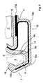
- FIG. 1 shows a cross section through a disc seal according to the invention for connection of an attachment 2 to a disc 3 of a motor vehicle, with a holding profile 1 comprising a holding leg 4 which rests against the surface 5 of the disc and a locking profile 7 for receiving a connecting element 8 of the attachment 2.
- the attachment 2 is here a water box cover 2.
- the holding profile 1 is formed such that for mounting the attachment 2, a lower force is required than for its disassembly.
- the locking profile 7 has two profile legs, which form an undercut clamping channel 6.
- the connecting element 8 engages behind the undercut clamping channel 6 in the installed state, whereby the connecting element 8 is held in the locking profile 7.
- an order of magnitude smaller force is required for mounting the attachment 2 than for disassembly.
- the disassembly force corresponding to the holding force of the attached attachment 2.
- the holding leg 4 facing first profile leg 9 has an interruption 13, which divides the first profile leg 9 in two subregions 9a, 9b.
- a connecting element 10 which connects the latching profile 7 with a distance from the first profile leg 9 at a distance a connecting portion 11 of the retaining leg 4.
- the distance between the upper portion 9a and the lower portion 9b increases. Since the locking profile 7 transmits the mounting forces on the connecting element 10, this acts as Rasthebelarm and the assembly forces are reduced.
- the length of the Rasthebelarmes, or directly linked to the mounting force can therefore be advantageously adjusted by adjusting the distance a to the required requirements.
- connection element 8 located in the undercut clamping channel 6 pulls up during removal of the attachment 2 the lower portion 9b in communication with the connecting element 10 and pushes it against the opposite upper portion 9a. The lower portion 9b is then supported on the upper portion 9a.
- the Rasthebelarm of the connecting element 10 is thereby shortened, or is not effective. Because of this advantageously takes the disassembly force, and thus directly linked to the holding force of the attachment 2 a much higher compared to the mounting force value.
- a connecting strip 12 is arranged, which is preferably designed as a double-sided adhesive tape and further preferably extends over the entire length of the retaining leg 4.
- the connecting strip 12 about the connecting strip 12, the retaining profile 1 with the rear surface 5 of the disc 3 of the motor vehicle permanently connected permanently. This ensures a simple, fast and cost-effective connection of the holding profile 1 to preferably the windscreen 3 of the motor vehicle.
- the connecting element 10 adjoins the connecting region 11 substantially at right angles.
- the connecting region 11 is arranged approximately in
- the central arrangement and the rectangular connection to the connecting element 10 ensure a uniformly distributed recording and initiation of the transferred assembly forces, and thus minimizing a negative for the adhesion of the connecting strip 12 peel load. Due to the low assembly forces and the described introduction of force in the connection region 11 can be dispensed with an additional support of the holding profile 1 on a body part.
- the connecting element 10 is formed in cross-section L-shaped.
- the interruption 13 of the first profile leg 9 has a slotted shape.
- the slotted shape is preferably provided in an extrusion tool of the holding profile 1, but can also be subsequently produced by a separation process, for example with a knife.
- To the holding profile 1 includes a profile element 14, which seals the area between the disc 3 and attachment 2.
- the profile element 14 is integrally formed on the retaining profile 1 and has an end portion 17 which consists of a more flexible in comparison with the material of the holding profile 1, rubber-elastic material.
- the end section 17 can be integrally formed on the profile element 14 by way of coextrusion, but can also be connected to the profile element 14 with another joining method, for example by gluing or welding.
- the profile element 14 and the end portion 17 are designed such that the profile element 14 terminates substantially flush both with the attachment outer surface W of the water box cover 2 and with the disc outer surface S of the disc 3.
- the profile element 14 and the retaining profile 1 have a soul of a stiff material 15, and a comparatively more flexible plastic sheath 16.
- the core 15 is made of a metallic material, preferably a foil of aluminum.
- the soul is constructed of two individual parts 15a, 15b, which have a different material thickness.
- a first aluminum profile 15a is provided with a material thickness of preferably about 0.4 mm.
- the region of the latching profile 7, the connecting element 10 and the profile element 14 has a second aluminum profile 15b with a material thickness of preferably approximately 0.2 mm.
- the aluminum profiles 15a, 15b are coated with a bonding agent and fixed by the extrusion of the plastic sheath 16 in their position to each other.
- the two aluminum profiles 15a, 15b can also be directly connected to each other, for example by gluing, welding or soldering.
- the assembly force of the attachment 2 can also be adjusted by the choice of material and the material thickness of the soul 15 of the holding profile 1.
- the retaining profile 1 and / or the plastic sheath 16 is preferably made of one or more plastics each having a suitable hardness, for example polypropylene (PP), polyvinyl chloride (PVC), acrylonitrile-butadiene-styrene (ABS), thermoplastic elastomers (TPE) or the like and / or from combinations thereof.
- PP polypropylene
- PVC polyvinyl chloride
- ABS acrylonitrile-butadiene-styrene
- TPE thermoplastic elastomers
- FIG. 2 shows a cross section of another embodiment of the in Fig. 1 shown disc seal.
- additional recesses 19a, 19b which extend in the longitudinal direction of the holding profile 1 and over whose distribution, number and notch radius the rigidity of the connecting element 10 can be adjusted.
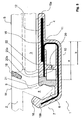
- an additional support member 20 is provided, which is arranged between the holding profile 7 and the connecting portion 11 and also has an interruption 22.
- the support element 20 is spaced from the connection region 11 at a distance b.
- an enlargement of the distance between the subregions of the support element 20a, 20b likewise takes place.
- the support element 20 and the interrupted first profile leg 9 can advantageously be matched to one another such that the disassembly of the attachment the Ab neutrallementteil Jardine 20a, 20b abut each other before the portions 9a, 9b of the profile leg 9 abut each other.
- About the distance b can then be advantageously set the disassembly force by the then acting Rasthebelarm during disassembly against the arrangement in FIG.
- the support element 20 and the profile leg 9 can advantageously also be coordinated with each other so that the respective portions 9a, 9b, 20a, 20b abut each other simultaneously to uniformly absorb the occurring disassembly forces and pass it into the disc 3.
- a sealing element 18 is arranged on the water box cover 2, which closes the attachment part outer surface W of the water box cover 2 with the disc outer surface S of the disc 3 is substantially flush and / or seals.
- the sealing element 18 may be molded onto the water box cover 2 by injection molding, but may also be glued or welded.
- the sealing member 18 is preferably made of a thermoplastic elastomer (TPE), a sponge rubber or other suitable material.
- FIG. 4 shows a cross-section through a further embodiment of the disc seal with a filled with a comparison of the holding member elastic material interruption 13 of the profile leg 9 of the holding profile 1.
- the elastic material forms an expansion element 21, which preferably integrally connected to the subregions 9a, 9b of the profile leg 9 is.
- the expansion element 21 is advantageously introduced by way of coextrusion in the interruption 13 of the profile leg 9, but may also be glued or welded, for example.
- the material of the expansion element 21, which is more elastic than the material of the retaining profile 1, furthermore allows a deflection of the connecting element 10 and, associated therewith, the reduction of the assembly force by the present latching lever arm due to the greater extensibility.
- a seal of the enclosed by the profile leg 9, the connecting element 10 and the retaining leg 4 cavity is also ensured.
- the mounting force can be additionally adjusted specifically.
- the material of the expansion element 21 may be a foamed material or, more preferably, a material having a high stretchability.
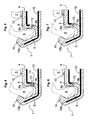
- FIGS. 5 to 7 each show a cross section through an embodiment in which the mutually facing portions 9a, 9b of the profile leg 9 each have a mutually complementary contour.
- the complementary contours preferably interlock with one another such that a buckling and / or slipping of the two subregions 9a, 9b of the first profile limb 9 is prevented by the pressure loading on the subregions 9a, 9b occurring during disassembly.
- the disassembly force is uniformly and surely transmitted from the lower portion 9b to the upper portion 9a.
- the support element portions 20a, 20b of the in FIG. 3 described support member 20 have corresponding cross-sectional complementary contours.
- FIG. 8 shows a cross section through a further embodiment of the disc seal with a filled with an elastic material, here very wide trained interruption 13 of the profile leg 9 of the holding profile 1.
- the more elastic compared to the material of the holding profile 1 material in turn forms an expansion element 21.
- the expansion element 21 is advantageously introduced by way of coextrusion in the interruption 13 of the profile leg 9, but can also be glued or welded, for example.
- the material of the expansion element may be a foamed material or more preferably a material having a high stretchability.
- the expansion element 21 adapts to the outer contour of the connection element 8. In addition to a sealing of the clamping channel 6, an additional fixation of the connecting element 8 in the clamping channel 6 can be achieved.
- the Hatteprofil 1 in turn, between the expansion element 21 and the connecting portion 11, a support member 20 which has a break 22.
- About the distance b can advantageously be set the disassembly force by the acting Rasthebelarm during disassembly against the arrangement in FIG. 1 is adjusted.
- the disassembly force increases according to the invention compared to the assembly force by shortening the Rasthebelarms of the connecting element 10 as soon as the Ab neutrallementteil Schemee 20a, 20b abut each other.
- FIG. 9 shows a cross section through an embodiment of the disc seal with a single profile leg and an additional support member 20.
- the disc seal 1 has no first profile leg 9.
- the shortening of the effective lever arm of the connecting element 10 takes place during disassembly via the support element 20, which is arranged between the second profile leg, which simultaneously forms the latching profile 7, and the connecting region 11.
Landscapes
- Engineering & Computer Science (AREA)
- Mechanical Engineering (AREA)
- Gasket Seals (AREA)
- Seal Device For Vehicle (AREA)
Description
- Die vorliegende Erfindung betrifft eine Scheibenabdichtung zum Anschluss eines Anbauteils an eine Scheibe eines Kraftfahrzeuges, mit einem Halteprofil aufweisend einen Halteschenkel, der an der Oberfläche der Scheibe anliegt und einem Rastprofil zur Aufnahme eines Anschlusselementes des Anbauteils.
- Aus der
DE 10 2004 044 598 A1 ist eine Scheibenabdichtung mit den eingangs beschriebenen Merkmalen bekannt. Das Halteprofil weist eine Hinterschneidung zur Aufnahme eines Fortsatzes oder einer Raste einer Wasserkastenabdeckung auf. Ferner ist eine Verstärkungsseele vorgesehen. In den Krümmungen der Seele sind Kerben vorgesehen, deren Gestaltung die Einstellung der gewünschten Montage- bzw. Demontagekraft ermöglicht. Dabei können jedoch die Montagekraft und die Demontagekraft nicht unabhängig voneinander, sondern nur gemeinsam konstruktiv festgelegt werden. - In der gattungsgemäβen
EP 1 280 675 B1 ist ein Profilkörper offenbart, der mit Versteifungseinlagen versehen ist und zur Aufnahme einer einspringenden Rippe einer Wasserkastenabdeckung eine Hinterschneidung aufweist. Der Profilkörper ist mit einem elastischen Stützschenkel versehen, der die Außenflächen der Scheiben-Unterkante und des oberen Rands der Wasserkastenabdeckung im Wesentlichen bündig abschließt. Das Dichtungsprofil liegt mittels einer selbstklebenden Haftschicht von hinten an der Frontscheibe an. Der Profilkörper muss entgegen der wirkenden Montagekraft rückseitig über eine Pufferleiste an einem Karosseriebestandteil abgestützt werden. Soll eine hohe Demontagekraft erreicht werden, müssen entsprechend hohe Montagekräfte angewendet werden, die eine Abstützung des Profilkörpers an dem Karosseriebestandteil zwingend erforderlich machen. Die Haftschicht kann ohne Abstützung die auftretenden Montagekräfte nicht aufnehmen, da sich der Profilkörper bei der Montage der Wasserkastenabdeckung von der Frontscheibe lösen würde. Eine geringe Montagekraft, bei gleichzeitiger hoher Demontagekraft ist nicht erzielbar. - Vor diesem Hintergrund liegt der Erfindung die Aufgabe zugrunde, eine Scheibenabdichtung mit den eingangs beschriebenen Merkmalen anzugeben, die eine leichte Montierbarkeit eines Anbauteils bei gleichzeitig hoher Haltekraft ermöglicht.
- Erfindungsgemäß wird diese Aufgabe mit den Merkmalen von Anspruch 1 gelöst.
- Wie aus
EP 1 280 675 B1 bekannt, weist das Rastprofil mindestens zwei Profilschenkel auf die gemeinsam einen hinterschnittenen Klemmkanal bilden. Erfindungsgemäβ weist der dem Halteschenkel zugewandte erste Profilschenkel eine Unterbrechung auf, die den ersten Profilschenkel in zwei Teilbereiche unterteilt. Zusätzliches ist ein Verbindungselement vorgesehen, das das Rastprofil mit einem vom ersten Profilschenkel beabstandeten Verbindungsbereich des Halteschenkels verbindet. Ferner steht der untere Teilbereich der zwei Teilbereiche in Verbindung mit diesem Verbindungselement. Bei der Montage des Anbauteils erfolgt so eine Vergrößerung des Abstandes zwischen den Teilbereichen, während bei einer Demontage des Anbauteils die Teilbereiche sich aneinander annähern. Das Rastprofil überträgt die Montagekräfte auf das Verbindungselement. Das Verbindungselement wirkt als Rasthebelarm und die Montagekräfte werden reduziert. Über die Veränderung des Abstandes von Rastprofilschenkel und Verbindungsbereich kann die Länge des Verbindungselementes, und damit die Montagekraft in einem weiten Bereich konstruktiv eingestellt werden. Im Gegensatz dazu vergrößert sich bei der Demontage des Anbauteils die Demontagekraft, sobald z.B. die Teilbereiche aneinander anliegen. Der Rasthebelarm des Verbindungselements verkürzt sich, bzw. ist gar nicht mehr wirksam. Die Montage- und Demontagekräfte können in einem weiten Bereich, und zwar völlig unabhängig voneinander, einfach und variabel eingestellt werden. Vorteilhafterweise ist die Geometrie des Klemmkanals derart gestaltet, dass die durch die Unterbrechung des Profilschenkels ermöglichte Auslenkung des Rastprofils den hinterschnittenen Bereich des Klemmkanals verringert und das Anschlusselement mit einer geringeren Kraft das Rastprofil hintergreifen kann. - Der Halteschenkel der Scheibenabdichtung kann ein an die Oberfläche der Scheibe angrenzendes Klebeband oder eine an die Oberfläche der Scheibe angrenzende Klebstoffschicht aufweisen. Mit dem Klebeband kann der Halteschenkel des Halteprofils schnell und einfach mit der Oberfläche der Scheibe verbunden werden. Es kann auch eine Silikonschicht oder auch jedes andere geeignete Fügeverfahren zum Verbinden des Halteprofils mit der Scheibe des Kraftfahrzeuges vorgesehen sein. Aufgrund der geringen Montagekräfte ist eine rohbauseitige hintere Abstützung der Scheibenabdichtung an der Fahrzeugkarosserie, wie bei
EP 1 280 675 B1 beschrieben, nicht erforderlich. Auf das teure und aufwendige Vergießen des Halteprofils mit z.B. einem Klebstoff kann ebenfalls verzichtet werden. Durch die erfindungsgemäße Scheibenabdichtung kann dieser zusätzliche Aufwand vermieden werden, so dass sich ein geringerer Konstruktionsaufwand, eine größere Designfreiheit und eine Reduzierung der Kosten- und der Montagezeiten ergibt. - Das Verbindungselement der Scheibenabdichtung kann an den Verbindungsbereich im Wesentlichen rechtwinklig anschließen. Die bei der Montage des Anbauteils über den Rasthebelarm des Verbindungselementes übertragenen Montagekräfte werden dann im Wesentlichen senkrecht auf den Kontaktbereich von Halteschenkel und Oberfläche der Scheibe übertragen. Durch den rechtwinkligen Anschluss an den Verbindungsbereich führen die eingeleiteten Montagekräfte zu keiner, oder nur einer geringen, Schälbeanspruchung des Klebebandes, bzw. der Klebstoffschicht.
- Der Verbindungsbereich der Scheibenabdichtung ist vorteilhafterweise in etwa in der Mitte des Halteschenkels angeordnet. Die bei der Montage auftretenden, und über das Verbindungselement in den Verbindungsbereich eingeleiteten, Montagekräfte können vorteilhafterweise von dem Halteschenkel gleichmäßig auf den Kontaktbereich zur Oberfläche der Scheibe übertragen und verteilt werden.
- Das Verbindungselement der Scheibenabdichtung ist vorteilhafterweise im Querschnitt im Wesentlichen L-förmig ausgebildet. Diese Geometrie ermöglicht zum einen den rechtwinkligen Anschluss an den Halteschenkel, und zum anderen die kürzeste Verbindung mit dem Rastprofil. Alternativ hierzu kann es vorteilhaft sein, dass das Verbindungselement eine im Wesentlichen gebogene Form aufweist, über deren Geometrieanpassung die Federsteifigkeit des Verbindungselementes, und somit ebenfalls die Montagekraft angepasst werden kann.
- Die einander zugewandten Ränder der Teilbereiche des Profilschenkels können vorteilhafterweise im Querschnitt eine zueinander komplementäre Kontur aufweisen. Die zueinander komplementären Konturen greifen vorzugsweise so ineinander ein, dass ein Ausknicken und/oder aneinander Abgleiten der beiden Teilbereiche des Profilschenkels durch die bei der Demontage auftretende Druckbelastung auf die beiden Teilbereiche zuverlässig verhindert wird. Zudem wird die Demontagekraft gleichmäßig und sicher in die Scheibe übertragen.
- Die Unterbrechung des dem Halteschenkel zugewandte ersten Profilschenkels kann eine geschlitzte Form aufweisen.
- Innerhalb der Unterbrechung des Profilschenkels kann ein im Vergleich zum Halteprofil elastischeres Material angeordnet sein. Das gegenüber dem Material des Halteprofils elastischere Material in der Unterbrechung ermöglicht durch seine größere Dehnbarkeit weiterhin eine Auslenkung des Rasthebelarmes des Verbindungselementes. Vorteilhafterweise ist zudem eine Abdichtung des von dem geteilten Profilschenkel, dem Verbindungselement und dem Halteschenkel eingeschlossenen Hohlraumes gewährleistet. Über die Elastizität des gewählten Materials in der gefüllten Unterbrechung kann vorteilhafterweise die Montagekraft zusätzlich eingestellt und angepasst werden. Vorzugsweise kann das Material in der gefüllten Unterbrechung ein geschäumtes Material, wie z.B. ein Moosgummi, sein oder weiter vorzugsweise ein Material mit einer hohen Dehnfähigkeit.
- Zwischen dem Rastprofil und dem Verbindungsbereich kann mindestens ein Abstützelement angeordnet sein, das ebenfalls eine Unterbrechung aufweist. Das Abstützelement und der Profilschenkel können vorteilhafterweise so aufeinander abgestimmt sein, dass die Teilbereiche des Abstützelementes aneinander anliegen, bevor die Teilbereiche des Profilschenkels aneinander anliegen. Über den Abstand zwischen Abstützelement und Verbindungsbereich kann die Demontagekraft eingestellt werden, indem eine Variation des Abstandes den bei der Demontage wirkenden Rasthebelarm verändert. Das Abstützelement und der Profilschenkel können weiter vorteilhafterweise so aufeinander abgestimmt sein, dass die jeweiligen Teilbereiche gleichzeitig aneinander anliegen, so dass die auftretenden Demontagekräfte gleichmäßig von Profilschenkel und Abstützelement aufgenommen und in die Scheibe übergeleitet werden. Hierbei kann es zudem weiter von Vorteil sein nicht ein einziges Abstützelement, sondern mehrere Abstützelemente vorzusehen.
- Eine vorteilhafte Weiterbildung der Erfindung sieht vor, auf den ersten Profilschenkel ganz zu verzichten, und die bei der Demontage auftretenden Kräfte allein über Abstützelemente aufzunehmen. Das Rastprofil weist in diesem Fall lediglich einen einzigen Profilschenkel auf.
- Die Scheibenabdichtung kann vorteilhafterweise ein an das Halteprofil anschließendes Profilelement aufweisen, das den Bereich zwischen Scheibe und Anbauteil abdichtet. Vorzugsweise kann das Profilelement einstückig an das Halteprofil angeformt sein und weiter vorzugsweise einen Endabschnitt aus einem im Vergleich mit dem Material des Halteprofils flexibleren Material aufweisen. Das Profilelement und/oder der Endabschnitt schließt vorteilhafterweise mit den Außenflächen des Anbauteils und der Scheibe bündig ab.
- Das Profilelement und/oder das Halteprofil der Scheibenabdichtung kann mindestens eine aus einem steiferen Material bestehenden Seele und eine im Vergleich dazu flexiblere Kunststoffummantelung aufweisen. Die Kunststoffummantelung kann im Wege des Extrudierens oder des Spritzgießens auf die Seele aufgebracht sein. Die Seele kann aus mindestens zwei Einzelteilen zusammengesetzt sein. Durch die Kombination von mehreren einfachen Geometrien lassen sich so kostengünstig komplexere Geometrien herstellen. Vorteilhafterweise besteht die Seele aus einem metallischen Material, vorzugsweise aus einer Aluminiumlegierung oder aus rostfreiem Edelstahl oder aus Titan oder einer Titanlegierung oder aus Federstahl oder aus Baustahl. Über die Auswahl des metallischen Materials und über die Materialstärke der Seele kann ebenfalls die Montagekraft, bzw. Demontagekraft über die sich ergebende Steifigkeit des gesamten Halteprofils oder von Teilbereichen des Halteprofils beeinflusst werden. Es kann zudem von Vorteil sein, durch zusätzliche Ausnehmungen in den Krümmungsbereichen der Seele des Halteprofils, die sich in Längsrichtung des Profilkörpers erstrecken, die Steifigkeit des Halteprofils anzupassen.
- Gegenstand der Erfindung ist auch eine Anordnung mit einer erfindungsgemäßen Scheibenabdichtung nach einem der Ansprüche 13 bis 15.
- Im Folgenden wird die Erfindung anhand einer lediglich ein Ausführungsbeispiel darstellenden Zeichnung erläutert. Es zeigen schematisch:
- Fig. 1
- einen Querschnitt durch eine erfindungsgemäße Scheibenabdichtung
- Fig. 2
- einen Querschnitt einer weiteren Ausführungsform der in
Fig. 1 gezeigten Scheibenabdichtung mit zusätzlichen Ausnehmungen im Krümmungsbereich der Seele des Halteprofils - Fig. 3
- einen Querschnitt durch eine weitere Ausführungsform der Scheibenabdichtung mit einem zusätzlichen Abstützelement
- Fig. 4
- einen Querschnitt durch eine weitere Ausführungsform der Scheibenabdichtung mit einer mit einem elastischen Material gefüllten Unterbrechung des Profilschenkels des Halteprofils
- Fig. 5
- einen Querschnitt durch eine Ausführungsform der zueinander komplementären Kontur der einander zugewandten Teilbereiche des Profilschenkels
- Fig. 6
- einen Querschnitt durch eine andere Ausführungsform der zueinander komplementären Kontur der einander zugewandten Teilbereiche des Profil
- Fig. 7
- einen Querschnitt durch eine weitere Ausführungsform der zueinander komplementären Kontur der einander zugewandten Teilbereiche des Profilschenkels
- Fig. 8
- einen Querschnitt durch eine weitere Ausführungsform der Scheibenabdichtung mit einer mit einem elastischen Material gefüllten breiten Unterbrechung des Profilschenkels des Halteprofils
- Fig. 9
- einen Querschnitt durch eine Ausführungsform der Scheibenabdichtung mit einem einzelnen Profilschenkel und einem zusätzlichen Abstützelement
- Die
Figur 1 zeigt einen Querschnitt durch eine erfindungsgemäße Scheibenabdichtung zum Anschluss eines Anbauteils 2 an eine Scheibe 3 eines Kraftfahrzeuges, mit einem Halteprofil 1 aufweisend einen Halteschenkel 4, der an der Oberfläche 5 der Scheibe anliegt und einem Rastprofil 7 zur Aufnahme eines Anschlusselementes 8 des Anbauteils 2. - Das Anbauteil 2 ist hier eine Wasserkastenabdeckung 2. Das Halteprofil 1 ist derart ausgebildet, dass zur Montage des Anbauteils 2 eine geringere Kraft erforderlich ist als zu dessen Demontage. Das Rastprofil 7 weist zwei Profilschenkel auf, die einen hinterschnittenen Klemmkanal 6 bilden. Das Anschlusselement 8 hintergreift im eingebauten Zustand den hinterschnittenen Klemmkanal 6, wodurch das Anschlusselement 8 im Rastprofil 7 gehalten wird. Bei dem erfindungsgemäßen Halteprofil 1 ist zur Montage des Anbauteils 2 eine um eine Größenordnung geringere Kraft erforderlich ist als zur Demontage. Der Demontagekraft entspricht die Haltekraft des angeschlossenen Anbauteils 2. Der dem Halteschenkel 4 zugewandte erste Profilschenkel 9 weist eine Unterbrechung 13 auf, die den ersten Profilschenkel 9 in zwei Teilbereiche 9a, 9b unterteilt. Zusätzliches ist ein Verbindungselement 10 vorgesehen, das das Rastprofil 7 mit einem vom ersten Profilschenkel 9 in einem Abstand a beabstandeten Verbindungsbereich 11 des Halteschenkels 4 verbindet. Bei der Montage des Anbauteils 2 vergrößert sich der Abstand zwischen dem oberen Teilbereich 9a und dem unteren Teilbereich 9b. Da das Rastprofil 7 die Montagekräfte auf das Verbindungselement 10 überträgt, wirkt dieses als Rasthebelarm und die Montagekräfte werden reduziert. Die Länge des Rasthebelarmes, bzw. direkt verknüpft die Montagekraft kann daher vorteilhafterweise über die Einstellung des Abstandes a an die benötigten Anforderungen angepasst werden. Bei einer Demontage des Anbauteils 2 nähern die Teilbereiche 9a, 9b sich aneinander an. Das in dem hinterschnittenen Klemmkanal 6 befindliche Anschlusselement 8 zieht bei der Demontage des Anbauteil 2 den mit dem Verbindungselement 10 in Verbindung stehenden unteren Teilbereich 9b nach oben und drückt diesen gegen den gegenüberliegenden oberen Teilbereich 9a. Der untere Teilbereich 9b stützt sich dann an dem oberen Teilbereich 9a ab. Der Rasthebelarm des Verbindungselements 10 verkürzt sich dadurch, bzw. ist gar nicht wirksam. Aufgrund dessen nimmt vorteilhafterweise die Demontagekraft, und damit direkt verknüpft die Haltekraft des Anbauteils 2 einen im Vergleich zur Montagekraft wesentlich höheren Wert an. An dem Halteschenkel 4 ist ein Verbindungsstreifen 12 angeordnet, der vorzugsweise als doppelseitiges Klebeband ausgebildet ist und sich weiter vorzugsweise über die gesamte Länge des Halteschenkels 4 erstreckt. Über den Verbindungsstreifen 12 wird das Halteprofil 1 mit der rückseitigen Oberfläche 5 der Scheibe 3 des Kraftfahrzeuges permanent fest verbunden. Dies gewährleistet eine einfache, schnelle und kostengünstige Anbindung des Halteprofils 1 an vorzugsweise der Frontscheibe 3 des Kraftfahrzeuges. Das Verbindungselement 10 schließt an den Verbindungsbereich 11 im Wesentlichen rechtwinklig an. Der Verbindungsbereich 11 ist in etwa in der Mitte des Halteschenkels 4 angeordnet.
- Die mittige Anordnung und der rechtwinklige Anschluss an das Verbindungselement 10 gewährleisten eine gleichmäßig verteilte Aufnahme und Einleitung der übertragenen Montagekräfte, und somit eine Minimierung einer für die Haftung des Verbindungsstreifens 12 negativen Schälbelastung. Aufgrund der geringen Montagekräfte und der beschriebenen Krafteinleitung in den Verbindungsbereich 11 kann auf eine zusätzliche Abstützung des Halteprofils 1 an einem Karosserieteil verzichtet werden. Das Verbindungselement 10 ist im Querschnitt L-förmig ausgebildet. Die Unterbrechung 13 des ersten Profilschenkels 9 weist eine geschlitzte Form auf. Die geschlitzte Form ist vorzugsweise in einem Extrusionswerkzeug des Halteprofils 1 vorgesehen, kann aber auch nachträglich durch einen Trennvorgang, z.B. mit einem Messer hergestellt werden. An das Halteprofil 1 schließt ein Profilelement 14 an, das den Bereich zwischen Scheibe 3 und Anbauteil 2 abdichtet. Das Profilelement 14 ist einstückig an das Halteprofil 1 angeformt und weist einen Endabschnitt 17 auf, der aus einem im Vergleich mit dem Material des Halteprofils 1 flexibleren, gummielastischen Material besteht. Der Endabschnitt 17 kann im Wege der Coextrusion an das Profilelement 14 angeformt sein, kann aber auch mit einem anderen Fügeverfahren, z.B. durch Kleben oder Schweißen mit dem Profilelement 14 verbunden sein. Das Profilelement 14 und der Endabschnitt 17 sind derart gestaltet, dass das Profilelement 14 sowohl mit der Anbauteilaußenfläche W der Wasserkastenabdeckung 2 als auch mit der Scheibenaußenfläche S der Scheibe 3 im Wesentlichen bündig abschließt. Das Profilelement 14 und das Halteprofil 1 weisen eine aus einem steifen Material bestehenden Seele 15, und eine im Vergleich dazu flexiblere Kunststoffummantelung 16 auf. Die Seele 15 besteht aus einem metallischen Material, vorzugsweise einer Folie aus Aluminium. Die Seele ist aus zwei Einzelteilen 15a, 15b aufgebaut, die eine unterschiedliche Materialstärke aufweisen. Im Bereich des Halteschenkels 4 ist ein erstes Aluminiumprofil 15a mit einer Materialstärke von vorzugsweise ca. 0,4 mm vorgesehen. Der Bereich des Rastprofils 7, des Verbindungselementes 10 und des Profilelementes 14 weist ein zweites Aluminiumprofil 15b mit einer Materialstärke von vorzugsweise ca. 0,2 mm auf. Die Aluminiumprofile 15a, 15b sind mit einem Haftvermittler überzogen und durch das Aufextrudieren der Kunststoffummantelung 16 in Ihrer Lage zueinander fixiert. Die beiden Aluminiumprofile 15a, 15b können auch direkt miteinander verbunden sein, durch z.B. Kleben, Schweißen oder Löten. Vorteilhafterweise kann durch die Wahl des Materials und der Materialstärke der Seele 15 des Halteprofils 1 die Montagekraft des Anbauteils 2 ebenfalls eingestellt werden.
- Das Halteprofil 1 und/oder die Kunststoffummantelung 16 besteht vorzugsweise aus einem oder mehreren Kunststoffen jeweils geeigneter Härte, beispielsweise Polypropylen (PP), Polyvinylchlorid (PVC), Acrylnitril-Butadien-Styrol (ABS), thermoplastischen Elastomeren (TPE) oder dergleichen und/oder aus Kombinationen davon.
- Die
Figur 2 zeigt einen Querschnitt einer weiteren Ausführungsform der inFig. 1 gezeigten Scheibenabdichtung. In den Krümmungsbereichen der Seele 15b des Verbindungselements 10 befinden sich zusätzliche Ausnehmungen 19a, 19b, die sich in Längsrichtung des Halteprofils 1 erstrecken und über deren Verteilung, Anzahl und Kerbradius die Steifigkeit des Verbindungselementes 10 angepasst werden kann. - In
Figur 3 ist ein zusätzliches Abstützelement 20 vorgesehen, das zwischen dem Halteprofil 7 und dem Verbindungsbereich 11 angeordnet ist und ebenfalls eine Unterbrechung 22 aufweist. Das Abstützelement 20 ist von dem Verbindungsbereich 11 im Abstand b beabstandet. Bei der Montage des Anbauteils 2 erfolgt ebenfalls eine Vergrößerung des Abstandes zwischen den Teilbereichen des Abstützelements 20a, 20b. Das Abstützelement 20 und der unterbrochene erste Profilschenkel 9 können vorteilhafterweise so aufeinander abgestimmt sein, dass bei der Demontage des Anbauteils die Abstützelementteilbereiche 20a, 20b aneinander anliegen, bevor die Teilbereiche 9a, 9b des Profilschenkels 9 aneinander anliegen. Über den Abstand b kann dann vorteilhafterweise die Demontagekraft eingestellt werden, indem der dann wirkende Rasthebelarm bei der Demontage gegenüber der Anordnung inFigur 1 variiert wird. Das Abstützelement 20 und der Profilschenkel 9 können vorteilhafterweise auch so aufeinander abgestimmt sein, dass die jeweiligen Teilbereiche 9a, 9b, 20a, 20b gleichzeitig aneinander anliegen, um die auftretenden Demontagekräfte gleichmäßig aufzunehmen und in die Scheibe 3 überzuleiten. Hierzu kann es von Vorteil sein, nicht ein einziges Abstützelement 20, sondern mehrere Abstützelemente 20 vorzusehen. Ferner ist an der Wasserkastenabdeckung 2 ein Abdichtungselement 18 angeordnet, das die Anbauteilaußenfläche W der Wasserkastenabdeckung 2 mit der Scheibenaußenfläche S der Scheibe 3 im Wesentlichen bündig abschließt und/oder abdichtet. Das Abdichtelement 18 kann im Spritzgießverfahren an die Wasserkastenabdeckung 2 angeformt sein, kann aber auch angeklebt oder geschweißt sein. Das Abdichtelement 18 besteht bevorzugt aus einem thermoplastischen Elastomer (TPE), einem Moosgummi oder einem anderen geeigneten Material. - Die
Figur 4 zeigt einen Querschnitt durch eine weitere Ausführungsform der Scheibenabdichtung mit einer mit einem im Vergleich zum Halteprofil elastischeren Material gefüllten Unterbrechung 13 des Profilschenkels 9 des Halteprofils 1. Das elastische Material bildet ein Dehnelement 21, das vorzugsweise stoffschlüssig mit den Teilbereichen 9a, 9b des Profilschenkels 9 verbunden ist. Das Dehnelement 21 ist vorteilhafterweise im Wege der Coextrusion in die Unterbrechung 13 des Profilschenkels 9 eingebracht, kann aber auch z.B. eingeklebt oder geschweißt sein. Das gegenüber dem Material des Halteprofils 1 elastischere Material des Dehnelements 21 ermöglicht durch die größere Dehnbarkeit weiterhin eine Auslenkung des Verbindungselementes 10 und damit verbunden die Reduzierung der Montagekraft durch den vorliegenden Rasthebelarm. Vorteilhafterweise ist zudem eine Abdichtung des von dem Profilschenkel 9, dem Verbindungselement 10 und dem Halteschenkel 4 eingeschlossenen Hohlraumes gewährleistet. Vorteilhafterweise kann insbesondere über die gewählte Elastizität des Materials des Dehnelements 21 die Montagekraft zusätzlich gezielt eingestellt werden. Das Material des Dehnelements 21 kann ein geschäumtes Material sein oder weiter vorzugsweise ein Material mit einer hohen Dehnfähigkeit sein. - Die
Figuren 5 bis 7 zeigen jeweils einen Querschnitt durch eine Ausführungsform, bei der die einander zugewandten Teilbereiche 9a, 9b des Profilschenkels 9 jeweils eine zueinander komplementäre Kontur besitzen. In denFiguren 5 bis 7 sind bevorzugte Ausführungsformen dieser komplementären Konturen dargestellt. Die komplementären Konturen greifen vorzugsweise so ineinander ein, dass ein Ausknicken und/oder aneinander Abgleiten der beiden Teilbereiche 9a, 9b des ersten Profilschenkels 9 durch die bei der Demontage auftretende Druckbelastung auf die Teilbereiche 9a, 9b verhindert wird. Zudem wird die Demontagekraft gleichmäßig und sicher von dem unteren Teilbereich 9b auf den oberen Teilbereich 9a übertragen. Zudem kann es vorteilhaft sein, dass die Abstützelementteilbereiche 20a, 20b des in derFigur 3 beschriebenen Abstützelementes 20 entsprechende im Querschnitt zueinander komplementäre Konturen aufweisen. - Die
Figur 8 zeigt einen Querschnitt durch eine weitere Ausführungsform der Scheibenabdichtung mit einer mit einem elastischen Material gefüllten, hier sehr breit ausgebildeten Unterbrechung 13 des Profilschenkels 9 des Halteprofils 1. Das im Vergleich zum Material des Halteprofils 1 elastischere Material bildet wiederum ein Dehnelement 21. Das Dehnelement 21 ist vorteilhafterweise im Wege der Coextrusion in die Unterbrechung 13 des Profilschenkels 9 eingebracht, kann aber auch z.B. eingeklebt oder geschweißt sein. - Das gegenüber dem Material des Halteprofils 1 elastischere Material des Dehnelements 21 ermöglicht durch die größere Dehnbarkeit weiterhin eine Auslenkung des Verbindungselementes 10, und damit verbunden eine Reduzierung der Montagekraft. Vorzugsweise kann das Material des Dehnelements ein geschäumtes Material sein oder weiter vorzugsweise ein Material mit einer hohen Dehnfähigkeit sein. Vorteilhafterweise passt sich das Dehnelement 21 an die Außenkontur des Anschlusselementes 8 an. Neben einer Abdichtung des Klemmkanals 6 kann so eine zusätzliche Fixierung des Anschlusselementes 8 in dem Klemmkanal 6 erreicht werden. Das Hatteprofil 1 weist zwischen dem Dehnelement 21 und dem Verbindungsbereich 11 wiederum ein Abstützelement 20 auf, das eine Unterbrechung 22 aufweist. Über den Abstand b kann vorteilhafterweise die Demontagekraft eingestellt werden, indem der wirkende Rasthebelarm bei der Demontage gegenüber der Anordnung in
Figur 1 angepasst wird. Die Demontagekraft vergrößert sich erfindungsgemäß gegenüber der Montagekraft durch die Verkürzung des Rasthebelarms des Verbindungselements 10, sobald die Abstützelementteilbereiche 20a, 20b aneinander anliegen. - Die
Figur 9 zeigt einen Querschnitt durch eine Ausführungsform der Scheibenabdichtung mit einem einzelnen Profilschenkel und einem zusätzlichen Abstützelement 20. Die Scheibenabdichtung 1 weist keinen ersten Profilschenkel 9 auf. Die Verkürzung des wirksamen Hebelarmes des Verbindungselementes 10 erfolgt bei der Demontage über das Abstützelement 20, das zwischen dem zweiten Profilschenkel, der gleichzeitig das Rastprofil 7 bildet, und dem Verbindungsbereich 11 angeordnet ist.
Claims (14)
- Scheibenabdichtung zum Anschluss eines Anbauteils (2) an eine Scheibe (3) eines Kraftfahrzeuges, mit einem Halteprofil (1) aufweisend- einen Halteschenkel (4), der an der Oberfläche (5) der Scheibe (3) anliegt und- einem Rastprofil (7) zur Aufnahme eines Anschlusselementes (8) des Anbauteils (2),wobei das Rastprofil (7) mindestens zwei Profilschenkel aufweist, die gemeinsam einen hinterschnittenen Klemmkanal (6) bilden und wobei das Halteprofil (1) derart ausgebildet ist, dass zur Montage des Anbauteils (2) eine geringere Kraft erforderlich ist als zur Demontage,
dadurch gekennzeichnet, dass
ein Verbindungselement (10) vorgesehen ist, das das Rastprofil (7) mit einem von einem ersten Profilschenkel (9) beabstandeten Verbindungsbereich (11) des Halteschenkels (4) verbindet, dass der dem Halteschenkel (4) zugewandte erste Profilschenkel (9) eine Unterbrechung (13) aufweist, die den ersten Profilschenkel (9) in zwei Teilbereiche (9a, 9b) unterteilt und, dass der untere Teilbereich (9b) der zwei Teilbereiche (9a, 9b) in Verbindung mit dem Verbindungselement (10) steht, so dass bei der Montage des Anbauteils (2) eine Vergrößerung des Abstandes zwischen den Teilbereichen (9a, 9b) erfolgt, während bei einer Demontage des Anbauteils (2) die Teilbereiche (9a, 9b) sich aneinander annähern. - Scheibenabdichtung nach Anspruch 1, dadurch gekennzeichnet, dass der Halteschenkel (4) ein an die Oberfläche (5) der Scheibe (3) angrenzendes Klebeband (12) oder eine an der Oberfläche (5) der Scheibe (3) angrenzende Klebstoffschicht (12) aufweist.
- Scheibenabdichtung nach einem der Ansprüche 1 oder 2, dadurch gekennzeichnet, dass das Verbindungselement (10) an den Verbindungsbereich (11) im Wesentlichen rechtwinklig anschließt.
- Scheibenabdichtung nach einem der Ansprüche 1 bis 3, dadurch gekennzeichnet, dass der Verbindungsbereich (11) in etwa in der Mitte des Halteschenkels (4) angeordnet ist.
- Scheibenabdichtung nach einem der Ansprüche 1 bis 4, dadurch gekennzeichnet, dass das Verbindungselement (10) im Querschnitt im Wesentlichen L-förmig ausgebildet ist.
- Scheibenabdichtung nach einem der Ansprüche 1 bis 5, dadurch gekennzeichnet, dass die einander zugewandten Ränder der Teilbereiche (9a, 9b) im Querschnitt eine zueinander komplementäre Kontur aufweisen.
- Scheibenabdichtung nach einem der Ansprüche 1 bis 6, dadurch gekennzeichnet, dass die Unterbrechung (13) eine geschlitzte Form aufweist.
- Scheibenabdichtung nach einem der Ansprüche 1 bis 7, dadurch gekennzeichnet, dass innerhalb der Unterbrechung (13) ein im Vergleich zum Halteprofil (1) elastischeres Material angeordnet ist.
- Scheibenabdichtung nach einem der Ansprüche 1 bis 8, dadurch gekennzeichnet, dass zwischen dem Rastprofil (7) und dem Verbindungsbereich (11) mindestens ein Abstützelement (20) angeordnet ist, das eine Unterbrechung (22) aufweist.
- Scheibenabdichtung nach einem der Ansprüche 1 bis 9, dadurch gekennzeichnet, dass an das Halteprofil (1) ein Profilelement (14) anschließt, das den Bereich zwischen Scheibe (3) und Anbauteil (2) abdichtet.
- Scheibenabdichtung nach einem der Ansprüche 1 bis 10, dadurch gekennzeichnet, dass das Profilelement (14) und/oder das Halteprofil (1) mindestens eine aus einem steifen Material bestehenden Seele (15) und eine im Vergleich dazu flexiblere Kunststoffummantelung (16) aufweist.
- Anordnung mit einer Scheibenabdichtung nach einem der Ansprüche 1 bis 11 und einer Scheibe (3) eines Kraftfahrzeuges.
- Anordnung mit einer Scheibenabdichtung nach einem der Ansprüche 1 bis 11 und einem Anbauteil (2).
- Anordnung nach Anspruch 13, wobei das Anbauteil (2) als Wasserkastenabdeckung ausgebildet ist.
Priority Applications (1)
| Application Number | Priority Date | Filing Date | Title |
|---|---|---|---|
| PL09776422T PL2337697T3 (pl) | 2008-10-02 | 2009-03-07 | Uszczelnienie szyby |
Applications Claiming Priority (2)
| Application Number | Priority Date | Filing Date | Title |
|---|---|---|---|
| DE202008013133U DE202008013133U1 (de) | 2008-10-02 | 2008-10-02 | Scheibenabdichtung |
| PCT/EP2009/001656 WO2010037432A1 (de) | 2008-10-02 | 2009-03-07 | Scheibenabdichtung |
Publications (2)
| Publication Number | Publication Date |
|---|---|
| EP2337697A1 EP2337697A1 (de) | 2011-06-29 |
| EP2337697B1 true EP2337697B1 (de) | 2013-09-11 |
Family
ID=40601417
Family Applications (1)
| Application Number | Title | Priority Date | Filing Date |
|---|---|---|---|
| EP09776422.9A Not-in-force EP2337697B1 (de) | 2008-10-02 | 2009-03-07 | Scheibenabdichtung |
Country Status (7)
| Country | Link |
|---|---|
| US (1) | US8251432B2 (de) |
| EP (1) | EP2337697B1 (de) |
| DE (2) | DE202008013133U1 (de) |
| ES (1) | ES2438493T3 (de) |
| MX (1) | MX2011003512A (de) |
| PL (1) | PL2337697T3 (de) |
| WO (1) | WO2010037432A1 (de) |
Families Citing this family (30)
| Publication number | Priority date | Publication date | Assignee | Title |
|---|---|---|---|---|
| DE102008003252A1 (de) * | 2008-01-04 | 2009-07-16 | Rehau Ag + Co | Scheibenanordnung |
| US10015842B2 (en) | 2010-10-18 | 2018-07-03 | Agc Automotive Americans Co. | Sliding window assembly |
| US10015843B2 (en) | 2010-10-18 | 2018-07-03 | Agc Automotive Americas Co. | Sliding window assembly |
| US10155432B2 (en) | 2010-10-18 | 2018-12-18 | Agc Automotive Americas Co. | Sliding window assembly |
| US20120117880A1 (en) * | 2010-11-11 | 2012-05-17 | Agc Automotive Americas Co. | Sliding window assembly for a vehicle |
| DE102010056495B4 (de) | 2010-12-30 | 2022-08-25 | REHAU Industries SE & Co. KG | Abdichtungsprofil zum Anschluss eines Anbauteils sowie Verfahren zum Anschluss eines Anbauteils |
| ES2588593T3 (es) * | 2012-02-13 | 2016-11-03 | Saint-Gobain Glass France | Disposición de junta para lunas de vehículo, procedimiento para su producción y su uso |
| DE102012007544A1 (de) | 2012-04-14 | 2013-10-17 | Volkswagen Aktiengesellschaft | Anbauteil für ein Fensterelement eines Fahrzeugs, Anordnung eines Anbauteils an einem Fensterelement und Verfahren zur Montage eines Anbauteils an einem Fensterelement |
| DE102012108587A1 (de) * | 2012-09-14 | 2014-03-20 | Rehau Ag + Co | Tür-, Klappen- und / oder Scheibendichtung mit einem extrudierten Dichtungsprofil sowie Verfahren zur Herstellung einer Tür-, Klappen- und / oder Scheibendichtung mit einem extrudierten Dichtungsprofil |
| DE202012104621U1 (de) * | 2012-11-28 | 2014-03-03 | Rehau Ag + Co | Profilelement zum Anschluss eines Anbauteils an einer Fahrzeugscheibe |
| DE102012112662A1 (de) * | 2012-12-19 | 2014-07-10 | Rehau Ag + Co. | System zum Montieren eines Anbauteils an eine Fahrzeugscheibe, Anordnung mit einem System, sowie Verfahren zum Montieren eines Anbauteils an eine Fahrzeugscheibe |
| DE102013204820A1 (de) * | 2013-03-19 | 2014-09-25 | Elkamet Kunststofftechnik Gmbh | Profilelement zum Verbinden einer Fahrzeugscheibe mit einem Abdeckteil und Profilelementbaugruppe |
| WO2014177329A1 (de) | 2013-04-30 | 2014-11-06 | Saint-Gobain Glass France | Abdichtungsanordnung für eine feste fahrzeugscheibe |
| MX367182B (es) | 2013-06-26 | 2019-08-08 | Saint Gobain | Disposicion de sellado para una ventana de vehiculo. |
| CA2924363C (en) * | 2013-09-24 | 2019-07-02 | Saint-Gobain Glass France | Sealing arrangement for a motor vehicle window pane |
| US11013069B2 (en) | 2014-09-29 | 2021-05-18 | Agc Flat Glass North America, Inc. | Sliding window assembly |
| DE202014010197U1 (de) * | 2014-12-24 | 2015-02-18 | Rehau Ag + Co | Abdichtungsanordnung für eine Fahrzeugscheibe |
| FR3032680B1 (fr) * | 2015-02-13 | 2017-02-17 | Saint Gobain | Vitrage comprenant un cordon profile de clippage avec trou |
| FR3036330B1 (fr) * | 2015-05-22 | 2018-08-31 | Saint-Gobain Glass France | Vitrage feuillete comprenant un cordon profile de clippage a ruban polymerique supplementaire et cordon profile |
| US9713951B2 (en) * | 2015-09-21 | 2017-07-25 | Agc Automotive Americas R&D, Inc. | Window trim for use with a fixed window of a vehicle |
| DE102016104848A1 (de) | 2016-03-16 | 2017-09-21 | Elkamet Kunststofftechnik Gmbh | Profilleistenanordnung |
| ES2676053T3 (es) | 2016-03-16 | 2018-07-16 | Elkamet Kunststofftechnik Gmbh | Disposición de listón perfilado |
| JP6578482B2 (ja) * | 2016-05-30 | 2019-09-25 | トヨタ車体株式会社 | 車両のガラス接続構造 |
| JP2018012438A (ja) * | 2016-07-21 | 2018-01-25 | トヨタ車体株式会社 | ウインドシールドガラスの取付構造 |
| FR3064545B1 (fr) * | 2017-03-30 | 2019-04-05 | Saint-Gobain Glass France | Vitrage comprenant au moins un cordon profile pour la liaison entre deux vitres. |
| US10611221B2 (en) * | 2017-07-25 | 2020-04-07 | Creative Extruded Products, Inc. | Profile element for connecting a vehicle window pane to an auxiliary device |
| FR3093030A1 (fr) | 2019-02-22 | 2020-08-28 | Saint-Gobain Glass France | Vitrage a clip de maintien pour piece de couverture |
| DE102020000162B3 (de) * | 2020-01-14 | 2021-02-18 | Elkamet Kunststofftechnik Gmbh | Nutleiste und Verfahren zur Herstellung |
| EP4093624B1 (de) * | 2020-01-20 | 2026-01-28 | Saint-Gobain Sekurit France | Abdichtungssystem zum verbinden einer drainagevorrichtung mit einem fahrzeugfensterglas |
| CN112238740B (zh) * | 2020-01-20 | 2025-09-05 | 法国圣戈班安全玻璃公司 | 一种用于连接排水装置和车窗玻璃的密封系统 |
Family Cites Families (18)
| Publication number | Priority date | Publication date | Assignee | Title |
|---|---|---|---|---|
| US4119325A (en) * | 1977-05-25 | 1978-10-10 | Schlegel (Uk) Limited | Three-part seal construction |
| GB2153421B (en) * | 1984-01-27 | 1987-08-12 | Draftex Ind Ltd | Sealing strip |
| DE3612923C2 (de) | 1986-04-17 | 1995-08-17 | Opel Adam Ag | Verfahren zur Befestigung einer Zierleiste an einer einklebbaren Fensterscheibe eines Kraftfahrzeugs |
| FR2600017A1 (fr) * | 1986-06-12 | 1987-12-18 | Profil | Entourage de vitre collee et notamment de vitre fixe de vehicule automobile |
| DE3728440A1 (de) | 1987-08-26 | 1989-03-16 | Metzeler Gmbh | Fest einbaubare scheibe, insbesondere fuer kraftfahrzeuge |
| US4888929A (en) * | 1988-11-09 | 1989-12-26 | The Standard Products Company | Self-locking door trim for flush glass |
| US5255472A (en) * | 1990-03-19 | 1993-10-26 | The Standard Products Company | Trim lip for a weather seal |
| US5010689A (en) * | 1990-03-19 | 1991-04-30 | The Standard Products Company | Glass run channel |
| US5618593A (en) * | 1991-05-08 | 1997-04-08 | The Standard Products Company | Weatherstrip molding and method of making same |
| US5352010A (en) * | 1992-03-10 | 1994-10-04 | Brodie James L | Post attached structures for window assemblies |
| US5343609A (en) * | 1993-09-15 | 1994-09-06 | Schlegel Corporation | Method for assembling a flush glass window seal |
| SE514635C2 (sv) * | 1999-07-02 | 2001-03-26 | Ericsson Telefon Ab L M | Förfaranden och medel för att överföra och mottaga paketdataenheter i ett cellulärt radiokommunikationssystem |
| US6478308B1 (en) * | 2000-01-10 | 2002-11-12 | Overhead Door Corporation | Replaceable door seal and retainer assemblies |
| DE20008555U1 (de) | 2000-05-12 | 2000-08-17 | Elkamet Kunststofftechnik GmbH, 35216 Biedenkopf | Abdichtungs-Anordnung für Fahrzeugscheiben |
| DE20104747U1 (de) * | 2001-03-20 | 2002-05-02 | Meteor Gummiwerke K. H. Bädje GmbH & Co, 31167 Bockenem | Spaltdichtungsanordnung |
| US6962350B2 (en) * | 2002-08-13 | 2005-11-08 | Cooper-Standard Automotive Inc. | Insertable wear strip for glass run seals |
| DE102004044598A1 (de) | 2004-09-13 | 2006-03-30 | Rehau Ag + Co. | Profilkörper, insbesondere Halteschiene für Scheiben |
| DE202008006986U1 (de) | 2008-05-23 | 2009-10-01 | Elkamet Kunststofftechnik Gmbh | Profilelement zum Verbinden einer Fahrzeugscheibe mit einem Wasserkasten |
-
2008
- 2008-10-02 DE DE202008013133U patent/DE202008013133U1/de not_active Expired - Lifetime
-
2009
- 2009-02-21 DE DE102009010032A patent/DE102009010032A1/de not_active Withdrawn
- 2009-03-07 PL PL09776422T patent/PL2337697T3/pl unknown
- 2009-03-07 MX MX2011003512A patent/MX2011003512A/es not_active Application Discontinuation
- 2009-03-07 WO PCT/EP2009/001656 patent/WO2010037432A1/de not_active Ceased
- 2009-03-07 US US13/121,684 patent/US8251432B2/en not_active Expired - Fee Related
- 2009-03-07 ES ES09776422.9T patent/ES2438493T3/es active Active
- 2009-03-07 EP EP09776422.9A patent/EP2337697B1/de not_active Not-in-force
Also Published As
| Publication number | Publication date |
|---|---|
| EP2337697A1 (de) | 2011-06-29 |
| ES2438493T3 (es) | 2014-01-17 |
| MX2011003512A (es) | 2011-05-02 |
| DE102009010032A1 (de) | 2010-04-15 |
| DE202008013133U1 (de) | 2010-02-25 |
| PL2337697T3 (pl) | 2014-02-28 |
| US20110181071A1 (en) | 2011-07-28 |
| HK1158148A1 (en) | 2012-07-13 |
| WO2010037432A1 (de) | 2010-04-08 |
| US8251432B2 (en) | 2012-08-28 |
Similar Documents
| Publication | Publication Date | Title |
|---|---|---|
| WO2010037432A1 (de) | Scheibenabdichtung | |
| EP2814681B1 (de) | Abdichtungsanordnung für fahrzeugscheiben, verfahren zu deren herstellung und deren verwendung | |
| EP2675639B1 (de) | Profilelement zum verbinden eines bauteils mit einer festen fahrzeugscheibe | |
| DE60036311T3 (de) | Verwendung von verglasung mit einem profiliertem band zu seiner installation in einer öffnung | |
| EP2994327B1 (de) | Abdichtungsanordnung enthaltend eine fahrzeugscheibe | |
| DE102008003252A1 (de) | Scheibenanordnung | |
| EP1935694B1 (de) | Dichtungsprofil, insbesondere zum Abdichten einer Tür gegenüber der Karosserie eines Kraftfahrzeugs | |
| WO2016198217A1 (de) | Profilleiste, system und verfahren zur herstellung einer profilleiste | |
| DE10254573A1 (de) | Abstandsgenauer Zusammenbau eines Dachmoduls mit einer Fahrzeugkarosserie | |
| DE2239118A1 (de) | Verbundleiste, insbesondere zur einfassung und abdichtung von fensterscheiben | |
| WO2007147570A1 (de) | Fahrzeugtür | |
| WO2004039619A1 (de) | Dichtungsstrang für karosseriedichtungen mit bereichsweise verstärktem dichtungsprofil | |
| DE102010028592A1 (de) | Tülle sowie Verfahren zur Herstellung einer solchen Tülle | |
| DE102012112662A1 (de) | System zum Montieren eines Anbauteils an eine Fahrzeugscheibe, Anordnung mit einem System, sowie Verfahren zum Montieren eines Anbauteils an eine Fahrzeugscheibe | |
| DE102012023269A1 (de) | Außenspiegelanordnung für ein Kraftfahrzeug | |
| EP1011997B1 (de) | Dichtungssystem für den dachrahmen eines kraftfahrzeugs | |
| DE102009010913A1 (de) | Baukastensystem für eine Kraftfahrzeugkarosserie | |
| EP3456591B1 (de) | Bauteilsystem zur fixierung eines verkleidungsteils und kraftfahrzeug | |
| DE4214489C2 (de) | Dichtungsprofilkörper für einen Kfz-Flansch | |
| DE102012112674A1 (de) | Profilelement zum Anschluss eines Anbauteils an eine Fahrzeugscheibe sowie Verfahren zur Herstellung eines Profilelements | |
| DE102010054689A1 (de) | Dichtungsprofil für eine verschließbare Karosserieöffnung eines Fahrzeugs, Fahrzeugbauteil und Verfahren zur Anbringung einer Dichtung an einer verschließbaren Karosserieöffnung eines Fahrzeugs | |
| DE102013108452A1 (de) | Tür-, Klappen- und / oder Scheibendichtung | |
| DE102021131727A1 (de) | Fahrzeugscheibenanordnung | |
| EP2014515B1 (de) | Dämmanordnung | |
| DE102007044426A1 (de) | Vorrichtung zur Abdichtung eines Fensterschachts an einer Kraftfahrzeugtür |
Legal Events
| Date | Code | Title | Description |
|---|---|---|---|
| PUAI | Public reference made under article 153(3) epc to a published international application that has entered the european phase |
Free format text: ORIGINAL CODE: 0009012 |
|
| 17P | Request for examination filed |
Effective date: 20110415 |
|
| AK | Designated contracting states |
Kind code of ref document: A1 Designated state(s): AT BE BG CH CY CZ DE DK EE ES FI FR GB GR HR HU IE IS IT LI LT LU LV MC MK MT NL NO PL PT RO SE SI SK TR |
|
| AX | Request for extension of the european patent |
Extension state: AL BA RS |
|
| DAX | Request for extension of the european patent (deleted) | ||
| REG | Reference to a national code |
Ref country code: HK Ref legal event code: DE Ref document number: 1158148 Country of ref document: HK |
|
| GRAP | Despatch of communication of intention to grant a patent |
Free format text: ORIGINAL CODE: EPIDOSNIGR1 |
|
| INTG | Intention to grant announced |
Effective date: 20130702 |
|
| GRAS | Grant fee paid |
Free format text: ORIGINAL CODE: EPIDOSNIGR3 |
|
| GRAA | (expected) grant |
Free format text: ORIGINAL CODE: 0009210 |
|
| AK | Designated contracting states |
Kind code of ref document: B1 Designated state(s): AT BE BG CH CY CZ DE DK EE ES FI FR GB GR HR HU IE IS IT LI LT LU LV MC MK MT NL NO PL PT RO SE SI SK TR |
|
| REG | Reference to a national code |
Ref country code: GB Ref legal event code: FG4D Free format text: NOT ENGLISH |
|
| REG | Reference to a national code |
Ref country code: CH Ref legal event code: EP |
|
| REG | Reference to a national code |
Ref country code: AT Ref legal event code: REF Ref document number: 631415 Country of ref document: AT Kind code of ref document: T Effective date: 20130915 |
|
| REG | Reference to a national code |
Ref country code: IE Ref legal event code: FG4D Free format text: LANGUAGE OF EP DOCUMENT: GERMAN |
|
| REG | Reference to a national code |
Ref country code: DE Ref legal event code: R096 Ref document number: 502009007996 Country of ref document: DE Effective date: 20131107 |
|
| REG | Reference to a national code |
Ref country code: ES Ref legal event code: FG2A Ref document number: 2438493 Country of ref document: ES Kind code of ref document: T3 Effective date: 20140117 |
|
| PG25 | Lapsed in a contracting state [announced via postgrant information from national office to epo] |
Ref country code: CY Free format text: LAPSE BECAUSE OF FAILURE TO SUBMIT A TRANSLATION OF THE DESCRIPTION OR TO PAY THE FEE WITHIN THE PRESCRIBED TIME-LIMIT Effective date: 20130724 Ref country code: NO Free format text: LAPSE BECAUSE OF FAILURE TO SUBMIT A TRANSLATION OF THE DESCRIPTION OR TO PAY THE FEE WITHIN THE PRESCRIBED TIME-LIMIT Effective date: 20131211 Ref country code: LT Free format text: LAPSE BECAUSE OF FAILURE TO SUBMIT A TRANSLATION OF THE DESCRIPTION OR TO PAY THE FEE WITHIN THE PRESCRIBED TIME-LIMIT Effective date: 20130911 Ref country code: SE Free format text: LAPSE BECAUSE OF FAILURE TO SUBMIT A TRANSLATION OF THE DESCRIPTION OR TO PAY THE FEE WITHIN THE PRESCRIBED TIME-LIMIT Effective date: 20130911 Ref country code: HR Free format text: LAPSE BECAUSE OF FAILURE TO SUBMIT A TRANSLATION OF THE DESCRIPTION OR TO PAY THE FEE WITHIN THE PRESCRIBED TIME-LIMIT Effective date: 20130911 |
|
| REG | Reference to a national code |
Ref country code: NL Ref legal event code: VDEP Effective date: 20130911 |
|
| REG | Reference to a national code |
Ref country code: LT Ref legal event code: MG4D |
|
| PG25 | Lapsed in a contracting state [announced via postgrant information from national office to epo] |
Ref country code: SI Free format text: LAPSE BECAUSE OF FAILURE TO SUBMIT A TRANSLATION OF THE DESCRIPTION OR TO PAY THE FEE WITHIN THE PRESCRIBED TIME-LIMIT Effective date: 20130911 Ref country code: FI Free format text: LAPSE BECAUSE OF FAILURE TO SUBMIT A TRANSLATION OF THE DESCRIPTION OR TO PAY THE FEE WITHIN THE PRESCRIBED TIME-LIMIT Effective date: 20130911 Ref country code: LV Free format text: LAPSE BECAUSE OF FAILURE TO SUBMIT A TRANSLATION OF THE DESCRIPTION OR TO PAY THE FEE WITHIN THE PRESCRIBED TIME-LIMIT Effective date: 20130911 Ref country code: GR Free format text: LAPSE BECAUSE OF FAILURE TO SUBMIT A TRANSLATION OF THE DESCRIPTION OR TO PAY THE FEE WITHIN THE PRESCRIBED TIME-LIMIT Effective date: 20131212 |
|
| REG | Reference to a national code |
Ref country code: PL Ref legal event code: T3 |
|
| PG25 | Lapsed in a contracting state [announced via postgrant information from national office to epo] |
Ref country code: CY Free format text: LAPSE BECAUSE OF FAILURE TO SUBMIT A TRANSLATION OF THE DESCRIPTION OR TO PAY THE FEE WITHIN THE PRESCRIBED TIME-LIMIT Effective date: 20130911 |
|
| PG25 | Lapsed in a contracting state [announced via postgrant information from national office to epo] |
Ref country code: RO Free format text: LAPSE BECAUSE OF FAILURE TO SUBMIT A TRANSLATION OF THE DESCRIPTION OR TO PAY THE FEE WITHIN THE PRESCRIBED TIME-LIMIT Effective date: 20130911 Ref country code: EE Free format text: LAPSE BECAUSE OF FAILURE TO SUBMIT A TRANSLATION OF THE DESCRIPTION OR TO PAY THE FEE WITHIN THE PRESCRIBED TIME-LIMIT Effective date: 20130911 Ref country code: NL Free format text: LAPSE BECAUSE OF FAILURE TO SUBMIT A TRANSLATION OF THE DESCRIPTION OR TO PAY THE FEE WITHIN THE PRESCRIBED TIME-LIMIT Effective date: 20130911 Ref country code: SK Free format text: LAPSE BECAUSE OF FAILURE TO SUBMIT A TRANSLATION OF THE DESCRIPTION OR TO PAY THE FEE WITHIN THE PRESCRIBED TIME-LIMIT Effective date: 20130911 Ref country code: IS Free format text: LAPSE BECAUSE OF FAILURE TO SUBMIT A TRANSLATION OF THE DESCRIPTION OR TO PAY THE FEE WITHIN THE PRESCRIBED TIME-LIMIT Effective date: 20140111 |
|
| REG | Reference to a national code |
Ref country code: HK Ref legal event code: GR Ref document number: 1158148 Country of ref document: HK |
|
| PGFP | Annual fee paid to national office [announced via postgrant information from national office to epo] |
Ref country code: FR Payment date: 20140307 Year of fee payment: 6 Ref country code: ES Payment date: 20140317 Year of fee payment: 6 |
|
| REG | Reference to a national code |
Ref country code: DE Ref legal event code: R097 Ref document number: 502009007996 Country of ref document: DE |
|
| PG25 | Lapsed in a contracting state [announced via postgrant information from national office to epo] |
Ref country code: PT Free format text: LAPSE BECAUSE OF FAILURE TO SUBMIT A TRANSLATION OF THE DESCRIPTION OR TO PAY THE FEE WITHIN THE PRESCRIBED TIME-LIMIT Effective date: 20140113 |
|
| PLBE | No opposition filed within time limit |
Free format text: ORIGINAL CODE: 0009261 |
|
| STAA | Information on the status of an ep patent application or granted ep patent |
Free format text: STATUS: NO OPPOSITION FILED WITHIN TIME LIMIT |
|
| 26N | No opposition filed |
Effective date: 20140612 |
|
| PG25 | Lapsed in a contracting state [announced via postgrant information from national office to epo] |
Ref country code: IT Free format text: LAPSE BECAUSE OF FAILURE TO SUBMIT A TRANSLATION OF THE DESCRIPTION OR TO PAY THE FEE WITHIN THE PRESCRIBED TIME-LIMIT Effective date: 20130911 |
|
| REG | Reference to a national code |
Ref country code: DE Ref legal event code: R097 Ref document number: 502009007996 Country of ref document: DE Effective date: 20140612 |
|
| PG25 | Lapsed in a contracting state [announced via postgrant information from national office to epo] |
Ref country code: DK Free format text: LAPSE BECAUSE OF FAILURE TO SUBMIT A TRANSLATION OF THE DESCRIPTION OR TO PAY THE FEE WITHIN THE PRESCRIBED TIME-LIMIT Effective date: 20130911 |
|
| PG25 | Lapsed in a contracting state [announced via postgrant information from national office to epo] |
Ref country code: LU Free format text: LAPSE BECAUSE OF FAILURE TO SUBMIT A TRANSLATION OF THE DESCRIPTION OR TO PAY THE FEE WITHIN THE PRESCRIBED TIME-LIMIT Effective date: 20140307 |
|
| REG | Reference to a national code |
Ref country code: CH Ref legal event code: PL |
|
| GBPC | Gb: european patent ceased through non-payment of renewal fee |
Effective date: 20140307 |
|
| REG | Reference to a national code |
Ref country code: IE Ref legal event code: MM4A |
|
| PG25 | Lapsed in a contracting state [announced via postgrant information from national office to epo] |
Ref country code: GB Free format text: LAPSE BECAUSE OF NON-PAYMENT OF DUE FEES Effective date: 20140307 Ref country code: LI Free format text: LAPSE BECAUSE OF NON-PAYMENT OF DUE FEES Effective date: 20140331 Ref country code: IE Free format text: LAPSE BECAUSE OF NON-PAYMENT OF DUE FEES Effective date: 20140307 Ref country code: CH Free format text: LAPSE BECAUSE OF NON-PAYMENT OF DUE FEES Effective date: 20140331 |
|
| PGFP | Annual fee paid to national office [announced via postgrant information from national office to epo] |
Ref country code: CZ Payment date: 20150304 Year of fee payment: 7 |
|
| REG | Reference to a national code |
Ref country code: AT Ref legal event code: MM01 Ref document number: 631415 Country of ref document: AT Kind code of ref document: T Effective date: 20140307 |
|
| PGFP | Annual fee paid to national office [announced via postgrant information from national office to epo] |
Ref country code: PL Payment date: 20150226 Year of fee payment: 7 |
|
| PG25 | Lapsed in a contracting state [announced via postgrant information from national office to epo] |
Ref country code: AT Free format text: LAPSE BECAUSE OF NON-PAYMENT OF DUE FEES Effective date: 20140307 |
|
| REG | Reference to a national code |
Ref country code: FR Ref legal event code: ST Effective date: 20151130 |
|
| PG25 | Lapsed in a contracting state [announced via postgrant information from national office to epo] |
Ref country code: FR Free format text: LAPSE BECAUSE OF NON-PAYMENT OF DUE FEES Effective date: 20150331 Ref country code: MT Free format text: LAPSE BECAUSE OF FAILURE TO SUBMIT A TRANSLATION OF THE DESCRIPTION OR TO PAY THE FEE WITHIN THE PRESCRIBED TIME-LIMIT Effective date: 20130911 |
|
| PG25 | Lapsed in a contracting state [announced via postgrant information from national office to epo] |
Ref country code: MC Free format text: LAPSE BECAUSE OF FAILURE TO SUBMIT A TRANSLATION OF THE DESCRIPTION OR TO PAY THE FEE WITHIN THE PRESCRIBED TIME-LIMIT Effective date: 20130911 |
|
| PG25 | Lapsed in a contracting state [announced via postgrant information from national office to epo] |
Ref country code: BG Free format text: LAPSE BECAUSE OF FAILURE TO SUBMIT A TRANSLATION OF THE DESCRIPTION OR TO PAY THE FEE WITHIN THE PRESCRIBED TIME-LIMIT Effective date: 20130911 |
|
| PG25 | Lapsed in a contracting state [announced via postgrant information from national office to epo] |
Ref country code: TR Free format text: LAPSE BECAUSE OF FAILURE TO SUBMIT A TRANSLATION OF THE DESCRIPTION OR TO PAY THE FEE WITHIN THE PRESCRIBED TIME-LIMIT Effective date: 20130911 Ref country code: BE Free format text: LAPSE BECAUSE OF FAILURE TO SUBMIT A TRANSLATION OF THE DESCRIPTION OR TO PAY THE FEE WITHIN THE PRESCRIBED TIME-LIMIT Effective date: 20140331 Ref country code: HU Free format text: LAPSE BECAUSE OF FAILURE TO SUBMIT A TRANSLATION OF THE DESCRIPTION OR TO PAY THE FEE WITHIN THE PRESCRIBED TIME-LIMIT; INVALID AB INITIO Effective date: 20090307 |
|
| PG25 | Lapsed in a contracting state [announced via postgrant information from national office to epo] |
Ref country code: CZ Free format text: LAPSE BECAUSE OF NON-PAYMENT OF DUE FEES Effective date: 20160307 |
|
| PG25 | Lapsed in a contracting state [announced via postgrant information from national office to epo] |
Ref country code: ES Free format text: LAPSE BECAUSE OF NON-PAYMENT OF DUE FEES Effective date: 20150308 |
|
| PG25 | Lapsed in a contracting state [announced via postgrant information from national office to epo] |
Ref country code: PL Free format text: LAPSE BECAUSE OF NON-PAYMENT OF DUE FEES Effective date: 20160307 |
|
| REG | Reference to a national code |
Ref country code: ES Ref legal event code: FD2A Effective date: 20180628 |
|
| PG25 | Lapsed in a contracting state [announced via postgrant information from national office to epo] |
Ref country code: MK Free format text: LAPSE BECAUSE OF FAILURE TO SUBMIT A TRANSLATION OF THE DESCRIPTION OR TO PAY THE FEE WITHIN THE PRESCRIBED TIME-LIMIT Effective date: 20130911 |
|
| PGFP | Annual fee paid to national office [announced via postgrant information from national office to epo] |
Ref country code: DE Payment date: 20190331 Year of fee payment: 11 |
|
| REG | Reference to a national code |
Ref country code: DE Ref legal event code: R119 Ref document number: 502009007996 Country of ref document: DE |
|
| PG25 | Lapsed in a contracting state [announced via postgrant information from national office to epo] |
Ref country code: DE Free format text: LAPSE BECAUSE OF NON-PAYMENT OF DUE FEES Effective date: 20201001 |