EP2338014B1 - Carter d'un compresseur frigorifique avec bac d'evaporation - Google Patents
Carter d'un compresseur frigorifique avec bac d'evaporation Download PDFInfo
- Publication number
- EP2338014B1 EP2338014B1 EP09740307.5A EP09740307A EP2338014B1 EP 2338014 B1 EP2338014 B1 EP 2338014B1 EP 09740307 A EP09740307 A EP 09740307A EP 2338014 B1 EP2338014 B1 EP 2338014B1
- Authority
- EP
- European Patent Office
- Prior art keywords
- housing
- wall
- damping element
- evaporator shell
- shell according
- Prior art date
- Legal status (The legal status is an assumption and is not a legal conclusion. Google has not performed a legal analysis and makes no representation as to the accuracy of the status listed.)
- Active
Links
Images





Classifications
-
- F—MECHANICAL ENGINEERING; LIGHTING; HEATING; WEAPONS; BLASTING
- F04—POSITIVE - DISPLACEMENT MACHINES FOR LIQUIDS; PUMPS FOR LIQUIDS OR ELASTIC FLUIDS
- F04B—POSITIVE-DISPLACEMENT MACHINES FOR LIQUIDS; PUMPS
- F04B39/00—Component parts, details, or accessories, of pumps or pumping systems specially adapted for elastic fluids, not otherwise provided for in, or of interest apart from, groups F04B25/00 - F04B37/00
- F04B39/12—Casings; Cylinders; Cylinder heads; Fluid connections
- F04B39/121—Casings
-
- F—MECHANICAL ENGINEERING; LIGHTING; HEATING; WEAPONS; BLASTING
- F25—REFRIGERATION OR COOLING; COMBINED HEATING AND REFRIGERATION SYSTEMS; HEAT PUMP SYSTEMS; MANUFACTURE OR STORAGE OF ICE; LIQUEFACTION SOLIDIFICATION OF GASES
- F25D—REFRIGERATORS; COLD ROOMS; ICE-BOXES; COOLING OR FREEZING APPARATUS NOT OTHERWISE PROVIDED FOR
- F25D21/00—Defrosting; Preventing frosting; Removing condensed or defrost water
- F25D21/14—Collecting or removing condensed and defrost water; Drip trays
-
- F—MECHANICAL ENGINEERING; LIGHTING; HEATING; WEAPONS; BLASTING
- F25—REFRIGERATION OR COOLING; COMBINED HEATING AND REFRIGERATION SYSTEMS; HEAT PUMP SYSTEMS; MANUFACTURE OR STORAGE OF ICE; LIQUEFACTION SOLIDIFICATION OF GASES
- F25B—REFRIGERATION MACHINES, PLANTS OR SYSTEMS; COMBINED HEATING AND REFRIGERATION SYSTEMS; HEAT PUMP SYSTEMS
- F25B2500/00—Problems to be solved
- F25B2500/12—Sound
-
- F—MECHANICAL ENGINEERING; LIGHTING; HEATING; WEAPONS; BLASTING
- F25—REFRIGERATION OR COOLING; COMBINED HEATING AND REFRIGERATION SYSTEMS; HEAT PUMP SYSTEMS; MANUFACTURE OR STORAGE OF ICE; LIQUEFACTION SOLIDIFICATION OF GASES
- F25D—REFRIGERATORS; COLD ROOMS; ICE-BOXES; COOLING OR FREEZING APPARATUS NOT OTHERWISE PROVIDED FOR
- F25D2321/00—Details or arrangements for defrosting; Preventing frosting; Removing condensed or defrost water, not provided for in other groups of this subclass
- F25D2321/14—Collecting condense or defrost water; Removing condense or defrost water
- F25D2321/141—Removal by evaporation
- F25D2321/1411—Removal by evaporation using compressor heat
-
- F—MECHANICAL ENGINEERING; LIGHTING; HEATING; WEAPONS; BLASTING
- F25—REFRIGERATION OR COOLING; COMBINED HEATING AND REFRIGERATION SYSTEMS; HEAT PUMP SYSTEMS; MANUFACTURE OR STORAGE OF ICE; LIQUEFACTION SOLIDIFICATION OF GASES
- F25D—REFRIGERATORS; COLD ROOMS; ICE-BOXES; COOLING OR FREEZING APPARATUS NOT OTHERWISE PROVIDED FOR
- F25D2321/00—Details or arrangements for defrosting; Preventing frosting; Removing condensed or defrost water, not provided for in other groups of this subclass
- F25D2321/14—Collecting condense or defrost water; Removing condense or defrost water
- F25D2321/144—Collecting condense or defrost water; Removing condense or defrost water characterised by the construction of drip water collection pans
- F25D2321/1442—Collecting condense or defrost water; Removing condense or defrost water characterised by the construction of drip water collection pans outside a refrigerator
-
- Y—GENERAL TAGGING OF NEW TECHNOLOGICAL DEVELOPMENTS; GENERAL TAGGING OF CROSS-SECTIONAL TECHNOLOGIES SPANNING OVER SEVERAL SECTIONS OF THE IPC; TECHNICAL SUBJECTS COVERED BY FORMER USPC CROSS-REFERENCE ART COLLECTIONS [XRACs] AND DIGESTS
- Y10—TECHNICAL SUBJECTS COVERED BY FORMER USPC
- Y10T—TECHNICAL SUBJECTS COVERED BY FORMER US CLASSIFICATION
- Y10T29/00—Metal working
- Y10T29/49—Method of mechanical manufacture
- Y10T29/49229—Prime mover or fluid pump making
- Y10T29/49236—Fluid pump or compressor making
Definitions
- the present invention relates to a housing of a refrigerant compressor with a Verdunsterschale, wherein the Verdunsterschale is at least formed by a directly and tightly attached to the housing, a circumferential line of the housing wall of metal and at least one lying within the wall part surface of the housing and at the wall is secured at a distance from the housing at least one damping element for damping the vibrations transmitted from the housing to the wall, according to the preamble of claim 1.
- Small refrigerant compressors are mainly used in the domestic balance area. They are usually located at the back of a refrigerator and connected to these and serve to compress a circulating refrigerant, whereby heat is removed from the refrigerator of the refrigerator and discharged to the environment.
- the refrigerant compressor comprising a hermetically sealed compressor housing has an electric motor which drives a piston oscillating in a cylinder for compressing the refrigerant via a crankshaft.
- the compressor housing consists of a cover part and a Base part, wherein supply and discharge lines are provided, which lead into the compressor housing and out of this, to convey the refrigerant to the cylinder and from there back into the cooling circuit.
- the collecting container is arranged in a vicinity of the compressor housing of the refrigerant compressor, since this represents a heat source and favors the evaporation of the collected liquid.
- the prior art collecting container are known, for example from the AT 7,706 U1 , where inter alia metallic boundary walls are provided which tightly surround the compressor housing along a circumferential line of the compressor housing and form an upwardly open container.
- the boundary walls are either made in one piece with a housing part or fixed by adhesive, screws, welds, flange or the like on the housing. It only has to be ensured that the contact area between the boundary wall and the housing is tight, so that the condensed liquid collected within the boundary wall remains in the evaporator shell formed by the boundary wall and the housing.
- Such a construction can dissipate the heat that is dissipated through the compressor housing. be used in almost direct manner to evaporate the condensed liquid.
- An object of the present invention is therefore to reduce the sound radiation of the compressor via the evaporator shell. This is generally possible by a change in the strength of the structure or by damping.
- the Verdunsterschale is provided in order to reduce the vibrations emanating from the compressor housing with damping elements.
- the damping elements are in this case arranged laterally on the evaporator shell.
- the walls of the evaporator shell are hollow, so that chambers or tubular damping elements are formed.
- a manufacturing technology and vibration damping technically more advantageous embodiment and arrangement of generic damping elements is sought.
- JP 2003287341 A2 relates to a refrigerator with improved heat radiation from the condenser.
- the housing of a refrigeration compressor of the refrigerator has a Verdunsterschale, which is attached to the housing, without, however, is received on vibrations of Verdunsterschale or caused thereby noise.
- this object is achieved by the characterizing features of claim 1.
- the at least one damping element surrounds the free upper edge of the wall.
- all damping elements are attached to the free edge of the wall.
- damping elements By attaching one or more damping elements at the top of the wall ensures that the wall itself is damped, which can be well stimulated to vibrate due to the free upper end.
- the damping elements cause at least a part of the vibration energy to be converted into heat.
- the at least one damping element is attached to the free upper edge of the wall.
- the at least one damping element has a groove whose width substantially corresponds to the thickness of the wall and the damping element is placed by means of this groove on the upper edge of the wall.
- one or more damping elements are made of metal. Due to their mass, metallic damping elements help to locally change the resonant frequency of the wall, so that it is no longer possible to resonate the entire wall.
- a particular embodiment of the metallic damping element is that the damping element is formed integrally with the wall.
- Another embodiment is that one or more damping elements made of plastic.
- plastic includes plastomers (thermoplastics), duromers and elastomers. Due to their elasticity they are deformed by the vibrations, which costs vibration energy, which is therefore no longer available for vibrations of the wall.
- composites having a multilayer structure wherein the individual layers of the composite in particular consist of elastomers and / or plastomers and / or duromers and / or metals and / or woods.
- elastic layers elastomer
- layers made of heavier materials metal foil
- At least one damping element may be attached such that it exerts a biasing force on the wall. If then the wall is excited to vibrate, any movement must be made against this biasing force.
- a damping element can be stretched around the wall.
- one or more damping elements can be positively and / or positively and / or materially secured to the wall.
- the positive fastening has the advantage that the damping elements can be fastened to the wall without further fastening means.
- the frictional attachment ensures a good transfer of the vibration energy from the wall to the damping element.
- damping element is releasably secured to the wall, then these damping elements can be exchanged particularly easily, it can also easily additional damping elements attached or unnecessary damping elements are removed.
- damping elements Of course, combinations of releasably and permanently attached damping elements are conceivable.
- one or more metallic damping elements could be welded to the wall, other rubber damping elements are simply plugged onto the free (upper) edge of the wall in a form-fitting manner.
- a substantially linear attachment will be useful if, for example, a heavy metallic damping element is to be fastened in a simple manner. Examples of linear fasteners can be found in Fig. 7-10 ,
- a substantially flat attachment of the damping element is useful if the damping element has a flat shape and should be well connected to the wall everywhere.
- An example of a surface attachment can be found in Fig. 6 which, however, does not represent the invention. Such an element can be glued, for example.
- a damping element is arranged along the entire circumference of the wall.
- a particularly dense and durable embodiment of the evaporator shell according to the invention is achieved by the fact that the wall of the evaporator shell is welded to the housing.
- the cross section of at least one of the damping elements can vary along the circumference of the wall.
- Fig. 1 shows a perspective view of a housing of a compressor with Verdunsterschale condensed liquid according to the prior art.
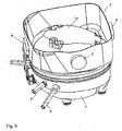
- a wall 2 made of metal, such as sheet steel, welded, which follows a circumferential line of the housing 1.
- This wall 2 forms the wall of the evaporator shell.
- the lying within the wall 2 sub-surface la of the housing forms the bottom of the evaporator shell.
- Fig. 2 is the same case as in Fig. 1 illustrated, but now with a possible embodiment of the invention: a fixed to the upper edge of the wall 2, the entire circumference of the edge covering circumferential damping element 5.
- the damping element 5 is made of an elastomer, for example made of rubber.
- Fig. 3 is a vertical section through the center of the housing 1 from Fig. 2 shown.
- the cross section of the circumferential damping element 5 becomes the section marked "B" at the upper right edge in Fig. 4 shown enlarged.
- Fig. 4 is the patch on the wall 2 circumferential damping element 5a shown in cross section. It has a circular cross-section and a radial groove which extends to about 0.7 diameter in the damping element 5.
- the groove corresponds in width to the thickness of the wall 2, so that a positive contact with the wall 2 is made possible.
- the sealing element 5a is placed on the upper edge of the wall 2.
- a circumferential damping element with rectangular cross-section 5b there are also other cross sections of the circumferential damping element 5 possible, for example, as in Fig. 5 represented, a circumferential damping element with rectangular cross-section 5b.
- the groove is arranged normal to the side surface of the rectangular cross-section, it also has a depth of about 70% of the cross-sectional height, its width is also adapted to the thickness of the wall 2, so that a positive contact between the damping element 5b and wall 2 is possible.
- Other cross sections of the damping element 5, such as triangular cross sections, are possible.
- the circumferential damping element 5, 5a, 5b is arranged on the free edge of the wall 2.
- a circumferential damping element is attached only to the inside or only on the outside of the wall 2, directly on the edge of the wall 2 subsequently or below, or embodiments where both on the inside and on the outside of the Wall 2 circumferential damping elements are arranged.
- the inner and outer damping element may be mounted at the same or different height.
- the circumferential damping element can be fixed under a bias, but it can also be fixed without bias. Is the damping element on the inside or on the Mounted outside the wall 2, the bias may be directed both inwardly and outwardly.
- the circumferential damping element on the inner and / or outer side may be formed approximately as a flat rubber band.
- Fig. 6 shows a perspective view of a non-inventive housing 1 with four lateral damping elements 6, which are mounted on the outside of the wall 2 substantially centrally in one of the four wall sections.
- the four wall sections result from the fact that the cross section of the wall 2 are not circular, but approximate the square shape.
- damping elements 6 all on the inside of the wall 2 or alternately on the inside and outside. Of course, more than four damping elements can be used.
- a single damping element 7 is mounted on the wall 2.
- the illustrated damping element 7 has the shape of a full cylinder having a groove in the radial direction to the middle of the cylinder. It would also be conceivable, however, to use a profile as in Fig. 3-5 is shown, wherein the attenuation is limited only to the region of the wall 2, on which the damping element is mounted.
- the shape of the groove is dimensioned so that the damping element 7 can be positively attached to the upper edge of the wall 2.
- the damping element 7 may be positively and / or positively and / or materially secured to the wall.
- Material for the damping element 7 are metal, plastic or composites in question.
- Fig. 8 the arrangement is off Fig. 7 added another, ie second damping element 8.
- the second illustrated damping element 8 has the shape of a full cylinder having a groove in the radial direction to the middle of the cylinder. Again, as below Fig. 7 explained, other forms conceivable.
- the shape of the groove is again dimensioned so that the damping element 8 can be positively attached to the upper edge of the wall 2.
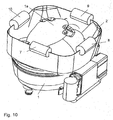
- damping elements 9, 10 can be added, as in Fig. 9 and Fig. 10 is shown.
- damping elements 7-10 can vary between the individual damping elements 7-10 and thus be better adapted to the requirements.
- the attachment of the damping elements can be done in different ways. (positive, positive and / or cohesive).
- Fig. 11 shows a diagram in which the radiated from a compressor housing sound power was measured. Shown is the third octave spectrum.
- the at least one damping element 5-10 by means of extrusion of a polymeric. Materials on the free upper edge of the wall 2, embracing this, applied. In principle, all adhesive materials are suitable for being applied directly in the area of the free upper edge of the wall 2.
- the free upper edge of the wall 2 is at least partially provided with adhesive whose mass forms one or more damping elements 5-10.
- the application of adhesive in the region of the free upper edge of the wall 2 can be carried out by means of any application method, e.g. by brushing, spraying, dipping etc.
Landscapes
- Engineering & Computer Science (AREA)
- Mechanical Engineering (AREA)
- General Engineering & Computer Science (AREA)
- Chemical & Material Sciences (AREA)
- Combustion & Propulsion (AREA)
- Physics & Mathematics (AREA)
- Thermal Sciences (AREA)
- Compressor (AREA)
- Applications Or Details Of Rotary Compressors (AREA)
Claims (15)
- Boîtier d'un compresseur de réfrigérant avec bac d'évaporation, dans lequel le bac d'évaporation est formé au moins par une paroi (2) métallique fixée directement et de façon étanche au boîtier (1) et suivant une ligne de périphérie du boîtier (1) et par au moins une partie de surface (la) du boîtier (1) située à l'intérieur de la paroi (2) et dans lequel au moins un élément amortisseur (5-10) est fixé sur la paroi (2) à distance du boîtier (1) pour amortir les vibrations transmises par le boîtier (1) à la paroi (2), caractérisé en ce que l'au moins un élément amortisseur (5-10) entoure le bord supérieur libre de la paroi (2).
- Boîtier avec bac d'évaporation selon la revendication 1, caractérisé en ce que l'au moins un élément amortisseur (5-10) est emboîté sur le bord supérieur libre de la paroi (2).
- Boîtier avec bac d'évaporation selon la revendication 1, caractérisé en ce que l'au moins un élément amortisseur (5-10) présente une rainure dont la largeur correspond sensiblement à l'épaisseur de la paroi (2) et l'élément amortisseur (5-10) est posé au moyen de cette rainure sur le bord supérieur de la paroi (2).
- Boîtier avec bac d'évaporation selon l'une des revendications 1 à 3, caractérisé en ce qu'un ou plusieurs éléments amortisseurs (6-10) se composent de métal.
- Boîtier avec bac d'évaporation selon la revendication 4, caractérisé en ce que l'élément amortisseur est formé d'un seul tenant avec la paroi (2).
- Boîtier avec bac d'évaporation selon l'une des revendications 1 à 5, caractérisé en ce qu'un ou plusieurs éléments amortisseurs (5, 5a, 5b) se composent de matière plastique (élastomère, plastomère ou duromère).
- Boîtier avec bac d'évaporation selon l'une des revendications 1 à 6, caractérisé en ce qu'un ou plusieurs éléments amortisseurs se composent de matériaux composites de structure multicouche, les différentes couches du matériau composite se composant en particulier d'élastomères et/ou de plastomères et/ou de duromères et/ou de métaux et/ou de bois.
- Boîtier avec bac d'évaporation selon la revendication 6 ou 7, caractérisé en ce qu'au moins un élément amortisseur (5, 5a, 5b) est fixé de manière à exercer une force de précontrainte sur la paroi (2).
- Boîtier avec bac d'évaporation selon l'une des revendications 1 à 8, caractérisé en ce qu'un ou plusieurs éléments amortisseurs (5-10) sont fixés à la paroi (2) par engagement positif et/ou friction et/ou par solidarité de matière.
- Boîtier avec bac d'évaporation selon l'une des revendications 1 à 9, caractérisé en ce qu'au moins un élément amortisseur (5-10) est fixé à la paroi de façon amovible.
- Boîtier avec bac d'évaporation selon l'une des revendications 1 à 10, caractérisé en ce qu'au moins un élément amortisseur (5-10) est fixé à la paroi de façon inamovible.
- Boîtier avec bac d'évaporation selon l'une des revendications 1 à 11, caractérisé en ce qu'au moins un élément amortisseur présente une fixation sensiblement linéaire.
- Boîtier avec bac d'évaporation selon l'une des revendications 1 à 12, caractérisé en ce qu'au moins un élément amortisseur (5-10) présente une fixation sensiblement plate.
- Boîtier avec bac d'évaporation selon l'une des revendications 1 à 13, caractérisé en ce qu'un élément amortisseur (5, 5a, 5b) est disposé le long de toute la périphérie de la paroi (2).
- Boîtier avec bac d'évaporation selon l'une des revendications 1 à 14, caractérisé en ce que la paroi (2) est soudée au boîtier (1).
Applications Claiming Priority (2)
| Application Number | Priority Date | Filing Date | Title |
|---|---|---|---|
| AT0060208U AT10950U1 (de) | 2008-10-21 | 2008-10-21 | Kältemittelverdichter |
| PCT/EP2009/063673 WO2010046343A1 (fr) | 2008-10-21 | 2009-10-19 | Compresseur frigorifique à bac de condensation |
Publications (2)
| Publication Number | Publication Date |
|---|---|
| EP2338014A1 EP2338014A1 (fr) | 2011-06-29 |
| EP2338014B1 true EP2338014B1 (fr) | 2017-03-22 |
Family
ID=41260048
Family Applications (1)
| Application Number | Title | Priority Date | Filing Date |
|---|---|---|---|
| EP09740307.5A Active EP2338014B1 (fr) | 2008-10-21 | 2009-10-19 | Carter d'un compresseur frigorifique avec bac d'evaporation |
Country Status (5)
| Country | Link |
|---|---|
| US (1) | US20110293446A1 (fr) |
| EP (1) | EP2338014B1 (fr) |
| CN (1) | CN102232170B (fr) |
| AT (1) | AT10950U1 (fr) |
| WO (1) | WO2010046343A1 (fr) |
Families Citing this family (8)
| Publication number | Priority date | Publication date | Assignee | Title |
|---|---|---|---|---|
| DE202013004850U1 (de) * | 2013-05-27 | 2013-06-05 | Thermo Electron Led Gmbh | Laborzentrifuge mit gedämmtem Kompressor |
| DE102015200394A1 (de) | 2015-01-14 | 2016-07-14 | BSH Hausgeräte GmbH | Kältegerät |
| CN104949421A (zh) * | 2015-06-30 | 2015-09-30 | 合肥美的电冰箱有限公司 | 冰箱 |
| KR102662655B1 (ko) | 2017-02-16 | 2024-05-03 | 삼성전자주식회사 | 압축기 |
| CN108326517B (zh) * | 2018-02-06 | 2019-11-05 | 杨益民 | 一种制冰机蒸发器的制造方法 |
| DE102018107304A1 (de) * | 2018-03-27 | 2019-10-02 | Man Energy Solutions Se | Turbolader |
| DE102018218019A1 (de) * | 2018-10-22 | 2020-04-23 | BSH Hausgeräte GmbH | Verdunstungsanordnung für ein Kältegerät |
| CN112944776B (zh) * | 2019-08-20 | 2022-10-28 | 三星电子株式会社 | 冰箱和家用电器 |
Citations (2)
| Publication number | Priority date | Publication date | Assignee | Title |
|---|---|---|---|---|
| US6112848A (en) * | 1998-09-23 | 2000-09-05 | Chrysler Corporation | Sound-dampened automobile interior components and methods for making same |
| JP2003287341A (ja) * | 2002-03-29 | 2003-10-10 | Fujitsu General Ltd | 冷蔵庫 |
Family Cites Families (8)
| Publication number | Priority date | Publication date | Assignee | Title |
|---|---|---|---|---|
| AT324370B (de) * | 1973-07-10 | 1975-08-25 | Bosch Hausgeraete Gmbh | Verdumstungsvorrichtung für schmelzwasser, insbesondere für periodisch abtaubare kühl- bzw. gefriergeräte |
| JPS62122289U (fr) * | 1986-01-27 | 1987-08-03 | ||
| JPS63122289U (fr) * | 1987-02-02 | 1988-08-09 | ||
| US5699677A (en) | 1996-11-07 | 1997-12-23 | White Consolidated Industries, Inc. | Compressor mounted drain pan utilizing polyurethane adhesive |
| KR100483556B1 (ko) * | 2002-09-17 | 2005-04-15 | 삼성광주전자 주식회사 | 밀폐형 압축기의 케이스 |
| AT7706U1 (de) * | 2004-05-11 | 2005-07-25 | Verdichter Oe Ges M B H | Verdichter mit integrierter verdunsterschale |
| AT8933U1 (de) * | 2005-12-20 | 2007-02-15 | Acc Austria Gmbh | Kältemittelkompressor |
| BRPI0700554A (pt) | 2007-01-30 | 2008-09-16 | Whirlpool Sa | arranjo de ressonadores para gabinete de aparelho de refrigeração |
-
2008
- 2008-10-21 AT AT0060208U patent/AT10950U1/de not_active IP Right Cessation
-
2009
- 2009-10-19 EP EP09740307.5A patent/EP2338014B1/fr active Active
- 2009-10-19 US US12/998,436 patent/US20110293446A1/en not_active Abandoned
- 2009-10-19 CN CN200980148078.5A patent/CN102232170B/zh active Active
- 2009-10-19 WO PCT/EP2009/063673 patent/WO2010046343A1/fr not_active Ceased
Patent Citations (2)
| Publication number | Priority date | Publication date | Assignee | Title |
|---|---|---|---|---|
| US6112848A (en) * | 1998-09-23 | 2000-09-05 | Chrysler Corporation | Sound-dampened automobile interior components and methods for making same |
| JP2003287341A (ja) * | 2002-03-29 | 2003-10-10 | Fujitsu General Ltd | 冷蔵庫 |
Also Published As
| Publication number | Publication date |
|---|---|
| EP2338014A1 (fr) | 2011-06-29 |
| CN102232170A (zh) | 2011-11-02 |
| AT10950U1 (de) | 2010-01-15 |
| WO2010046343A1 (fr) | 2010-04-29 |
| CN102232170B (zh) | 2015-09-23 |
| US20110293446A1 (en) | 2011-12-01 |
Similar Documents
| Publication | Publication Date | Title |
|---|---|---|
| EP2338014B1 (fr) | Carter d'un compresseur frigorifique avec bac d'evaporation | |
| DE3030711C2 (de) | Horizontaler Schwingkompressor | |
| DE60106114T2 (de) | Schwingungsdämpfende Vorrichtung für Fahrzeuge | |
| DE202006020806U1 (de) | Kurbelwelle einer Kolbenpumpe | |
| EP1697923A1 (fr) | Composant absorbant les bruits aeriens | |
| DE102016214289A1 (de) | Fahrzeug, mit einem Hochvoltspeicher | |
| DE69502027T2 (de) | Schwingungsdämpfende, hydraulische stütze | |
| EP0135845A2 (fr) | Moyens de montage d'un appareil pourvu de deux brides successives de support | |
| AT10802U1 (de) | Kältemittelverdichter | |
| EP3542062A1 (fr) | Compresseur de fluide de refroidissement | |
| DE102017106019A1 (de) | Schwingungstilger mit Auslenkungsbegrenzern für seine an zwei Enden elastisch gelagerte Tilgermasse | |
| DE102009030583A1 (de) | Kraftstofftank für ein Kraftfahrzeug | |
| DE4212190A1 (de) | Elastische lagerung mit einer fluidfuellung | |
| DE3700589C2 (de) | Schwingungsdämpfer | |
| WO2016008666A1 (fr) | Amortisseur de vibrations comprenant un capuchon de serrage | |
| DE4416449A1 (de) | Baueinheit aus einer Hydromaschine (Hydropumpe oder Hydromotor) und einem Träger | |
| WO2014060314A1 (fr) | Appareil frigorifique avec élément de montage | |
| DE102005038780A1 (de) | Linearverdichter, insbesondere Kältemittelverdichter | |
| DE3712656C2 (fr) | ||
| DE60004525T2 (de) | Saugschalldämpfer für einen hermetischen verdichter | |
| DE2933726A1 (de) | Schwingungsdaempfer | |
| DE102015206117A1 (de) | Schwingungsdämpfung eines Antriebs einer Wärmepumpe eines Haushaltsgeräts | |
| DE102005033509A1 (de) | Hydraulische Motorlagerbaueinheit | |
| DE102021110676A1 (de) | Schwingungstilger mit einstellbarer Tilgereigenfrequenz sowie Rotor und Windkraftanlage mit einem solchen Schwingungstilger | |
| DE102008030708B4 (de) | Mehrlagiger schalldämmender Hitzeschild |
Legal Events
| Date | Code | Title | Description |
|---|---|---|---|
| PUAI | Public reference made under article 153(3) epc to a published international application that has entered the european phase |
Free format text: ORIGINAL CODE: 0009012 |
|
| 17P | Request for examination filed |
Effective date: 20110523 |
|
| AK | Designated contracting states |
Kind code of ref document: A1 Designated state(s): AT BE BG CH CY CZ DE DK EE ES FI FR GB GR HR HU IE IS IT LI LT LU LV MC MK MT NL NO PL PT RO SE SI SK SM TR |
|
| AX | Request for extension of the european patent |
Extension state: AL BA RS |
|
| DAX | Request for extension of the european patent (deleted) | ||
| 17Q | First examination report despatched |
Effective date: 20131021 |
|
| RAP1 | Party data changed (applicant data changed or rights of an application transferred) |
Owner name: SECOP AUSTRIA GMBH |
|
| RAP1 | Party data changed (applicant data changed or rights of an application transferred) |
Owner name: SECOP AUSTRIA GMBH |
|
| RIC1 | Information provided on ipc code assigned before grant |
Ipc: F25D 21/14 20060101AFI20160204BHEP Ipc: F04B 39/12 20060101ALI20160204BHEP |
|
| GRAP | Despatch of communication of intention to grant a patent |
Free format text: ORIGINAL CODE: EPIDOSNIGR1 |
|
| INTG | Intention to grant announced |
Effective date: 20160421 |
|
| GRAJ | Information related to disapproval of communication of intention to grant by the applicant or resumption of examination proceedings by the epo deleted |
Free format text: ORIGINAL CODE: EPIDOSDIGR1 |
|
| INTC | Intention to grant announced (deleted) | ||
| GRAP | Despatch of communication of intention to grant a patent |
Free format text: ORIGINAL CODE: EPIDOSNIGR1 |
|
| INTG | Intention to grant announced |
Effective date: 20161014 |
|
| RAP1 | Party data changed (applicant data changed or rights of an application transferred) |
Owner name: SECOP GMBH |
|
| GRAS | Grant fee paid |
Free format text: ORIGINAL CODE: EPIDOSNIGR3 |
|
| GRAA | (expected) grant |
Free format text: ORIGINAL CODE: 0009210 |
|
| AK | Designated contracting states |
Kind code of ref document: B1 Designated state(s): AT BE BG CH CY CZ DE DK EE ES FI FR GB GR HR HU IE IS IT LI LT LU LV MC MK MT NL NO PL PT RO SE SI SK SM TR |
|
| REG | Reference to a national code |
Ref country code: GB Ref legal event code: FG4D Free format text: NOT ENGLISH |
|
| REG | Reference to a national code |
Ref country code: CH Ref legal event code: EP |
|
| REG | Reference to a national code |
Ref country code: AT Ref legal event code: REF Ref document number: 878195 Country of ref document: AT Kind code of ref document: T Effective date: 20170415 |
|
| REG | Reference to a national code |
Ref country code: IE Ref legal event code: FG4D Free format text: LANGUAGE OF EP DOCUMENT: GERMAN |
|
| REG | Reference to a national code |
Ref country code: DE Ref legal event code: R096 Ref document number: 502009013789 Country of ref document: DE |
|
| REG | Reference to a national code |
Ref country code: NL Ref legal event code: MP Effective date: 20170322 |
|
| PG25 | Lapsed in a contracting state [announced via postgrant information from national office to epo] |
Ref country code: NO Free format text: LAPSE BECAUSE OF FAILURE TO SUBMIT A TRANSLATION OF THE DESCRIPTION OR TO PAY THE FEE WITHIN THE PRESCRIBED TIME-LIMIT Effective date: 20170622 Ref country code: GR Free format text: LAPSE BECAUSE OF FAILURE TO SUBMIT A TRANSLATION OF THE DESCRIPTION OR TO PAY THE FEE WITHIN THE PRESCRIBED TIME-LIMIT Effective date: 20170623 Ref country code: FI Free format text: LAPSE BECAUSE OF FAILURE TO SUBMIT A TRANSLATION OF THE DESCRIPTION OR TO PAY THE FEE WITHIN THE PRESCRIBED TIME-LIMIT Effective date: 20170322 Ref country code: HR Free format text: LAPSE BECAUSE OF FAILURE TO SUBMIT A TRANSLATION OF THE DESCRIPTION OR TO PAY THE FEE WITHIN THE PRESCRIBED TIME-LIMIT Effective date: 20170322 Ref country code: LT Free format text: LAPSE BECAUSE OF FAILURE TO SUBMIT A TRANSLATION OF THE DESCRIPTION OR TO PAY THE FEE WITHIN THE PRESCRIBED TIME-LIMIT Effective date: 20170322 |
|
| REG | Reference to a national code |
Ref country code: LT Ref legal event code: MG4D |
|
| PG25 | Lapsed in a contracting state [announced via postgrant information from national office to epo] |
Ref country code: SE Free format text: LAPSE BECAUSE OF FAILURE TO SUBMIT A TRANSLATION OF THE DESCRIPTION OR TO PAY THE FEE WITHIN THE PRESCRIBED TIME-LIMIT Effective date: 20170322 Ref country code: LV Free format text: LAPSE BECAUSE OF FAILURE TO SUBMIT A TRANSLATION OF THE DESCRIPTION OR TO PAY THE FEE WITHIN THE PRESCRIBED TIME-LIMIT Effective date: 20170322 Ref country code: BG Free format text: LAPSE BECAUSE OF FAILURE TO SUBMIT A TRANSLATION OF THE DESCRIPTION OR TO PAY THE FEE WITHIN THE PRESCRIBED TIME-LIMIT Effective date: 20170622 |
|
| PG25 | Lapsed in a contracting state [announced via postgrant information from national office to epo] |
Ref country code: NL Free format text: LAPSE BECAUSE OF FAILURE TO SUBMIT A TRANSLATION OF THE DESCRIPTION OR TO PAY THE FEE WITHIN THE PRESCRIBED TIME-LIMIT Effective date: 20170322 |
|
| PG25 | Lapsed in a contracting state [announced via postgrant information from national office to epo] |
Ref country code: CZ Free format text: LAPSE BECAUSE OF FAILURE TO SUBMIT A TRANSLATION OF THE DESCRIPTION OR TO PAY THE FEE WITHIN THE PRESCRIBED TIME-LIMIT Effective date: 20170322 Ref country code: RO Free format text: LAPSE BECAUSE OF FAILURE TO SUBMIT A TRANSLATION OF THE DESCRIPTION OR TO PAY THE FEE WITHIN THE PRESCRIBED TIME-LIMIT Effective date: 20170322 Ref country code: EE Free format text: LAPSE BECAUSE OF FAILURE TO SUBMIT A TRANSLATION OF THE DESCRIPTION OR TO PAY THE FEE WITHIN THE PRESCRIBED TIME-LIMIT Effective date: 20170322 Ref country code: ES Free format text: LAPSE BECAUSE OF FAILURE TO SUBMIT A TRANSLATION OF THE DESCRIPTION OR TO PAY THE FEE WITHIN THE PRESCRIBED TIME-LIMIT Effective date: 20170322 |
|
| REG | Reference to a national code |
Ref country code: SK Ref legal event code: T3 Ref document number: E 24512 Country of ref document: SK |
|
| PG25 | Lapsed in a contracting state [announced via postgrant information from national office to epo] |
Ref country code: PL Free format text: LAPSE BECAUSE OF FAILURE TO SUBMIT A TRANSLATION OF THE DESCRIPTION OR TO PAY THE FEE WITHIN THE PRESCRIBED TIME-LIMIT Effective date: 20170322 Ref country code: PT Free format text: LAPSE BECAUSE OF FAILURE TO SUBMIT A TRANSLATION OF THE DESCRIPTION OR TO PAY THE FEE WITHIN THE PRESCRIBED TIME-LIMIT Effective date: 20170724 Ref country code: SM Free format text: LAPSE BECAUSE OF FAILURE TO SUBMIT A TRANSLATION OF THE DESCRIPTION OR TO PAY THE FEE WITHIN THE PRESCRIBED TIME-LIMIT Effective date: 20170322 Ref country code: IS Free format text: LAPSE BECAUSE OF FAILURE TO SUBMIT A TRANSLATION OF THE DESCRIPTION OR TO PAY THE FEE WITHIN THE PRESCRIBED TIME-LIMIT Effective date: 20170722 |
|
| REG | Reference to a national code |
Ref country code: DE Ref legal event code: R097 Ref document number: 502009013789 Country of ref document: DE |
|
| PLBE | No opposition filed within time limit |
Free format text: ORIGINAL CODE: 0009261 |
|
| STAA | Information on the status of an ep patent application or granted ep patent |
Free format text: STATUS: NO OPPOSITION FILED WITHIN TIME LIMIT |
|
| PG25 | Lapsed in a contracting state [announced via postgrant information from national office to epo] |
Ref country code: DK Free format text: LAPSE BECAUSE OF FAILURE TO SUBMIT A TRANSLATION OF THE DESCRIPTION OR TO PAY THE FEE WITHIN THE PRESCRIBED TIME-LIMIT Effective date: 20170322 |
|
| 26N | No opposition filed |
Effective date: 20180102 |
|
| PG25 | Lapsed in a contracting state [announced via postgrant information from national office to epo] |
Ref country code: SI Free format text: LAPSE BECAUSE OF FAILURE TO SUBMIT A TRANSLATION OF THE DESCRIPTION OR TO PAY THE FEE WITHIN THE PRESCRIBED TIME-LIMIT Effective date: 20170322 |
|
| PG25 | Lapsed in a contracting state [announced via postgrant information from national office to epo] |
Ref country code: MC Free format text: LAPSE BECAUSE OF FAILURE TO SUBMIT A TRANSLATION OF THE DESCRIPTION OR TO PAY THE FEE WITHIN THE PRESCRIBED TIME-LIMIT Effective date: 20170322 |
|
| REG | Reference to a national code |
Ref country code: CH Ref legal event code: PL |
|
| GBPC | Gb: european patent ceased through non-payment of renewal fee |
Effective date: 20171019 |
|
| REG | Reference to a national code |
Ref country code: IE Ref legal event code: MM4A |
|
| REG | Reference to a national code |
Ref country code: FR Ref legal event code: ST Effective date: 20180629 |
|
| PG25 | Lapsed in a contracting state [announced via postgrant information from national office to epo] |
Ref country code: LI Free format text: LAPSE BECAUSE OF NON-PAYMENT OF DUE FEES Effective date: 20171031 Ref country code: CH Free format text: LAPSE BECAUSE OF NON-PAYMENT OF DUE FEES Effective date: 20171031 Ref country code: GB Free format text: LAPSE BECAUSE OF NON-PAYMENT OF DUE FEES Effective date: 20171019 Ref country code: LU Free format text: LAPSE BECAUSE OF NON-PAYMENT OF DUE FEES Effective date: 20171019 |
|
| REG | Reference to a national code |
Ref country code: BE Ref legal event code: MM Effective date: 20171031 |
|
| PG25 | Lapsed in a contracting state [announced via postgrant information from national office to epo] |
Ref country code: BE Free format text: LAPSE BECAUSE OF NON-PAYMENT OF DUE FEES Effective date: 20171031 Ref country code: FR Free format text: LAPSE BECAUSE OF NON-PAYMENT OF DUE FEES Effective date: 20171031 |
|
| PG25 | Lapsed in a contracting state [announced via postgrant information from national office to epo] |
Ref country code: MT Free format text: LAPSE BECAUSE OF FAILURE TO SUBMIT A TRANSLATION OF THE DESCRIPTION OR TO PAY THE FEE WITHIN THE PRESCRIBED TIME-LIMIT Effective date: 20170322 |
|
| PG25 | Lapsed in a contracting state [announced via postgrant information from national office to epo] |
Ref country code: IE Free format text: LAPSE BECAUSE OF NON-PAYMENT OF DUE FEES Effective date: 20171019 |
|
| REG | Reference to a national code |
Ref country code: AT Ref legal event code: MM01 Ref document number: 878195 Country of ref document: AT Kind code of ref document: T Effective date: 20171019 |
|
| PG25 | Lapsed in a contracting state [announced via postgrant information from national office to epo] |
Ref country code: AT Free format text: LAPSE BECAUSE OF NON-PAYMENT OF DUE FEES Effective date: 20171019 |
|
| PG25 | Lapsed in a contracting state [announced via postgrant information from national office to epo] |
Ref country code: HU Free format text: LAPSE BECAUSE OF FAILURE TO SUBMIT A TRANSLATION OF THE DESCRIPTION OR TO PAY THE FEE WITHIN THE PRESCRIBED TIME-LIMIT; INVALID AB INITIO Effective date: 20091019 |
|
| PG25 | Lapsed in a contracting state [announced via postgrant information from national office to epo] |
Ref country code: CY Free format text: LAPSE BECAUSE OF NON-PAYMENT OF DUE FEES Effective date: 20170322 |
|
| PG25 | Lapsed in a contracting state [announced via postgrant information from national office to epo] |
Ref country code: MK Free format text: LAPSE BECAUSE OF FAILURE TO SUBMIT A TRANSLATION OF THE DESCRIPTION OR TO PAY THE FEE WITHIN THE PRESCRIBED TIME-LIMIT Effective date: 20170322 |
|
| PG25 | Lapsed in a contracting state [announced via postgrant information from national office to epo] |
Ref country code: TR Free format text: LAPSE BECAUSE OF FAILURE TO SUBMIT A TRANSLATION OF THE DESCRIPTION OR TO PAY THE FEE WITHIN THE PRESCRIBED TIME-LIMIT Effective date: 20170322 |
|
| P01 | Opt-out of the competence of the unified patent court (upc) registered |
Effective date: 20230517 |
|
| PGFP | Annual fee paid to national office [announced via postgrant information from national office to epo] |
Ref country code: IT Payment date: 20250929 Year of fee payment: 17 |
|
| PGFP | Annual fee paid to national office [announced via postgrant information from national office to epo] |
Ref country code: SK Payment date: 20250930 Year of fee payment: 17 |
|
| PGFP | Annual fee paid to national office [announced via postgrant information from national office to epo] |
Ref country code: DE Payment date: 20250929 Year of fee payment: 17 |