EP2338418B1 - Système de capture d'images radiographiques - Google Patents
Système de capture d'images radiographiques Download PDFInfo
- Publication number
- EP2338418B1 EP2338418B1 EP10196520A EP10196520A EP2338418B1 EP 2338418 B1 EP2338418 B1 EP 2338418B1 EP 10196520 A EP10196520 A EP 10196520A EP 10196520 A EP10196520 A EP 10196520A EP 2338418 B1 EP2338418 B1 EP 2338418B1
- Authority
- EP
- European Patent Office
- Prior art keywords
- radiation
- image capturing
- irradiation
- frame rate
- radiographic image
- Prior art date
- Legal status (The legal status is an assumption and is not a legal conclusion. Google has not performed a legal analysis and makes no representation as to the accuracy of the status listed.)
- Not-in-force
Links
- 230000005855 radiation Effects 0.000 claims description 275
- 238000003384 imaging method Methods 0.000 claims description 55
- 238000012545 processing Methods 0.000 claims description 38
- 230000001678 irradiating effect Effects 0.000 claims description 34
- 230000008859 change Effects 0.000 claims description 2
- 238000001514 detection method Methods 0.000 claims description 2
- 238000004891 communication Methods 0.000 description 37
- 230000001133 acceleration Effects 0.000 description 24
- 239000003990 capacitor Substances 0.000 description 13
- 238000006243 chemical reaction Methods 0.000 description 13
- 230000033001 locomotion Effects 0.000 description 13
- 238000000034 method Methods 0.000 description 13
- 230000000694 effects Effects 0.000 description 10
- 239000000463 material Substances 0.000 description 6
- 230000005540 biological transmission Effects 0.000 description 5
- 238000010586 diagram Methods 0.000 description 5
- 239000011159 matrix material Substances 0.000 description 5
- 239000011669 selenium Substances 0.000 description 5
- BUGBHKTXTAQXES-UHFFFAOYSA-N Selenium Chemical compound [Se] BUGBHKTXTAQXES-UHFFFAOYSA-N 0.000 description 4
- 206010047571 Visual impairment Diseases 0.000 description 4
- 238000003705 background correction Methods 0.000 description 4
- 238000012790 confirmation Methods 0.000 description 4
- 238000012937 correction Methods 0.000 description 4
- 229910052711 selenium Inorganic materials 0.000 description 4
- 239000000758 substrate Substances 0.000 description 4
- 230000008901 benefit Effects 0.000 description 3
- 239000004065 semiconductor Substances 0.000 description 3
- 230000001360 synchronised effect Effects 0.000 description 3
- MCVAAHQLXUXWLC-UHFFFAOYSA-N [O-2].[O-2].[S-2].[Gd+3].[Gd+3] Chemical compound [O-2].[O-2].[S-2].[Gd+3].[Gd+3] MCVAAHQLXUXWLC-UHFFFAOYSA-N 0.000 description 2
- 239000008280 blood Substances 0.000 description 2
- 210000004369 blood Anatomy 0.000 description 2
- XQPRBTXUXXVTKB-UHFFFAOYSA-M caesium iodide Chemical compound [I-].[Cs+] XQPRBTXUXXVTKB-UHFFFAOYSA-M 0.000 description 2
- 230000007246 mechanism Effects 0.000 description 2
- OAICVXFJPJFONN-UHFFFAOYSA-N Phosphorus Chemical compound [P] OAICVXFJPJFONN-UHFFFAOYSA-N 0.000 description 1
- 230000002421 anti-septic effect Effects 0.000 description 1
- 239000000356 contaminant Substances 0.000 description 1
- 230000001934 delay Effects 0.000 description 1
- 230000001419 dependent effect Effects 0.000 description 1
- 230000006866 deterioration Effects 0.000 description 1
- 238000003745 diagnosis Methods 0.000 description 1
- 239000010408 film Substances 0.000 description 1
- 230000006870 function Effects 0.000 description 1
- 238000002360 preparation method Methods 0.000 description 1
- 230000004044 response Effects 0.000 description 1
- 238000012216 screening Methods 0.000 description 1
- 230000003068 static effect Effects 0.000 description 1
- 239000010409 thin film Substances 0.000 description 1
- YDLQKLWVKKFPII-UHFFFAOYSA-N timiperone Chemical compound C1=CC(F)=CC=C1C(=O)CCCN1CCC(N2C(NC3=CC=CC=C32)=S)CC1 YDLQKLWVKKFPII-UHFFFAOYSA-N 0.000 description 1
- 229950000809 timiperone Drugs 0.000 description 1
Images










Classifications
-
- A—HUMAN NECESSITIES
- A61—MEDICAL OR VETERINARY SCIENCE; HYGIENE
- A61B—DIAGNOSIS; SURGERY; IDENTIFICATION
- A61B6/00—Apparatus or devices for radiation diagnosis; Apparatus or devices for radiation diagnosis combined with radiation therapy equipment
- A61B6/58—Testing, adjusting or calibrating thereof
- A61B6/586—Detection of faults or malfunction of the device
-
- A—HUMAN NECESSITIES
- A61—MEDICAL OR VETERINARY SCIENCE; HYGIENE
- A61B—DIAGNOSIS; SURGERY; IDENTIFICATION
- A61B6/00—Apparatus or devices for radiation diagnosis; Apparatus or devices for radiation diagnosis combined with radiation therapy equipment
- A61B6/44—Constructional features of apparatus for radiation diagnosis
- A61B6/4429—Constructional features of apparatus for radiation diagnosis related to the mounting of source units and detector units
- A61B6/4435—Constructional features of apparatus for radiation diagnosis related to the mounting of source units and detector units the source unit and the detector unit being coupled by a rigid structure
- A61B6/4441—Constructional features of apparatus for radiation diagnosis related to the mounting of source units and detector units the source unit and the detector unit being coupled by a rigid structure the rigid structure being a C-arm or U-arm
-
- A—HUMAN NECESSITIES
- A61—MEDICAL OR VETERINARY SCIENCE; HYGIENE
- A61B—DIAGNOSIS; SURGERY; IDENTIFICATION
- A61B6/00—Apparatus or devices for radiation diagnosis; Apparatus or devices for radiation diagnosis combined with radiation therapy equipment
- A61B6/54—Control of apparatus or devices for radiation diagnosis
- A61B6/542—Control of apparatus or devices for radiation diagnosis involving control of exposure
-
- A—HUMAN NECESSITIES
- A61—MEDICAL OR VETERINARY SCIENCE; HYGIENE
- A61B—DIAGNOSIS; SURGERY; IDENTIFICATION
- A61B6/00—Apparatus or devices for radiation diagnosis; Apparatus or devices for radiation diagnosis combined with radiation therapy equipment
- A61B6/54—Control of apparatus or devices for radiation diagnosis
- A61B6/548—Remote control of the apparatus or devices
-
- A—HUMAN NECESSITIES
- A61—MEDICAL OR VETERINARY SCIENCE; HYGIENE
- A61B—DIAGNOSIS; SURGERY; IDENTIFICATION
- A61B6/00—Apparatus or devices for radiation diagnosis; Apparatus or devices for radiation diagnosis combined with radiation therapy equipment
- A61B6/44—Constructional features of apparatus for radiation diagnosis
- A61B6/4423—Constructional features of apparatus for radiation diagnosis related to hygiene or sterilisation
Definitions
- the present invention relates to a radiographic image capturing system, and in particular, to a radiographic image capturing system that can carry out fluoroscopic imaging in which the capturing of radiographic images is carried out continuously.
- Radiographic image capturing devices that capture radiographic images expressed by irradiated radiation by using the radiation detector, are being put into practice.
- a radiographic image capturing device that uses the radiation detector has the advantages that images can be confirmed immediately, and fluoroscopic imaging (video image capturing), in which the capturing of radiographic images is carried out continuously, also can be carried out.
- image capturing methods for fluoroscopic imaging there are a method of capturing images at a predetermined frame rate while irradiating radiation continuously from a radiation source (continuous irradiation), and a method of, while irradiating radiation in the form of pulses synchronously with the frame rate (pulse irradiation), capturing images synchronously with the irradiation of the radiation.
- pulse irradiation the radiation can be irradiated for the time needed for imaging, and the amount of radiation that the patient is exposed to can be suppressed as compared with continuous irradiation, and there is therefore the advantage that the irradiated amount per unit time can be increased.
- pulse irradiation there is the need to synchronize the timing of irradiating the radiation from the radiation source and the timing of the image capturing at the radiation detector.
- JP-A Japanese Patent Application Laid-Open (JP-A) No. 2009-136481 discloses a technique in which a switch for switching between continuous irradiation and pulse irradiation is provided.
- imaging using C arm when the C arm is rotated and positioning of the imaged region is carried out, the form of irradiation is switched to pulse irradiation by the switch.
- the form of irradiation is switched to continuous irradiation by the switch, and image capturing is carried out.
- JP-A No. 2009-186439 discloses, in a wireless X-ray fluoroscopic system that is physically divided into an exposure unit and a sensor unit, a technique of generating beacon signals at a period that is associated with the frame rate of image capturing, and wirelessly synchronizing the irradiation timing and the image capturing timing.
- fluoroscopic images having smooth motion may not be captured by pulse irradiation in a case in which the frame rate is low.
- GB 2 357 953 A discloses a radiographic image capturing system in which fluoroscopic imaging can be performed at a suitable pulse rate ranging from high pulse rates suitable for smoothly reproducing motion, to low rates suitable for observing an essentially static image (page 53, second full paragraph).
- the present invention has been developed in consideration of the above, and provides a radiographic image capturing system that can capture fluoroscopic images having smooth motion even in cases in which the frame rate is low.
- a radiographic image capturing system comprises the features of claim 1. Preferred embodiments are defined by the dependent claims.
- fluoroscopic images having smooth motion can be captured even in cases in which the frame rate is low.
- control device may further have a selection section that selects whether the radiation irradiating device performs pulse irradiation or continuous irradiation, and in a case in which a frame rate of fluoroscopic imaging is less than or equal to a first frame rate threshold value, the controller may recommend continuous irradiation rather than pulse irradiation to the selection section, and, in a case in which the frame rate of fluoroscopic imaging is less than or equal to a second frame rate threshold value that is lower than the first frame rate threshold value, the controller may prohibit selection of pulse irradiation to the selection section. Due thereto, in a case in which the frame rate is low, fluoroscopic imaging is carried out by irradiating radiation continuously.
- the first frame rate threshold value may be from 15 fps to 60 fps
- the second frame rate threshold value may be from 5 fps to less than the first frame rate threshold value.
- the first frame rate threshold value may be 30 fps
- the second frame rate threshold value may be 15 fps.
- the controller may derive an irradiated amount of radiation per one image from an irradiation time of radiation per one image at a frame rate of fluoroscopic imaging and an irradiated amount of radiation per unit time from the radiation irradiating device, and, in a case in which the derived irradiated amount of radiation per one image is less than a minimum irradiated amount that is needed for capture of radiographic images, the controller may issue a warning or change a frame rate to the frame rate at which a minimum irradiated amount per one image is obtained.
- a warning can be given or image capturing can be carried out by changing to a frame rate at which the minimum irradiated amount is obtained.
- the controller may derive the irradiated amount of radiation per unit time from the radiation irradiating device by dividing a total amount of radiation permitted for an imaged region, that is an object of image capture, by a planned image capture time. Due thereto, even in a case in which image capturing for a planned image capture time is carried out, the total amount of radiation that is irradiated can be kept within the total amount of radiation that is permitted for the imaged region.
- the radiographic image capturing device may be further capable of performing still image capture, and in a case in which still image capture is to be performed, the controller may set a priority level of pulse irradiation so as to be higher than a priority level of continuous irradiation. Due thereto, in the case of still image capture, it is possible to urge image capturing to be carried out by the priority level of pulse irradiation.
- the radiation irradiating device may perform continuous irradiation with a smaller radiation amount per unit time than in a case in which the radiation irradiating device performs pulse irradiation. Due thereto, the amount of radiation to which the subject is exposed at the time of irradiating radiation continuously can be suppressed.
- the radiographic image capturing device may have: a radiation detector at which a plurality of pixels, that generate charges as a result of radiation being irradiated thereon and that accumulate the charge, are provided in a two-dimensional form, and that outputs the charge accumulated at the respective pixels as an electric signal; an amplifier that amplifies the electric signal output from the radiation detector; and an image capturing device controller that, in a case in which continuous irradiation is performed, carries out at least one of extending a charge accumulating time at the respective pixels so as to be longer than in pulse irradiation, increasing a gain amount of the amplifier so as to be greater than in pulse irradiation, and image processing that combines a plurality of adjacent pixels as one pixel. Due thereto, even in cases in which fluoroscopic imaging is carried out by continuous irradiation and the amount of radiation that is irradiated per unit time is reduced, good images can be obtained.
- the radiographic image capturing system may further have a detecting section that detects shaking of the radiation irradiating device, wherein, in a case in which a shaking amount of the radiation irradiating device detected by the detecting section during fluoroscopic imaging is greater than or equal to a first shaking threshold value, the controller may issue a warning, and, in a case in which the shaking amount is greater than or equal to a second shaking threshold value that is greater than the first shaking threshold value, the controller may stop irradiation of radiation from the radiation irradiating device.
- a warning can be given in a case in which the shaking amount is greater than the first shaking threshold value, and irradiation of the radiation can be stopped in a case in which the shaking amount is greater than the second shaking threshold value.
- the controller may issue the warning, and may stop irradiation of radiation, in a case in which the detecting section detects shaking of the radiation detection device during fluoroscopic imaging with continuous irradiation. Due thereto, in a case in which shaking of the radiation irradiating device is detected in the midst of fluoroscopic imaging while irradiating radiation continuously, a warning can be given or irradiation of the radiation can be stopped, in accordance with the amount of shaking.
- the fluoroscopic imaging is carried out by continuously irradiating radiation from the radiation irradiating device with respect to the radiographic image capturing device. Therefore, even in cases in which the frame rate is low, fluoroscopic images having smooth motion can be captured.
- a configuration of a radiology information system 10 (which will be called “the RIS 10" below) of the present embodiment will be described in reference to Fig. 1 .
- the RIS 10 is a system for managing information such as medical service appointments and diagnostic records in a radiology department and configures part of a hospital information system (HIS).
- HIS hospital information system
- the RIS 10 includes plural image capture request terminals 12 (which will be called “the terminals 12" below), RIS server 14 and radiographic image capturing systems 18 (hereinafter, referred to as "capturing systems") installed in individual radiographic image capturing rooms (or operating rooms) in a hospital being connected to a hospital network 16 that is structured by a wired or wireless local area network (LAN).
- the RIS 10 serves as part of the HIS that is disposed in the same hospital, and an HIS server (not shown) that manages the entire HIS is also connected to the hospital network 16.
- the terminals 12 are devices for doctors or radiologic technologists to input/browse diagnostic information and facility reservations, and requests to capture radiographic images or image capture reservations are also performed from the terminals 12.
- Each of the terminals 12 is configured by a personal computer equipped with a display device, and the terminals 12 are connected by the hospital network 16 to the RIS server 14 so as to be capable of communicating with each other.
- the RIS server 14 receives the image capture requests from the terminals 12, manages radiographic image capture schedules in the image capturing systems 18, and includes a database 14A.
- the database 14A stores information (data) relating to a patient, such as attribute information (name, sex, date of birth, age, blood type, weight, patient ID (identification) and the like) of the patient, medical history, consultation history, and radiographic images captured in the past.
- attribute information name, sex, date of birth, age, blood type, weight, patient ID (identification) and the like
- medical history consultation history
- radiographic images captured in the past.
- the image capturing systems 18 capture radiographic images by operation of the doctors or radiologic technologists in response to an instruction from the RIS server 14.
- Each of the capturing systems 18 is equipped with a radiation generator 34 that irradiates a subject with radiation X (see also Fig. 3 ) from a radiation source 130 (see also Fig. 2 ) of a radiation amount corresponding to image capture conditions, an electronic cassette 32 that includes a radiation detector 60 (see also Fig.
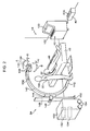
- Fig. 2 shows an example of the arrangements of the image capturing systems 18 in an radiographic image capturing room 44 and a configuration of the radiation generator 34 according to the present exemplary embodiment.
- the console 42 is mutually connected to the radiation generator 34 such that these devices transmit and receive various types of information by wired communication, but in Fig. 2 , the cables that interconnect these devices are omitted.
- the electronic cassette 32 and the console 42 may transmit and receive various types of information by wired or wireless communication.
- the radiation generator 34 relating to the present exemplary embodiment has a C arm 140.
- the radiation source 130 that emits radiation X is provided at one end of the C arm 140.
- An attachment structure 142, to and from which the electronic cassette 32 can be attached and removed, is provided at the other end of the C arm 140.
- Fig. 2 shows a state in which the electronic cassette 32 is removed from the attachment structure 142 and is provided between a bed 46, that is provided at the substantially central portion of the radiographic image capturing room 44, and a subject (patient) 48 who is lying on the bed 46.
- the radiation source 130 is provided at one end of the C arm 140 via a supporting shaft 136 and a pair of supporting plates 138.
- the radiation source 130 can be rotated in direction A and direction B in Fig. 2 around the supporting shaft 136, and can be rotated together with the supporting plates 138 in direction C and direction D in Fig. 2 around a tangent line of the arc of the C arm 140.
- a C arm holding portion 144 that holds the C arm 140 such that the C arm 140 can rotate clockwise and counterclockwise in Fig. 2 , is provided at a position that abuts the outer periphery of the cylindrical surface of the C arm 140.
- the C arm holding portion 144 is held, via a C arm holding portion 146, at a support 148 so as to freely move vertically. Further, the C arm holding portion 144 is supported so as to be able to rotate around a horizontal axis with respect to the C arm holding portion 146.
- the radiation generator 34 has a main body 150 that incorporates therein a communication interface 132, a radiation source controller 134, and the like that are described below.
- the lower end of the support 148 is mounted to a support supporting section 152 that projects-out to the side from a vicinity of the lower end portion of the housing of the main body 150.
- Wheels 154 are provided at the bottom portion of the main body 150, such that the radiation generator 34 can move within the hospital.
- the cradle 40 and the console 42 are set in a vicinity of a wall surface in the radiographic image capturing room 44 relating to the present exemplary embodiment.
- a housing portion 40A that can house the electronic cassette 32 is formed in the cradle 40.
- the electronic cassette 32 When the electronic cassette 32 stands by, the electronic cassette 32 is housed in the housing portion 40A of the cradle 40 and the built-in battery is charged, and when a radiographic image is to be captured, the electronic cassette 32 is removed from the cradle 40 and disposed in the area of the patient 30 of which an image is to be captured, or mounted on the attachment structure 142 of the C arm 140 of the radiation generator 34.
- the electronic cassette 32 is not limited to being used in the operating room 44 and can also be applied to medical screenings and rounds inside a hospital, for example.
- Fig. 3 shows the internal configuration of the electronic cassette 32 pertaining to the exemplary embodiment.
- the electronic cassette 32 is equipped with a casing 54 formed by a material that allows the radiation X to be transmitted therethrough, and the electronic cassette 32 is configured to have a waterproof and hermetic structure. There is the fear that blood or other contaminant may adhere to the electronic cassette 32 when the electronic cassette 32 is used in an operating room or the like.
- the electronic cassette 32 is configured to have a waterproof and hermetic structure and is washed with an antiseptic as needed, so that the one electronic cassette 32 can be used repeatedly.
- a grid 58 that removes scattered radiation of the radiation X resulting from the patient
- the radiation detector 60 that detects the radiation X that has been transmitted through the patient
- a lead plate 62 that absorbs back scattered radiation of the radiation X.
- the irradiated surface 56 of the casing 54 may also be configured by the grid 58.
- a connection terminal 32A for connecting a cable 43 is provided at a side of the casing 54.
- a case 31 that houses electronic circuits including a microcomputer and a rechargeable secondary battery is disposed on one end side of the inside of the casing 54.
- the radiation detector 60 and associated electronic circuits are actuated by power supplied from the secondary battery disposed in the case 31.
- a lead plate or the like may be disposed on the irradiated surface 56 side of the case 31 in order to avoid a situation where the various circuits housed inside the case 31 sustain damage in accompaniment with being irradiated with the radiation X.
- the electronic cassette 32 is configured as a rectangular parallelepiped in which the irradiated surface 56 is formed in a rectangle shape, and the case 31 is disposed at one side in a longitudinal direction of the rectangular parallelepiped.
- Fig. 4 shows a block diagram showing the detailed configuration of the radiographic image capturing system 18.
- a connection terminal 34A for performing communication with the console 42 is disposed in the radiation generator 34.
- a connection terminal 42A for performing communication with the radiation generator 34, a connection terminal 42B for performing communication with the electronic cassette 32 are disposed in the console 42.
- the connection terminal 34A of the radiation generator 34 and the connection terminal 42A of the console 42 are connected with a cable 35.
- the cable 43 is connected to the connection terminal 32A and the electronic cassette 32 is connected to the console 42 via the cable 43.
- the radiation detector 60 built into the electronic cassette 32 is configured by a photoelectric conversion layer that absorbs and converts the radiation X into electric charges being layered on a TFT active matrix substrate 66.
- the photoelectric conversion layer contains, for example, amorphous selenium (a-Se) whose main component (e.g., having a content percentage equal to or greater than 50%) is selenium, and when the photoelectric conversion layer is irradiated with the radiation X, the photoelectric conversion layer converts the radiation X which has been irradiated into electric charges by generating, inside itself, electric charges (electron-hole pairs) of an electric charge amount corresponding to the amount of the radiation X which has been irradiated.
- a-Se amorphous selenium
- the radiation detector 60 may also, instead of a material that directly converts the radiation X into electric charges such as amorphous selenium, use a fluorescent material and a photoelectric conversion element (photodiode) to indirectly convert the radiation X into electric charges.
- a fluorescent material As the phosphor material, gadolinium oxysulfide (GOS) and cesium iodide (CsI) are known. In this case, conversion of the radiation X into light is performed by the fluorescent material, and conversion of the light into electric charges is performed by the photodiode of the photoelectric conversion element.
- GOS gadolinium oxysulfide
- CsI cesium iodide
- the photoelectric conversion layer corresponding to the individual pixels 74 is schematically shown as photoelectric converters 72) equipped with storage capacitors 68 that store the electric charges that have been generated by the photoelectric conversion layer and TFTs 70 for reading the electric charges that have been stored in the storage capacitors 68 are arranged in a matrix.
- the electric charges that have been generated in the photoelectric conversion layer by the irradiation of the electronic cassette 32 with the radiation X are stored in the storage capacitors 68 of the individual pixels 74.
- the image information that had been carried in the radiation X with which the electronic cassette 32 was irradiated is converted into electric charge information (an amount of electric charge) and is held in the radiation detector 60.
- the TFT active matrix substrate 66 there are disposed plural gate lines 76, which extend in one direction (row direction) and are for switching ON and OFF the TFTs 70 of the individual pixels 74, and plural data lines 78, which extend in a direction (column direction) orthogonal to the gate lines 76 and are for reading the stored electric charges from the storage capacitors 68 via the TFTs 70 that have been switched ON.
- the individual gate lines 76 are connected to a gate line driver 80, and the individual data lines 78 are connected to a signal processor 82.
- the TFTs 70 of the individual pixels 74 are switched ON in order in row units by signals that are supplied via the gate lines 76 from the gate line driver 80.
- the electric charges that are stored in the storage capacitors 68 of the pixels 74 whose TFTs 70 have been switched ON are transmitted through the data lines 78 as electric charge signals and are inputted to the signal processor 82. Consequently, the electric charges that are stored in the storage capacitors 68 of the individual pixels 74 are read in order in row units.
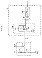
- Fig. 5 shows an equivalent circuit diagram focusing on one pixel portion of the radiation detector 60 pertaining to the exemplary embodiment.
- a source of the TFT 70 is connected to the data line 78, and the data line 78 is connected to the signal processor 82. Further, a drain of the TFT 70 is connected to the storage capacitor 68 and to the photoelectric converter 72, and a gate of the TFT 70 is connected to the gate line 76.
- the signal processor 82 is equipped with a sample/hold circuit 84 for each of the individual data lines 78.
- the electric charge signals that have been transmitted through the individual data lines 78 are held in the sample/hold circuits 84.
- the sample/hold circuit 84 includes an operational amplifier (op-amp) 84A and a capacitor 84B and converts the electric charge signal into an analog voltage.
- a switch 84C which serves as a reset circuit that causes both electrodes of the capacitor 84B to short to cause the electric charge stored in the capacitor 84B to be discharged as a result of the switch 84C being switched ON, is disposed in the sample/hold circuit 84.
- the gain amount of the operational amplifier 84A can be adjusted by control of a cassette controller 92 which will be described later.
- a multiplexer 86 and an analog/digital (A/D) converter 88 are connected in this order at an output side of the sample/hold circuits 84.
- the electric charge signals held in the individual sample/hold circuits 84 are converted into analog voltages, and the analog voltages are inputted in order (serially) to the multiplexer 86 and converted into digital image data by the A/D converter 88.
- An image memory 90 is connected to the signal processor 82 (see Fig. 4 ).
- the image data that have been outputted from the A/D converter 88 of the signal processor 82 are stored in order in the image memory 90.
- the image memory 90 has a storage capacity that is capable of storing plural frames' worth of image data representing a radiographic image, and each time capturing of a radiographic image is performed, image data obtained by the capturing is sequentially stored in the image memory 90.
- the image memory 90 is connected to the cassette controller 92 that controls operation of the entire electronic cassette 32.
- the cassette controller 92 is realized by a microcomputer, and includes a central processing unit (CPU) 92A, a memory 92B including a read only memory (ROM) and a random access memory (RAM), and an non-volatile storage section 92C that may formed of a hard disk drive (HDD), flash memory or the like.
- a radio communication unit 94 and a wired communication unit 95 are connected to the cassette controller 92.
- the radio communication unit 94 is adapted to a wireless local area network (LAN) specification represented by for example IEEE (Institute of Electrical and Electronics Engineers) 802.11a/b/g and controls the transmission of various types of information between the electronic cassette 32 and an external device by radio communication.
- the wired communication unit 95 is connected to the connection terminal 32A and controls the transmission of various types of various types of information between the electronic cassette 32 and the console 42 via the connection terminal 32A and the cable 43.
- the cassette controller 92 can perform communication with the console 42 via the radio communication unit 94 or the wired communication unit 95, and transmits various types of information to and receives various types of information from the console 42 via the radio communication unit 94 or the wired communication unit 95.
- the cassette controller 92 stores exposure conditions received via the radio communication unit 94 or the wired communication unit 95, which will be described later, and starts reading out of charges based on the exposure conditions.
- a power source 96 is provided in the electronic cassette 32, and the various circuits and elements mentioned above (such as the gate line driver 80, the signal processor 82, the image memory 90, the radio communication unit 94, the wired communication unit 95, and the microcomputer that functions as the cassette controller 92) are actuated by power supplied from the power source 96.
- the power source 96 has a built-in battery (a rechargeable secondary battery) so as to not impair the portability of the electronic cassette 32, and the power source 96 supplies power to the various circuits and elements from the charged battery. In Fig. 4 , wirings connecting the various circuits and elements and the power source 96 are omitted.
- the console 42 is configured as a server computer and is equipped with a display 100, which displays operation menus and radiographic images that have been captured, and an operation panel 102, which includes plural keys and by which various types of information and operation instructions are inputted.
- the console 42 pertaining to the exemplary embodiment is equipped with a central processing unit (CPU) 104 that controls operation of the entire device, a read-only memory (ROM) 106 in which various programs including a control program are stored beforehand, a random-access memory (RAM) 108 that temporarily stores various types of data, a hard disk drive (HDD) 110 that stores and maintains various types of data, a display driver 112 that controls the display of various types of information on the display 100, and an operation input detector 114 that detects states of operation with respect to the operation panel 102.
- CPU central processing unit
- ROM read-only memory
- RAM random-access memory
- HDD hard disk drive
- display driver 112 controls the display of various types of information on the display 100
- an operation input detector 114 that detects states of operation with respect to the operation panel 102.
- the console 42 further includes a communication interface 116 that is connected to the connection terminal 42A and transmits various types of information to and receives various types of information from the radiation generator 34 via the connection terminal 42A and the cable 35 such as the exposure conditions which will be described later, a radio communication unit 118 that transmits various types of information to and receives various types of information from the radiation generator 34 such as the exposure conditions, and a wired communication unit 120 that is connected to the connection terminal 42B and transmits various types of information to and receives various types of information from the electronic cassette 32 such as image data via the connection terminal 42B and the cable 43.
- a communication interface 116 that is connected to the connection terminal 42A and transmits various types of information to and receives various types of information from the radiation generator 34 via the connection terminal 42A and the cable 35 such as the exposure conditions which will be described later
- a radio communication unit 118 that transmits various types of information to and receives various types of information from the radiation generator 34 such as the exposure conditions
- a wired communication unit 120 that is connected to the connection terminal 42
- the CPU 104, the ROM 106, the RAM 108, the HDD 110, the display driver 112, the operation input detector 114, the communication interface 116, the radio communication unit 118, and the wired communication unit 120 are interconnected via a system bus BUS.
- the CPU 104 can access the ROM 106, the RAM 108 and the HDD 110, can control the display of various types of information on the display 100 via the display driver 112, can control the transmission of various types of information to and the reception of various types of information from the radiation generator 34 via the communication interface 116, can control the transmission of various types of information to and the reception of various types of information from the electronic cassette 32 via the radio communication unit 118, and can control the transmission of various types of information to and the reception of various types of information from the electronic cassette 32 via the wired communication unit 120. Further, the CPU 104 can grasp states of operation by a user with respect to the operation panel 102 via the operation input detector 114.
- the radiation generator 34 is equipped with the radiation source 130 that outputs the radiation X, a communication interface 132 that transmits various types of information to and receives various types of information from the console 42 such as exposure conditions, and a radiation source controller 134 that controls the radiation source 130 on the basis of received exposure conditions.
- the radiation source controller 134 is also realized by a microcomputer, stores the received exposure conditions, and causes the radiation source 130 to irradiate the radiation X on the basis of the stored exposure conditions.
- An acceleration sensor 156 is provided at the radiation generator 34 relating to the present exemplary embodiment in a vicinity of the position where the radiation source 130 is set at the C arm 140 as shown in Fig. 2 , in order to prevent failures in the capturing of radiographic images caused by some object contacting or colliding with the radiation source 130.
- the acceleration sensor 156 is a sensor that senses the way of application of velocity with respect to three axial directions that are the vertical direction, the left-right direction and the front-back direction.
- the acceleration sensor 156 may be any type provided that it can detect acceleration, and may be, for example, a piezoresistance type sensor or an electrostatic capacity type sensor.
- the acceleration sensor 156 is connected to the radiation source controller 134. Signals, that are outputted from the acceleration sensor 156 and express the accelerations in the three axial directions, are inputted to the radiation source controller 134.
- the radiation source controller 134 transmits the acceleration information, that is inputted from the acceleration sensor 156 and expresses the accelerations in the three axial directions, to the console 42 via the communication interface 132.
- the electronic cassette 32 and the console 42 pertaining to the exemplary embodiment perform wired communication when they are interconnected by the communication cable 43 and perform radio communication when they are not interconnected by the communication cable 43.
- the capturing system 18 of the present exemplary embodiment is configured to be capable of selecting a capturing mode from still image capturing that performs capturing one by one, or fluoroscopic imaging that performs capturing continuously. Further, the capturing system 18 is configured to be capable of selecting continuous irradiation in which radiation is continuously irradiated from the radiation source 130 during the capturing or pulse irradiation in which radiation is irradiated in pulsed form from the radiation source 130 in synchronization with the frame rate of the capturing during the capturing.
- One of the terminals 12 receives an image capture request from a doctor or a radiologic technologist.
- the image capture request there are designated a patient to be captured, the area of the patient to be captured, the capturing more, and optionally the tube voltage, the tube current, the irradiation time, and the total radiation amount.
- the terminal 12 notifies the RIS server 14 of the content of the received image capture request.
- the RIS server 14 stores, in the database 14A, the content of the image capture request which has been notified by the terminals 12.
- the console 42 accesses the RIS 14 to acquire the content of the image capture request and the attribute information (data) of a patient to be captured from the RIS server 14 and display the content of the image capture request and the attribute data of the patient on the display 100 (see Fig. 4 ).
- An operator initiates capture of a radiographic image on the basis of the content of the image capture request displayed on the display 100.
- the operator disposes the electronic cassette 32 between the bed 46 and the affected area of the subject 48 in accordance with the area of image capture, without connecting the cable 43 to the electronic cassette 32 and the console 42 in case of using radio communication, or after connecting the electronic cassette 32 and the console 42 with the cable 43.
- the operator designates still image capturing or fluoroscopic imaging as the image capturing mode.
- still image capturing is designated as the image capturing mode
- the operator designates, at the operation panel 102, the exposure conditions such as the tube voltage, tube current, irradiation time, and the like for the time when the radiation X is irradiated.
- fluoroscopic imaging is designated as the image capturing mode
- the operator designates, at the operation panel 102, the exposure conditions such as the frame rate, the tube voltage, the tube current, and the like.
- the operator designates by which of continuous irradiation or pulse irradiation the image capturing is to be carried out.
- pulse irradiation in pulse irradiation, radiation can be irradiated for the time period needed for image capturing, and the amount of radiation that the patient is exposed to can be suppressed as compared with continuous irradiation. Therefore, pulse irradiation has the advantage that the irradiated amount per unit time is increased.
- the ranges over which the tube voltage and the tube current can be designated from the operation panel 102 are limited so that the irradiated radiation amount per unit time is reduced as compared with a case in which pulse irradiation of radiation is carried out.
- the amount of radiation to which the subject is exposed at the time of continuous irradiation can thereby be suppressed.
- the respective images may become frame-advanced images having stopped motion.
- the image capturing interval is large and after-images of the eyes also disappear, and therefore, fluoroscopic images having smooth motion cannot be captured.
- frame rate threshold values are stored in advance in the HDD 110, and the irradiation mode to be prioritized is judged by comparing the frame rate of the fluoroscopic imaging with the threshold values.
- the time resolution of a human eye is around 50 ms to 100 ms, and flashing of light that is shorter than this time is perceived as continuous lighting.
- two frame rate threshold values (a first frame rate threshold value and a second frame rate threshold value) are stored.
- the first frame rate threshold value may be a frame rate at which a large majority of people do not sense flickering.
- the first frame rate threshold value may be from 15fps (frames per second) to 60fps, and more preferably, from 15fps to 30fps.
- the second frame rate threshold value may be a frame rate at which a large majority of people sense flickering.
- the second frame rate threshold value may be from 5fps to less that the first frame rate threshold value, and more preferably, from 5fps to less than 15fps.
- the first frame rate threshold value is set to 30fps and the second frame rate threshold value is set to 15fps.
- the first frame rate threshold value may be 24fps and the second frame rate threshold value may be 5fps.
- Fig. 7 is a flowchart showing the flow of processings of a priority irradiation mode judging processing program that is executed at the CPU 104 relating to the present exemplary embodiment.
- This program is stored in advance in a predetermined area of the HDD 110, and is executed when a designating operation, that designates the image capturing mode and the exposure conditions, is carried out with respect to the operation panel 102.
- step 200 of Fig. 7 judgment is made as to whether or not the designated image capturing mode is still image capturing. If the judgment is affirmative, the routine moves on to step 202. If the judgment is negative, the routine proceeds to step 204.
- step 202 the priority level of continuous irradiation is set low, the priority level of pulse irradiation is set high, and the present priority irradiation mode judging processing program ends.
- step 204 judgment is made as to whether or not the frame rate of the fluoroscopic imaging is greater than or equal to the first frame rate threshold value (e.g., 30 fps). If the judgment is affirmative, the routine moves on to step 206, whereas if the judgment is negative, the routine moves on to step 208.
- the first frame rate threshold value e.g. 30 fps
- step 206 the priority levels of continuous irradiation and pulse irradiation are set low, and the present priority irradiation mode judging processing program ends.
- step 208 judgment is made as to whether or not the frame rate of the fluoroscopic imaging is less than or equal to the second frame rate threshold value (e.g., 15 fps). If the judgment is affirmative, the routine moves on to step 210, whereas if the judgment is negative, the routine proceeds to step 212.
- the second frame rate threshold value e.g. 15 fps
- step 210 pulse irradiation is prohibited, the priority level of continuous irradiation is set high, and the present priority irradiation mode judging processing program ends.
- step 212 the priority level of pulse irradiation is set low, the priority level of continuous irradiation is set high, and present priority irradiation mode judging processing program ends.
- the priority level of continuous irradiation is low, and the priority level of pulse irradiation is high.
- the priority levels of continuous irradiation and pulse irradiation are determined in accordance with the frame rate of the fluoroscopic imaging.
- the designation screen is displayed when receiving designation (selection) of which of continuous irradiation and pulse irradiation the radiographic image capturing is to be carried out.
- the selection screen displays that the type of irradiation whose priority level is high is recommended, and that the type of irradiation that is prohibited cannot be selected in the selection screen.
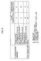
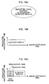
- Fig. 9A illustrates an example of a selection screen 190 that is displayed on the display 100 in a case in which the priority level of pulse irradiation is low and the priority level of continuous irradiation is high.
- FIG. 9B illustrates an example of the selection screen 190 that is displayed on the display 100 in a case in which pulse irradiation is prohibited and the priority level of continuous irradiation is high.
- a button 190A that designates continuous irradiation and a button 190B that designates pulse irradiation are provided in the designation screen 190.
- a message that this type of irradiation is recommended is displayed next to the button 190A.
- pulse irradiation that is prohibited is made invalid so as to not be able to be selected.
- the fluoroscopic imaging is carried out by irradiating radiation continuously. Therefore, fluoroscopic images having smooth motion can be captured.
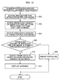
- Fig. 10 is a flowchart showing the flow of processings of a minimum irradiated amount ensuring judgment processing program that is executed by the CPU 104 relating to the present exemplary embodiment. Note that this program is stored in advance in a predetermined area of the HDD 110, and is executed when a designating operation that designates fluoroscopic imaging by continuous irradiation is carried out with respect to the operation panel 102.
- the irradiation time of the radiation per one image is derived from the frames of the fluoroscopic imaging.
- the image read-out time that is required for reading-out one image is stored in advance in the HDD 110, and the planned image capturing time per one image is determined from the frame rate. By subtracting the image read-out time from this planned image capturing time, the irradiation time of the radiation per one image is derived.
- step 302 the irradiated amount of radiation per unit time is derived from the designated tube voltage and tube current.
- step 304 the irradiated amount of radiation per one image is derived by multiplying the irradiation time of radiation per one image, that was derived in step 300, by the irradiated amount of radiation per unit time that was derived in step 304.
- step 306 judgment is made as to whether or not the irradiated amount of radiation per one image is greater than or equal to a minimum irradiated amount. If the judgment is affirmative, the routine moves on to step 308, and, after image capturing is permitted, the present minimum irradiated amount ensuring judgment processing program ends. If the judgment is negative, the routine moves on to step 310.
- step 310 by dividing the minimum irradiated amount by the irradiated amount of radiation per unit time, the irradiation time of radiation at which the minimum irradiated amount is obtained is determined, and the frame rate at which this irradiation time is obtained is derived.
- step 312 the fact that the minimum irradiated amount needed for radiographic image capturing cannot be ensured is displayed on the display 100, and the frame rate derived in above step 310 is displayed on the display 100 as a frame rate at which the minimum irradiated amount can be ensured, and the present minimum irradiated amount ensuring judgment processing program ends.
- warning can be given in a case in which the minimum irradiated amount that is needed for capturing radiographic images cannot be ensured.
- the warning processing is carried out to display, on the display 100 of the console 42, a display of the fact that the minimum irradiated amount that is needed cannot be ensured.
- the present exemplary embodiment is not limited to the same.
- any other processing that can urge caution such as providing a buzzer at the console 42 and carrying out the processing of sounding the buzzer, or providing a speaker at the console 42 and carrying out the processing of issuing a voice message that urges caution from the speaker, or providing a warning lamp at the console 42 and carrying out the processing of lighting the warning lamp or causing the warning lamp to flash, or the like, or combinations thereof, may be utilized.
- the operator may again carry out frame rate designation.
- image capturing is permitted and the display 100 displays that preparations for image capturing have been completed, the operator may carry out an image capturing instructing operation that instructs image capturing with respect to the operation panel 102 of the console 42.
- the console 42 starts the image capturing operations shown in Fig. 11 through Fig. 14 that are described below, in accordance with which of still image capturing by continuous irradiation, still image capturing by pulse irradiation, fluoroscopic imaging by continuous irradiation, and fluoroscopic imaging by pulse irradiation has been designated.
- Fig. 11 is a time chart showing the flow of image capturing operations in a case in which still image capturing by continuous irradiation is designated.
- the console 42 transmits instruction information (data), that instructs the start of exposure, to the radiation generator 34 and the electronic cassette 32.
- the radiation generator 34 When the radiation generator 34 receives the instruction data that instructs the start of exposure, the radiation generator 34 starts generating and emitting radiation at the tube voltage and tube current corresponding to the exposure conditions received from the console 42.
- the cassette controller 92 of the electronic cassette 32 controls the gate line driver 80 and causes on signals to be outputted from the gate line driver 80 to the respective gate lines 76 in order and line-by-line, and turns the respective TFTs 70, that are connected to the respective gate lines 76, on in order and line-by-line.
- the respective TFTs 70 that are connected to the respective gate lines 76 are turned on in order and line-by-line, the charges, that have been accumulated in the respective storage capacitors 68, flow-out in order and line-by-line to the respective data lines 78 as electric signals.
- the electric signals that have flowed-out to the respective data lines 78 are converted into digital image data at the signal processor 82, are stored in the image memory 90, and are transmitted to the console 42.
- the console 42 When the console 42 receives the image data, the console 42 transmits instruction data, that instructs the end of exposure, to the radiation generator 34, and carries out image processings that effect various types of corrections, such as shading correction and the like, on the received image data, and stores the image data after the image processing in the HDD 110.
- instruction data that instructs the end of exposure
- the radiation generator 34 When the console 42 receives the image data, the console 42 transmits instruction data, that instructs the end of exposure, to the radiation generator 34, and carries out image processings that effect various types of corrections, such as shading correction and the like, on the received image data, and stores the image data after the image processing in the HDD 110.
- the radiation generator 34 When the radiation generator 34 receives the instruction data that instructs the end of exposure, the radiation generator 34 ends the generating and emitting of radiation.
- the image data stored in the HDD 110 is displayed on the display 100 for confirmation of the captured radiographic image and the like, and is transferred to the RIS server 14 and stored in the database 14A as well. Due thereto, a doctor can carry out interpretation of the captured radiographic image, diagnosis, and the like.
- Fig. 12 is a time chart showing the flow of image capturing operations in a case in which still image capturing by pulse irradiation is designated.
- the console 42 transmits instruction data, that instructs the start of exposure, to the radiation generator 34 and the electronic cassette 32.
- the radiation generator 34 When the radiation generator 34 receives the instruction data that instructs the start of exposure, the radiation generator 34 generates and emits radiation at the tube voltage and tube current and for the irradiation time that correspond to the exposure conditions received from the console 42.
- the cassette controller 92 of the electronic cassette 32 controls the gate line driver 80 and causes on signals to be outputted from the gate line driver 80 to the respective gate lines 76 in order and line-by-line, and turns the respective TFTs 70, that are connected to the respective gate lines 76, on in order and line-by-line.
- the respective TFTs 70 that are connected to the respective gate lines 76 are turned on in order and line-by-line, the charges, that have been accumulated in the respective storage capacitors 68, flow-out in order and line-by-line to the respective data lines 78 as electric signals.
- the electric signals that have flowed-out to the respective data lines 78 are converted into digital image data at the signal processor 82, are stored in the image memory 90, and are transmitted to the console 42.
- the image data transmitted to the console 42 is subjected at the console 42 to image processings that effect various types of corrections, such as shading correction and the like, and is stored in the HDD 110.
- the image data stored in the HDD 110 is displayed on the display 100 for confirmation of the captured radiographic image and the like, and is transferred to the RIS server 14 and stored in the database 14A as well.
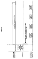
- Fig. 13 is a time chart showing the flow of image capturing operations in a case in which fluoroscopic imaging by continuous irradiation is designated.
- the console 42 transmits instruction data, that instructs the start of exposure, to the radiation generator 34 and the electronic cassette 32.
- the radiation generator 34 When the radiation generator 34 receives the instruction data that instructs the start of exposure, the radiation generator 34 starts irradiating radiation at the tube voltage and tube current corresponding to the exposure conditions received from the console 42.
- the cassette controller 92 of the electronic cassette 32 When the cassette controller 92 of the electronic cassette 32 receives the instruction data that instructs the start of exposure, the cassette controller 92 repeatedly carries out, at a period corresponding to the designated frame rate, controlling the gate line driver 80 and causing on signals to be outputted from the gate line driver 80 to the respective gate lines 76 in order and line-by-line, and turning the respective TFTs 70, that are connected to the respective gate lines 76, on in order and line-by-line, and reading-out the images, so as to carry out reading-out of the images at the designated frame rate.
- the electric signals that have flowed-out to the respective data lines 78 of the radiation detector 60 are converted into digital image data at the signal processor 82, are stored in the image memory 90, and are transmitted to the console 42 by one image (frame) worth of data amount at a time.
- the image data that are transmitted to the console 42 are subjected, at the console 42, to image processings that effect various types of corrections, such as shading correction and the like, and are stored in the HDD 110.
- the image data stored in the HDD 110 is displayed on the display 100 for confirmation of the captured radiographic images and the like, and is transferred to the RIS server 14 and stored in the database 14A as well.
- the console 42 transmits instruction data that instructs the end of exposure to the radiation generator 34 and the electronic cassette 32. Due thereto, the radiation source 130 stops irradiation of the radiation, and the electronic cassette 32 ends the reading-out of images.
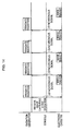
- Fig. 14 is a time chart showing the flow of image capturing operations in a case in which fluoroscopic imaging by pulse irradiation is designated.
- the console 42 transmits, to the radiation generator 34 and the electronic cassette 32, a synchronous signal at a period corresponding to the designated frame rate.
- the radiation generator 34 Each time the radiation generator 34 receives the synchronous signal, the radiation generator 34 generates and emits radiation at the tube voltage and tube current and for the irradiation time that correspond to the exposure conditions received from the console 42.
- the cassette controller 92 of the electronic cassette 32 controls the gate line driver 80 and causes on signals to be outputted from the gate line driver 80 to the respective gate lines 76 in order and line-by-line, and turns the respective TFTs 70, that are connected to the respective gate lines 76, on in order and line-by-line, and reads-out the image.
- the electric signals that have flowed-out to the respective data lines 78 of the radiation detector 60 are converted into digital image data at the signal processor 82, are stored in the image memory 90, and are transmitted to the console 42 by one image (frame) worth of data amount at a time.
- the image data that are transmitted to the console 42 are subjected, at the console 42, to image processings that effect various types of corrections, such as shading correction and the like, and are stored in the HDD 110.
- the image data stored in the HDD 110 is displayed on the display 100 for confirmation of the captured radiographic images and the like, and is transferred to the RIS server 14 and stored in the database 14A as well.
- the console 42 transmits instruction data that instructs the end of exposure to the radiation generator 34 and the electronic cassette 32. Due thereto, the radiation source 130 stops irradiation of the radiation, and the electronic cassette 32 ends the reading-out of images.
- the cassette controller 92 may carry out at least one of extending the charge accumulating time periods at the respective pixels 74, increasing the gain amount of the operation amplifier 84A, and image processing for making plural adjacent pixels 74 be one pixel.
- accelerations in directions of three axes are detected by the acceleration sensor 156 each predetermined time period (each 0.1 seconds in the present exemplary embodiment), and acceleration information (data), that expresses the detected accelerations in the three axial directions, is transmitted to the console 42.
- shaking threshold values are stored in advance in the HDD 110, and a judgment is made as to whether or not shaking has arisen by comparing the accelerations in the three axial directions with the threshold values.
- two shaking threshold values are stored.
- the first shaking threshold value is an amount of shaking of an extent such that the offset in the irradiated region of the radiation from the radiation generator 34 is small and image capturing does not fail.
- the second shaking threshold value is an amount of shaking of an extent such that the irradiated region of the radiation from the radiation generator 34 is greatly offset, and image capturing fails.
- the console 42 When the console 42 receives the acceleration information from the radiation generator 34, the console 42 executes erroneous irradiation preventing processing.
- Fig, 15 is a flowchart showing the flow of an erroneous irradiation preventing processing program that is executed as interruption processing by the CPU 104 of the console 42 at this time, This program also is stored in advance in a predetermined area of the ROM 106.
- step 400 of Fig. 15 a judgment is made as to whether or not any of the accelerations in the three axial directions that are expressed by the received acceleration data is greater than or equal to the first shaking threshold value. If the judgment is negative, the present erroneous irradiation preventing processing program ends, whereas if the judgment is affirmative, the routine proceeds to step 402.
- step 402 a judgment is made as to whether or not any of the accelerations in the three axial directions that are expressed by the received acceleration data is greater than or equal to the second shaking threshold value. If the judgment is negative, the routine moves on to step 404, whereas if the judgment is affirmative, the routine proceeds to step 406.
- step 404 a predetermined warning is started, and thereafter, the present erroneous irradiation preventing processing program ends.
- processing is carried out to display, on the display 100 of the console 42, a warning screen that urges caution.
- the present exemplary embodiment is not limited to the same.
- any other processing that can urge caution such as providing a buzzer at the console 42 and carrying out the processing of sounding the buzzer, or providing a speaker at the console 42 and carrying out the processing of issuing a voice message that urges caution from the speaker, or providing a warning lamp at the console 42 and carrying out the processing of lighting the warning lamp or causing the warning lamp to flash, or the like, or combinations thereof, may be utilized.
- step 406 after a predetermined irradiation prohibiting processing is executed, the present erroneous irradiation preventing processing program ends.
- processing that stops irradiation of the radiation X from the radiation source 130 is carried out with respect to the radiation generator 34, and processing for displaying, by the display 100 of the console 42, a presenting screen that expresses that irradiation of radiation is prohibited is carried out, and thereafter, processing that forcibly ends execution of the above-described radiographic image capturing processing program is carried out.
- processing that stops irradiation of the radiation X processing that transmits, to the radiation generator 34, instruction data for forcibly cutting-off the supply path of electric power for driving to the radiation source 130, is carried out.
- the exemplary embodiment is not limited to these, and other processings that can stop the irradiation of the radiation X by the radiation source 130, such as, for example, processing that transmits to the radiation generator 34 instruction data to stop irradiation of the radiation X by the radiation source 130, or the like, may be applied.
- the exemplary embodiment describes a case in which a structure having a C arm is used as the radiation generator 34, but the exemplary embodiment is not limited to the same.
- a movable radiation generator that does not have a C arm such as that disclosed in JP-A No. 2005-323673 for example, is applied.
- effects that are similar to those of the above-described exemplary embodiment can be achieved.
- the exemplary embodiment is not limited to the same.
- a structure in which only the radiation source 130 is moved by a moving mechanism in the radiographic image capturing room 44 may be applied as the radiation generator.
- the structure can be applied in the same way as in the above-described exemplary embodiment by deriving the distances of another object with respect to the radiation source 130 and the moving mechanism. Also in this case, effects that are similar to those of the above-described exemplary embodiment can be achieved.
- the exemplary embodiment describes a case in which the electronic cassette 32 is used independently without being attached to the radiation generator 34, but the exemplary embodiment is not limited to the same.
- the exemplary embodiment is not limited to the same.
- the minimum irradiated amount ensuring judgment processing program ( Fig. 10 ) a judgment is made as to whether or not the minimum irradiated amount needed for capturing of radiographic images can be ensured, and, in a case in which the minimum irradiated amount cannot be ensured, warning is given by displaying on the display 100 the fact that the minimum irradiated amount cannot be ensured.
- the exemplary embodiment is not limited to the same, and for example, the frame rate may be automatically switched to a frame rate at which the minimum irradiated amount can be ensured.
- the exemplary embodiment describes a case in which, in cases in which fluoroscopic imaging is designated as the image capturing mode, exposure conditions such as the frame rate, the tube voltage, the tube current and the like are designated to the operation panel 102.
- the exemplary embodiment is not limited to the same.
- the frame rate, the total amount of radiation that is permitted to be irradiated at the time of fluoroscopic imaging, and the planned image capturing time may be designated.
- data expressing the total amount of radiation that is permitted to be irradiated for each imaged region may be stored in advance in the HDD 110, and, when the imaged region is designated, the total amount of radiation that corresponds to the designated imaged region may be obtained from the stored data.
- FIG. 17 An example of a minimum irradiated amount ensuring judgment processing program is shown in Fig. 17 . Note that portions that are the same as in the above-described exemplary embodiment ( Fig. 10 ) are denoted by the same reference numerals, and description thereof is omitted.
- the irradiated amount of radiation per unit time is derived by dividing the permitted total amount of radiation by the planned image capturing time.
- the irradiated amount of radiation per one image is derived by multiplying the irradiation time of the radiation per one image, that was derived in step 300, by the irradiated amount of radiation per unit time that was derived in step 303.
- the frame rate may be switched to a frame rate at which the minimum irradiated amount per one image is obtained.
- control that prohibits the irradiation of radiation is applied as the control for preventing irradiation of radiation
- the exemplary embodiment is not limited to the same.
- control that delays the start timing of the irradiation of the radiation, control that reduces the irradiated amount of the radiation, or the like may be applied.
- effects that are similar to those of the above-described exemplary embodiment can be achieved.
- the above exemplary embodiment describes a case in which the acceleration sensor 156 is provided in a vicinity of the radiation source 130, but the exemplary embodiment is not limited to the same.
- the acceleration sensor 156 may be provided at the radiation source 130 itself. Effects that are similar to those of the above-described exemplary embodiment can be achieved in this case as well.
- the detecting means that detects the shaking is not limited to the acceleration sensor 156, and an azimuth sensor that detects changes in the azimuth may be applied and the shaking may be detected from the changes in the azimuth.
- encoders may be incorporated into the wheel 154 portions of the radiation generator 34 or the respective movable portions of the radiation generator 34, and shaking may be detected from the amounts of movement of the wheels 154 or the C arm 140 by using the encoders.
- a camera such as a visible light camera, an infrared ray camera or the like may be used. In this case, it is not absolutely necessary for the camera to be provided at the radiation generator 34, and, for example, the camera may be provided at the ceiling or the floor of the radiographic image capturing room 44.
- An example of the method for deriving the distance between the radiation generator 34 and another object in this case is a method applying a technique of providing the camera at the same position as the acceleration sensor 156 relating to the present exemplary embodiment, and continuously capturing a region that includes the surroundings of the radiation generator 34 by using the camera, and detecting changes in the image obtained by the image capturing.
- the structure of the RIS 10 (see Fig. 1 ), the structures of the radiographic image capturing room and the radiation generator 34 (see Fig. 2 ), the structure of the electronic cassette 32 (see Fig.3 ), and the structure of the image capturing system 18 (see Fig. 4 ) that are described in the above exemplary embodiment are examples.
Landscapes
- Health & Medical Sciences (AREA)
- Life Sciences & Earth Sciences (AREA)
- Medical Informatics (AREA)
- Engineering & Computer Science (AREA)
- Radiology & Medical Imaging (AREA)
- Molecular Biology (AREA)
- Biophysics (AREA)
- Nuclear Medicine, Radiotherapy & Molecular Imaging (AREA)
- Optics & Photonics (AREA)
- Pathology (AREA)
- Physics & Mathematics (AREA)
- Biomedical Technology (AREA)
- Heart & Thoracic Surgery (AREA)
- High Energy & Nuclear Physics (AREA)
- Surgery (AREA)
- Animal Behavior & Ethology (AREA)
- General Health & Medical Sciences (AREA)
- Public Health (AREA)
- Veterinary Medicine (AREA)
- Apparatus For Radiation Diagnosis (AREA)
- Radiography Using Non-Light Waves (AREA)
Claims (11)
- Système de capture d'images radiographiques (18) qui comprend :un dispositif de capture d'images radiographiques (60) capable d'effectuer une imagerie fluoroscopique en capturant des images radiographiques selon une vitesse de trame prédéterminée ;un dispositif d'irradiation (130) configuré pour effectuer soit une irradiation continue émise en continu par le dispositif d'irradiation, soit une irradiation par impulsions par rapport au dispositif de capture d'images radiographiques pendant l'imagerie fluoroscopique ; etun dispositif de commande qui possède un contrôleur de rayonnement (134) configuré pour contrôler ledit dispositif d'irradiation (130), caractérisé en ce que ledit contrôleur (134) est adapté pour contrôler ledit dispositif d'irradiation sur la base de ladite vitesse de trame afin que, lorsque ladite vitesse de trame, c'est-à-dire le nombre de trames par seconde, de l'imagerie fluoroscopique est inférieure ou égale à une valeur de seuil prédéterminée, le dispositif d'irradiation effectue une irradiation continue par rapport au dispositif de capture d'images radiographiques.
- Dispositif de capture d'images radiographiques selon la revendication 1, dans lequel
le dispositif de commande comprend en outre une section de sélection qui choisit si le dispositif d'irradiation effectue une irradiation par impulsions ou une irradiation continue, et
lorsque la vitesse de trame de l'imagerie fluoroscopique est inférieure ou égale à une première valeur de seuil de vitesse de trame, le contrôleur (134) est adapté pour recommander l'irradiation continue à la place de l'irradiation par impulsions à la section de sélection, et, lorsque la vitesse de trame de l'imagerie fluoroscopique est inférieure ou égale à une seconde valeur de seuil de vitesse de trame qui est inférieure à la première valeur de seuil de vitesse de trame, le contrôleur est adapté pour empêcher la sélection de l'irradiation par impulsions. - Système de capture d'images radiographiques selon la revendication 2, dans lequel la première valeur de seuil de vitesse de trame est de 15 fps à 60 fps, et la seconde valeur de seuil de vitesse de trame est de 5 fps à une valeur inférieure à la première valeur de seuil de vitesse de trame.
- Système de capture d'images radiographiques selon la revendication 3, dans lequel la première valeur de seuil de vitesse de trame est de 30 fps, et la seconde valeur de seuil de vitesse de trame est de 15 fps.
- Système de capture d'images radiographiques selon la revendication 1, dans lequel le contrôleur est adapté pour dériver une quantité d'irradiation par image à partir d'une durée d'irradiation par image à la vitesse de trame de l'imagerie fluoroscopique, et une quantité d'irradiation par unité de temps à partir du dispositif d'irradiation (130) et, lorsque la quantité d'irradiation dérivée par image est inférieure à une quantité d'irradiation minimum nécessaire pour capturer des images radiographiques, le contrôleur est adapté pour émettre une alerte ou pour modifier la vitesse de trame en une vitesse à laquelle une quantité d'irradiation minimum par image est obtenue.
- Système de capture d'images radiographiques selon la revendication 5, dans lequel le contrôleur (134) est adapté pour dériver la quantité d'irradiation par unité de temps à partir du dispositif d'irradiation (130) en divisant une quantité d'irradiation totale autorisée pour une zone imagée, c'est-à-dire l'objet d'une capture d'images, par une durée de capture d'image prévue.
- Système de capture d'images radiographiques selon la revendication 1, dans lequel
le dispositif de capture d'images radiographiques (60) est en outre capable d'effectuer une capture d'images fixes, et
lorsqu'une capture d'images fixes doit être effectuée, le contrôleur (134) est adapté pour définir un niveau de priorité d'irradiation par impulsions comme étant supérieur à un niveau de priorité d'irradiation continue. - Système de capture d'images radiographiques selon la revendication 1, dans lequel le dispositif d'irradiation (130) effectue une irradiation continue avec une quantité d'irradiation par unité de temps inférieure à celle existant lorsque le dispositif d'irradiation effectue une irradiation par impulsions.
- Système de capture d'images radiographiques selon la revendication 8, dans lequel le dispositif de capture d'images radiographiques comprend :un détecteur de rayonnement (60) au niveau duquel une pluralité de pixels, qui génèrent une charge à la suite de leur irradiation et qui accumulent ladite charge, sont prévus sous une forme en deux dimensions, et qui délivre la charge accumulée au niveau desdits pixels respectifs sous la forme d'un signal électrique ;un amplificateur qui amplifie le signal électrique délivré par le détecteur de rayonnement ; etun contrôleur de dispositif de capture d'images (92) qui, en cas d'irradiation continue, effectue au moins l'une des opérations suivantes : la prolongation d'une durée d'accumulation de charge au niveau desdits pixels respectifs de façon à ce qu'elle soit supérieure à celle de l'irradiation par impulsions ; l'augmentation d'une quantité de gain dudit amplificateur de façon à ce qu'elle soit supérieure à celle de l'irradiation par impulsions ; et un traitement d'image qui combine une pluralité de pixels adjacents en un seul pixel.
- Système de capture d'images radiographiques selon la revendication 1, qui comprend en outre une section de détection qui détecte tout tremblement du dispositif d'irradiation,
dans lequel, lorsque la quantité de tremblement du dispositif d'irradiation détectée par ladite section de détection pendant une imagerie fluoroscopique est supérieure ou égale à une première valeur de seuil de tremblement, le contrôleur est adapté pour émettre une alerte, et, lorsque ladite quantité de tremblement est supérieure ou égale à une seconde valeur de seuil de tremblement supérieure à ladite première valeur de seuil de tremblement, le contrôleur arrête l'irradiation par le dispositif d'irradiation. - Système de capture d'images radiographiques selon la revendication 10, dans lequel le contrôleur émet l'alerte et arrête l'irradiation lorsque la section de détection détecte un tremblement du dispositif de détection d'irradiation pendant l'imagerie fluoroscopique par irradiation continue.
Applications Claiming Priority (2)
| Application Number | Priority Date | Filing Date | Title |
|---|---|---|---|
| JP2009298780 | 2009-12-28 | ||
| JP2010277139A JP5616211B2 (ja) | 2009-12-28 | 2010-12-13 | 放射線画像撮影システム |
Publications (2)
| Publication Number | Publication Date |
|---|---|
| EP2338418A1 EP2338418A1 (fr) | 2011-06-29 |
| EP2338418B1 true EP2338418B1 (fr) | 2012-11-14 |
Family
ID=43661983
Family Applications (1)
| Application Number | Title | Priority Date | Filing Date |
|---|---|---|---|
| EP10196520A Not-in-force EP2338418B1 (fr) | 2009-12-28 | 2010-12-22 | Système de capture d'images radiographiques |
Country Status (4)
| Country | Link |
|---|---|
| US (1) | US8363786B2 (fr) |
| EP (1) | EP2338418B1 (fr) |
| JP (1) | JP5616211B2 (fr) |
| CN (1) | CN102106737B (fr) |
Families Citing this family (22)
| Publication number | Priority date | Publication date | Assignee | Title |
|---|---|---|---|---|
| WO2013047069A1 (fr) * | 2011-09-26 | 2013-04-04 | 富士フイルム株式会社 | Système de capture d'image d'image radiographique, procédé et programme de commande de capture d'image d'image radiographique |
| JP5490084B2 (ja) * | 2011-12-22 | 2014-05-14 | 富士フイルム株式会社 | 放射線画像検出器、放射線画像撮像装置、及び放射線画像撮像システム |
| WO2013125325A1 (fr) * | 2012-02-23 | 2013-08-29 | 富士フイルム株式会社 | Dispositif de radiographie, système de radiographie, procédé de commande de dispositif de radiographie, et programme de commande de dispositif de radiographie |
| JP6021403B2 (ja) * | 2012-04-19 | 2016-11-09 | キヤノン株式会社 | 放射線撮像装置 |
| JP2014039796A (ja) * | 2012-07-23 | 2014-03-06 | Fujifilm Corp | 検出限界導出装置、放射線検出装置、放射線画像撮影システム、検出限界導出プログラム、及び検出限界導出方法 |
| WO2014055488A2 (fr) * | 2012-10-02 | 2014-04-10 | Carestream Health, Inc. | Imagerie sans fil à cadence rapide de prise d'image |
| JP6070140B2 (ja) * | 2012-12-11 | 2017-02-01 | コニカミノルタ株式会社 | 放射線画像撮影システム |
| WO2014192960A1 (fr) * | 2013-05-31 | 2014-12-04 | 株式会社 東芝 | Dispositif de diagnostic à rayons x |
| JP6127850B2 (ja) * | 2013-09-13 | 2017-05-17 | コニカミノルタ株式会社 | 可搬型放射線撮影システム |
| JP6050206B2 (ja) * | 2013-09-17 | 2016-12-21 | 富士フイルム株式会社 | 放射線撮影システム及び通信環境制御装置 |
| US9795347B2 (en) * | 2013-10-24 | 2017-10-24 | Institute Of Nuclear Energy Research Atomic Energy Council, Executive Yuan | Scanning system for three-dimensional imaging |
| WO2016203282A1 (fr) | 2015-06-18 | 2016-12-22 | The Nielsen Company (Us), Llc | Procédés et appareil pour capturer des photographies à l'aide de dispositifs mobiles |
| US10806424B2 (en) | 2016-09-30 | 2020-10-20 | Varex Imaging Corporation | Imager with bump detection |
| JP6933016B2 (ja) | 2017-06-22 | 2021-09-08 | コニカミノルタ株式会社 | 放射線画像撮影システム |
| JP6950483B2 (ja) * | 2017-11-20 | 2021-10-13 | コニカミノルタ株式会社 | 動態撮影システム |
| JP2019126523A (ja) * | 2018-01-24 | 2019-08-01 | コニカミノルタ株式会社 | 放射線撮影装置及び放射線撮影システム |
| US10758197B2 (en) | 2018-06-15 | 2020-09-01 | Carestream Health, Inc. | Radiation tracking for portable fluoroscopy X-ray imaging system |
| JP7251088B2 (ja) * | 2018-10-03 | 2023-04-04 | コニカミノルタ株式会社 | 放射線撮影制御装置、放射線撮影システム及び放射線画像撮影方法 |
| JP7292952B2 (ja) * | 2019-04-25 | 2023-06-19 | キヤノン株式会社 | 放射線撮影システム、照射制御装置及び放射線撮影システムの制御方法 |
| JP2021087528A (ja) * | 2019-12-03 | 2021-06-10 | コニカミノルタ株式会社 | 放射線撮影システム、撮影制御装置及びプログラム |
| JP2022085288A (ja) * | 2020-11-27 | 2022-06-08 | キヤノン株式会社 | 放射線撮像装置、放射線撮像システム、放射線撮像装置の制御方法、及び、そのプログラム |
| JP7650306B2 (ja) * | 2023-02-22 | 2025-03-24 | キヤノン株式会社 | 情報処理装置、情報処理方法、及びプログラム |
Family Cites Families (9)
| Publication number | Priority date | Publication date | Assignee | Title |
|---|---|---|---|---|
| US5119409A (en) * | 1990-12-28 | 1992-06-02 | Fischer Imaging Corporation | Dynamic pulse control for fluoroscopy |
| JPH06114044A (ja) * | 1992-09-30 | 1994-04-26 | Shimadzu Corp | X線透視装置 |
| JPH06292082A (ja) * | 1993-03-31 | 1994-10-18 | Shimadzu Corp | X線撮像装置 |
| JP2765482B2 (ja) * | 1994-05-30 | 1998-06-18 | 株式会社島津製作所 | X線画像処理システム |
| US5917882A (en) * | 1996-11-29 | 1999-06-29 | Continental X-Ray Corporation | Radiographic/fluoroscopic imaging system with reduced patient dose and faster transitions between radiographic and fluoroscopic modes |
| JP2005323673A (ja) | 2004-05-12 | 2005-11-24 | Shimadzu Corp | 移動式x線撮影装置 |
| JP5017014B2 (ja) * | 2007-08-09 | 2012-09-05 | キヤノン株式会社 | 放射線撮影装置及びその制御方法 |
| JP5422114B2 (ja) * | 2007-12-06 | 2014-02-19 | 株式会社東芝 | X線診断装置 |
| JP5127492B2 (ja) | 2008-02-08 | 2013-01-23 | キヤノン株式会社 | ワイヤレスx線透視システム及びそのユニット間の同期方法、コンピュータプログラム |
-
2010
- 2010-12-13 JP JP2010277139A patent/JP5616211B2/ja not_active Expired - Fee Related
- 2010-12-22 EP EP10196520A patent/EP2338418B1/fr not_active Not-in-force
- 2010-12-27 CN CN201010623083.1A patent/CN102106737B/zh not_active Expired - Fee Related
- 2010-12-28 US US12/979,370 patent/US8363786B2/en not_active Expired - Fee Related
Also Published As
| Publication number | Publication date |
|---|---|
| EP2338418A1 (fr) | 2011-06-29 |
| JP2011152406A (ja) | 2011-08-11 |
| JP5616211B2 (ja) | 2014-10-29 |
| CN102106737B (zh) | 2014-11-05 |
| US8363786B2 (en) | 2013-01-29 |
| CN102106737A (zh) | 2011-06-29 |
| US20110158385A1 (en) | 2011-06-30 |
Similar Documents
| Publication | Publication Date | Title |
|---|---|---|
| EP2338418B1 (fr) | Système de capture d'images radiographiques | |
| US8358740B2 (en) | Radiographic image capturing system | |
| US8461543B2 (en) | Radiographic image capturing system | |
| US9020097B2 (en) | Radiographic imaging system | |
| JP5587356B2 (ja) | 放射線撮影システム、放射線撮影システムの駆動制御方法および駆動制御プログラム、並びに放射線画像検出装置 | |
| JP5797630B2 (ja) | 放射線画像撮影装置、画素値取得方法およびプログラム | |
| JP5137763B2 (ja) | 放射線検出装置及び放射線画像撮影システム | |
| US8546777B2 (en) | Radiographic image capturing device | |
| US20100078583A1 (en) | Radiation image capturing system | |
| JP5500933B2 (ja) | 放射線画像撮影装置、放射線画像撮影システム、およびプログラム | |
| JP5322826B2 (ja) | 放射線画像撮影支援装置、放射線画像撮影装置及びプログラム | |
| US20100207032A1 (en) | Radiographic image capture system, radiation generation device, image capture control device and radiographic image capture device | |
| JP2010075677A (ja) | 放射線画像撮影装置、及び画像処理装置 | |
| JP5869082B2 (ja) | 放射線画像撮影システム | |
| JP2010136063A (ja) | 放射線画像撮影装置 | |
| JP2005006888A (ja) | 放射線画像撮影装置 | |
| JP2017099783A (ja) | 移動型放射線撮影装置 | |
| JP2010161624A (ja) | 放射線画像撮影装置、放射線画撮影システム、及び画像処理装置 | |
| JP2014090863A (ja) | 放射線画像撮影システムおよび自動露出制御方法 | |
| JP5398461B2 (ja) | 放射線画像撮影装置、放射線画像撮影システム、放射線画像撮影装置の制御方法、及び制御装置 | |
| JP2011177450A (ja) | 放射線画像撮影システム、放射線画像撮影装置、およびプログラム | |
| JP2014090862A (ja) | 放射線画像撮影システム、放射線画像撮影装置および自動露出制御方法 | |
| JP2011104089A (ja) | 放射線画像撮影システム | |
| JP2010082186A (ja) | 撮影制御装置 |
Legal Events
| Date | Code | Title | Description |
|---|---|---|---|
| PUAI | Public reference made under article 153(3) epc to a published international application that has entered the european phase |
Free format text: ORIGINAL CODE: 0009012 |
|
| AK | Designated contracting states |
Kind code of ref document: A1 Designated state(s): AL AT BE BG CH CY CZ DE DK EE ES FI FR GB GR HR HU IE IS IT LI LT LU LV MC MK MT NL NO PL PT RO RS SE SI SK SM TR |
|
| AX | Request for extension of the european patent |
Extension state: BA ME |
|
| 17P | Request for examination filed |
Effective date: 20111207 |
|
| GRAP | Despatch of communication of intention to grant a patent |
Free format text: ORIGINAL CODE: EPIDOSNIGR1 |
|
| RIN1 | Information on inventor provided before grant (corrected) |
Inventor name: YOSHIDA, YUTAKA Inventor name: IWAKIRI, NAOTO Inventor name: NAKATSUGAWA, HARUYASU Inventor name: NISHINO, NAOYUKI Inventor name: OHTA, YASUNORI |
|
| GRAS | Grant fee paid |
Free format text: ORIGINAL CODE: EPIDOSNIGR3 |
|
| GRAA | (expected) grant |
Free format text: ORIGINAL CODE: 0009210 |
|
| AK | Designated contracting states |
Kind code of ref document: B1 Designated state(s): AL AT BE BG CH CY CZ DE DK EE ES FI FR GB GR HR HU IE IS IT LI LT LU LV MC MK MT NL NO PL PT RO RS SE SI SK SM TR |
|
| REG | Reference to a national code |
Ref country code: GB Ref legal event code: FG4D |
|
| REG | Reference to a national code |
Ref country code: AT Ref legal event code: REF Ref document number: 583530 Country of ref document: AT Kind code of ref document: T Effective date: 20121115 Ref country code: CH Ref legal event code: EP |
|
| REG | Reference to a national code |
Ref country code: IE Ref legal event code: FG4D |
|
| REG | Reference to a national code |
Ref country code: DE Ref legal event code: R096 Ref document number: 602010003615 Country of ref document: DE Effective date: 20130110 |
|
| REG | Reference to a national code |
Ref country code: NL Ref legal event code: T3 |
|
| REG | Reference to a national code |
Ref country code: AT Ref legal event code: MK05 Ref document number: 583530 Country of ref document: AT Kind code of ref document: T Effective date: 20121114 |
|
| REG | Reference to a national code |
Ref country code: LT Ref legal event code: MG4D |
|
| PG25 | Lapsed in a contracting state [announced via postgrant information from national office to epo] |
Ref country code: ES Free format text: LAPSE BECAUSE OF FAILURE TO SUBMIT A TRANSLATION OF THE DESCRIPTION OR TO PAY THE FEE WITHIN THE PRESCRIBED TIME-LIMIT Effective date: 20130225 Ref country code: LT Free format text: LAPSE BECAUSE OF FAILURE TO SUBMIT A TRANSLATION OF THE DESCRIPTION OR TO PAY THE FEE WITHIN THE PRESCRIBED TIME-LIMIT Effective date: 20121114 Ref country code: SE Free format text: LAPSE BECAUSE OF FAILURE TO SUBMIT A TRANSLATION OF THE DESCRIPTION OR TO PAY THE FEE WITHIN THE PRESCRIBED TIME-LIMIT Effective date: 20121114 Ref country code: NO Free format text: LAPSE BECAUSE OF FAILURE TO SUBMIT A TRANSLATION OF THE DESCRIPTION OR TO PAY THE FEE WITHIN THE PRESCRIBED TIME-LIMIT Effective date: 20130214 Ref country code: FI Free format text: LAPSE BECAUSE OF FAILURE TO SUBMIT A TRANSLATION OF THE DESCRIPTION OR TO PAY THE FEE WITHIN THE PRESCRIBED TIME-LIMIT Effective date: 20121114 Ref country code: HR Free format text: LAPSE BECAUSE OF FAILURE TO SUBMIT A TRANSLATION OF THE DESCRIPTION OR TO PAY THE FEE WITHIN THE PRESCRIBED TIME-LIMIT Effective date: 20121114 |
|
| PG25 | Lapsed in a contracting state [announced via postgrant information from national office to epo] |
Ref country code: PL Free format text: LAPSE BECAUSE OF FAILURE TO SUBMIT A TRANSLATION OF THE DESCRIPTION OR TO PAY THE FEE WITHIN THE PRESCRIBED TIME-LIMIT Effective date: 20121114 Ref country code: LV Free format text: LAPSE BECAUSE OF FAILURE TO SUBMIT A TRANSLATION OF THE DESCRIPTION OR TO PAY THE FEE WITHIN THE PRESCRIBED TIME-LIMIT Effective date: 20121114 Ref country code: BE Free format text: LAPSE BECAUSE OF FAILURE TO SUBMIT A TRANSLATION OF THE DESCRIPTION OR TO PAY THE FEE WITHIN THE PRESCRIBED TIME-LIMIT Effective date: 20121114 Ref country code: PT Free format text: LAPSE BECAUSE OF FAILURE TO SUBMIT A TRANSLATION OF THE DESCRIPTION OR TO PAY THE FEE WITHIN THE PRESCRIBED TIME-LIMIT Effective date: 20130314 Ref country code: SI Free format text: LAPSE BECAUSE OF FAILURE TO SUBMIT A TRANSLATION OF THE DESCRIPTION OR TO PAY THE FEE WITHIN THE PRESCRIBED TIME-LIMIT Effective date: 20121114 Ref country code: GR Free format text: LAPSE BECAUSE OF FAILURE TO SUBMIT A TRANSLATION OF THE DESCRIPTION OR TO PAY THE FEE WITHIN THE PRESCRIBED TIME-LIMIT Effective date: 20130215 |
|
| PG25 | Lapsed in a contracting state [announced via postgrant information from national office to epo] |
Ref country code: AT Free format text: LAPSE BECAUSE OF FAILURE TO SUBMIT A TRANSLATION OF THE DESCRIPTION OR TO PAY THE FEE WITHIN THE PRESCRIBED TIME-LIMIT Effective date: 20121114 |
|
| PG25 | Lapsed in a contracting state [announced via postgrant information from national office to epo] |
Ref country code: BG Free format text: LAPSE BECAUSE OF FAILURE TO SUBMIT A TRANSLATION OF THE DESCRIPTION OR TO PAY THE FEE WITHIN THE PRESCRIBED TIME-LIMIT Effective date: 20130214 Ref country code: EE Free format text: LAPSE BECAUSE OF FAILURE TO SUBMIT A TRANSLATION OF THE DESCRIPTION OR TO PAY THE FEE WITHIN THE PRESCRIBED TIME-LIMIT Effective date: 20121114 Ref country code: DK Free format text: LAPSE BECAUSE OF FAILURE TO SUBMIT A TRANSLATION OF THE DESCRIPTION OR TO PAY THE FEE WITHIN THE PRESCRIBED TIME-LIMIT Effective date: 20121114 Ref country code: SK Free format text: LAPSE BECAUSE OF FAILURE TO SUBMIT A TRANSLATION OF THE DESCRIPTION OR TO PAY THE FEE WITHIN THE PRESCRIBED TIME-LIMIT Effective date: 20121114 Ref country code: RS Free format text: LAPSE BECAUSE OF FAILURE TO SUBMIT A TRANSLATION OF THE DESCRIPTION OR TO PAY THE FEE WITHIN THE PRESCRIBED TIME-LIMIT Effective date: 20121114 Ref country code: CZ Free format text: LAPSE BECAUSE OF FAILURE TO SUBMIT A TRANSLATION OF THE DESCRIPTION OR TO PAY THE FEE WITHIN THE PRESCRIBED TIME-LIMIT Effective date: 20121114 Ref country code: MC Free format text: LAPSE BECAUSE OF NON-PAYMENT OF DUE FEES Effective date: 20121231 |
|
| PG25 | Lapsed in a contracting state [announced via postgrant information from national office to epo] |
Ref country code: IT Free format text: LAPSE BECAUSE OF FAILURE TO SUBMIT A TRANSLATION OF THE DESCRIPTION OR TO PAY THE FEE WITHIN THE PRESCRIBED TIME-LIMIT Effective date: 20121114 Ref country code: RO Free format text: LAPSE BECAUSE OF FAILURE TO SUBMIT A TRANSLATION OF THE DESCRIPTION OR TO PAY THE FEE WITHIN THE PRESCRIBED TIME-LIMIT Effective date: 20121114 |
|
| PLBE | No opposition filed within time limit |
Free format text: ORIGINAL CODE: 0009261 |
|
| STAA | Information on the status of an ep patent application or granted ep patent |
Free format text: STATUS: NO OPPOSITION FILED WITHIN TIME LIMIT |
|
| REG | Reference to a national code |
Ref country code: IE Ref legal event code: MM4A |
|
| 26N | No opposition filed |
Effective date: 20130815 |
|
| PG25 | Lapsed in a contracting state [announced via postgrant information from national office to epo] |
Ref country code: IE Free format text: LAPSE BECAUSE OF NON-PAYMENT OF DUE FEES Effective date: 20121222 |
|
| PG25 | Lapsed in a contracting state [announced via postgrant information from national office to epo] |
Ref country code: AL Free format text: LAPSE BECAUSE OF FAILURE TO SUBMIT A TRANSLATION OF THE DESCRIPTION OR TO PAY THE FEE WITHIN THE PRESCRIBED TIME-LIMIT Effective date: 20121114 Ref country code: CY Free format text: LAPSE BECAUSE OF FAILURE TO SUBMIT A TRANSLATION OF THE DESCRIPTION OR TO PAY THE FEE WITHIN THE PRESCRIBED TIME-LIMIT Effective date: 20121114 Ref country code: MT Free format text: LAPSE BECAUSE OF FAILURE TO SUBMIT A TRANSLATION OF THE DESCRIPTION OR TO PAY THE FEE WITHIN THE PRESCRIBED TIME-LIMIT Effective date: 20121114 |
|
| REG | Reference to a national code |
Ref country code: DE Ref legal event code: R097 Ref document number: 602010003615 Country of ref document: DE Effective date: 20130815 |
|
| PG25 | Lapsed in a contracting state [announced via postgrant information from national office to epo] |
Ref country code: TR Free format text: LAPSE BECAUSE OF FAILURE TO SUBMIT A TRANSLATION OF THE DESCRIPTION OR TO PAY THE FEE WITHIN THE PRESCRIBED TIME-LIMIT Effective date: 20121114 |
|
| PG25 | Lapsed in a contracting state [announced via postgrant information from national office to epo] |
Ref country code: LU Free format text: LAPSE BECAUSE OF NON-PAYMENT OF DUE FEES Effective date: 20121222 Ref country code: SM Free format text: LAPSE BECAUSE OF FAILURE TO SUBMIT A TRANSLATION OF THE DESCRIPTION OR TO PAY THE FEE WITHIN THE PRESCRIBED TIME-LIMIT Effective date: 20121114 |
|
| PG25 | Lapsed in a contracting state [announced via postgrant information from national office to epo] |
Ref country code: HU Free format text: LAPSE BECAUSE OF FAILURE TO SUBMIT A TRANSLATION OF THE DESCRIPTION OR TO PAY THE FEE WITHIN THE PRESCRIBED TIME-LIMIT Effective date: 20101222 |
|
| PG25 | Lapsed in a contracting state [announced via postgrant information from national office to epo] |
Ref country code: MK Free format text: LAPSE BECAUSE OF FAILURE TO SUBMIT A TRANSLATION OF THE DESCRIPTION OR TO PAY THE FEE WITHIN THE PRESCRIBED TIME-LIMIT Effective date: 20121114 |
|
| REG | Reference to a national code |
Ref country code: CH Ref legal event code: PL |
|
| GBPC | Gb: european patent ceased through non-payment of renewal fee |
Effective date: 20141222 |
|
| PG25 | Lapsed in a contracting state [announced via postgrant information from national office to epo] |
Ref country code: LI Free format text: LAPSE BECAUSE OF NON-PAYMENT OF DUE FEES Effective date: 20141231 Ref country code: CH Free format text: LAPSE BECAUSE OF NON-PAYMENT OF DUE FEES Effective date: 20141231 Ref country code: GB Free format text: LAPSE BECAUSE OF NON-PAYMENT OF DUE FEES Effective date: 20141222 |
|
| REG | Reference to a national code |
Ref country code: FR Ref legal event code: PLFP Year of fee payment: 6 |
|
| PG25 | Lapsed in a contracting state [announced via postgrant information from national office to epo] |
Ref country code: IS Free format text: LAPSE BECAUSE OF FAILURE TO SUBMIT A TRANSLATION OF THE DESCRIPTION OR TO PAY THE FEE WITHIN THE PRESCRIBED TIME-LIMIT Effective date: 20121114 |
|
| REG | Reference to a national code |
Ref country code: FR Ref legal event code: PLFP Year of fee payment: 7 |
|
| REG | Reference to a national code |
Ref country code: DE Ref legal event code: R082 Ref document number: 602010003615 Country of ref document: DE Representative=s name: KLUNKER IP PATENTANWAELTE PARTG MBB, DE |
|
| REG | Reference to a national code |
Ref country code: FR Ref legal event code: PLFP Year of fee payment: 8 |
|
| PGFP | Annual fee paid to national office [announced via postgrant information from national office to epo] |
Ref country code: DE Payment date: 20191210 Year of fee payment: 10 Ref country code: NL Payment date: 20191114 Year of fee payment: 10 |
|
| PGFP | Annual fee paid to national office [announced via postgrant information from national office to epo] |
Ref country code: FR Payment date: 20191115 Year of fee payment: 10 |
|
| REG | Reference to a national code |
Ref country code: DE Ref legal event code: R119 Ref document number: 602010003615 Country of ref document: DE |
|
| REG | Reference to a national code |
Ref country code: NL Ref legal event code: MM Effective date: 20210101 |
|
| PG25 | Lapsed in a contracting state [announced via postgrant information from national office to epo] |
Ref country code: NL Free format text: LAPSE BECAUSE OF NON-PAYMENT OF DUE FEES Effective date: 20210101 |
|
| PG25 | Lapsed in a contracting state [announced via postgrant information from national office to epo] |
Ref country code: FR Free format text: LAPSE BECAUSE OF NON-PAYMENT OF DUE FEES Effective date: 20201231 |
|
| PG25 | Lapsed in a contracting state [announced via postgrant information from national office to epo] |
Ref country code: DE Free format text: LAPSE BECAUSE OF NON-PAYMENT OF DUE FEES Effective date: 20210701 |