EP2339437A2 - Dispositif d'écran tactile amélioré - Google Patents
Dispositif d'écran tactile amélioré Download PDFInfo
- Publication number
- EP2339437A2 EP2339437A2 EP10193285A EP10193285A EP2339437A2 EP 2339437 A2 EP2339437 A2 EP 2339437A2 EP 10193285 A EP10193285 A EP 10193285A EP 10193285 A EP10193285 A EP 10193285A EP 2339437 A2 EP2339437 A2 EP 2339437A2
- Authority
- EP
- European Patent Office
- Prior art keywords
- operable
- radiation
- light intensity
- sensing plane
- sensing
- Prior art date
- Legal status (The legal status is an assumption and is not a legal conclusion. Google has not performed a legal analysis and makes no representation as to the accuracy of the status listed.)
- Withdrawn
Links
Images

Classifications
-
- G—PHYSICS
- G06—COMPUTING OR CALCULATING; COUNTING
- G06F—ELECTRIC DIGITAL DATA PROCESSING
- G06F3/00—Input arrangements for transferring data to be processed into a form capable of being handled by the computer; Output arrangements for transferring data from processing unit to output unit, e.g. interface arrangements
- G06F3/01—Input arrangements or combined input and output arrangements for interaction between user and computer
- G06F3/03—Arrangements for converting the position or the displacement of a member into a coded form
- G06F3/041—Digitisers, e.g. for touch screens or touch pads, characterised by the transducing means
- G06F3/042—Digitisers, e.g. for touch screens or touch pads, characterised by the transducing means by opto-electronic means
- G06F3/0428—Digitisers, e.g. for touch screens or touch pads, characterised by the transducing means by opto-electronic means by sensing at the edges of the touch surface the interruption of optical paths, e.g. an illumination plane, parallel to the touch surface which may be virtual
-
- G—PHYSICS
- G06—COMPUTING OR CALCULATING; COUNTING
- G06F—ELECTRIC DIGITAL DATA PROCESSING
- G06F3/00—Input arrangements for transferring data to be processed into a form capable of being handled by the computer; Output arrangements for transferring data from processing unit to output unit, e.g. interface arrangements
- G06F3/01—Input arrangements or combined input and output arrangements for interaction between user and computer
- G06F3/03—Arrangements for converting the position or the displacement of a member into a coded form
- G06F3/041—Digitisers, e.g. for touch screens or touch pads, characterised by the transducing means
- G06F3/0416—Control or interface arrangements specially adapted for digitisers
- G06F3/04166—Details of scanning methods, e.g. sampling time, grouping of sub areas or time sharing with display driving
-
- G—PHYSICS
- G06—COMPUTING OR CALCULATING; COUNTING
- G06F—ELECTRIC DIGITAL DATA PROCESSING
- G06F3/00—Input arrangements for transferring data to be processed into a form capable of being handled by the computer; Output arrangements for transferring data from processing unit to output unit, e.g. interface arrangements
- G06F3/01—Input arrangements or combined input and output arrangements for interaction between user and computer
- G06F3/048—Interaction techniques based on graphical user interfaces [GUI]
- G06F3/0487—Interaction techniques based on graphical user interfaces [GUI] using specific features provided by the input device, e.g. functions controlled by the rotation of a mouse with dual sensing arrangements, or of the nature of the input device, e.g. tap gestures based on pressure sensed by a digitiser
- G06F3/0488—Interaction techniques based on graphical user interfaces [GUI] using specific features provided by the input device, e.g. functions controlled by the rotation of a mouse with dual sensing arrangements, or of the nature of the input device, e.g. tap gestures based on pressure sensed by a digitiser using a touch-screen or digitiser, e.g. input of commands through traced gestures
-
- G—PHYSICS
- G06—COMPUTING OR CALCULATING; COUNTING
- G06F—ELECTRIC DIGITAL DATA PROCESSING
- G06F2203/00—Indexing scheme relating to G06F3/00 - G06F3/048
- G06F2203/041—Indexing scheme relating to G06F3/041 - G06F3/045
- G06F2203/04101—2.5D-digitiser, i.e. digitiser detecting the X/Y position of the input means, finger or stylus, also when it does not touch, but is proximate to the digitiser's interaction surface and also measures the distance of the input means within a short range in the Z direction, possibly with a separate measurement setup
Definitions
- This application relates to touch sensitive screens and in particular touch sensitive screens capable of resolving simultaneous touches at multiple points which are also pressure sensitive.
- Touch screen systems implementing both multi-touch and pressure sensitive functionality are rare due to the difficulty in solving technical problems presented while maintaining cost-effectiveness.
- an apparatus comprising a surface, at least one radiation source and at least one corresponding sensor operable such that radiation from said radiation source follows an optical path to said sensor that is substantially parallel with said surface within a sensing plane, such that said apparatus can determine the position on said surface of one or more touches by an object by sensing radiation levels in said sensing plane, wherein said apparatus is further operable to determine the relative pressure applied to the surface by a touch based upon a parameter related to the approaching speed of the touching object through the sensing plane.
- Said apparatus may be operable such that measurements made to determine the approaching speed of the touching object through the sensing plane are made at a single height above said surface.
- Said apparatus may also comprise a display, said surface being the display screen.
- the approaching speed of the touching object may be determined by determination of the rate of change of said parameter from two or more frames imaged between the time said object enters the sensing plane and the time it touches the surface.
- Said parameter may comprise light intensity, and specifically the light intensity on the portion of the sensor affected by the touching object.
- Said sensor may comprise an array of individually addressed pixels and said device may be operable to determine the point of lowest intensity and to monitor movement of this point of lowest intensity during said two or more successive frames.
- said device may be operable to determine said rate of change of intensity from the rate of change of the slope at one or more points on a light intensity profile across said array and/or the rate of change of the width between pixels registering the same intensity levels at one or more points on said light intensity profile.
- one measurement point may be the midpoint between a touch threshold corresponding with the sensing plane and a minimum touch point corresponding with the display surface.
- Said device may comprise said at least one radiation source and said at least one corresponding sensor arranged to emit in and detect radiation from said sensing plane.
- There may be first and second sets of radiation sources, each with corresponding sensors, both sets of radiation sourced emitting radiation in the sensing plan, said first set emitting radiation in a direction perpendicular to the second set.
- Said radiation sources and sensors may work together in either absorption, retro-reflective or imaging modes. "Sets" of radiation sources and sensors may include a single radiation source and/or sensor.
- Said device may be operable to offset the integration phases of said first set of radiation sources and corresponding sensors in relation to said second set. Said offsetting should be such that only one of said first and second sets of radiation sources is turned on, and integration only performed on data from the corresponding set of sensors, at any one time.
- both of said offset integration phases for said first and second sets of radiation sources and corresponding sensors should be performed in a total timeframe similar to that when performing said phases simultaneously.
- said single integration phase speed may be substantially doubled in comparison to that practicable should integration be simultaneously performed on data from both sets of sensors
- Said touch sensitive surface may be separately sensitive to two or more simultaneous touches, and may be able to determine each position of said two or more simultaneous touches.
- an apparatus comprising a surface and first and second sets of radiation sources each with corresponding sensors, said radiation sources being arranged to emit radiation in a single sensing plane substantially parallel with said surface, said first set being operable to emit radiation perpendicular to the second set, such that said device can determine by sensing radiation levels in a sensing plane parallel with said surface, the position on said surface, of one or more touches by an object, wherein said device is operable to offset the integration phases of said first set of radiation sources and corresponding sensors, in relation to said second set.
- Said apparatus may also comprise a display, said surface being the display screen.
- Said apparatus may be operable such that radiation from said radiation sources follows an optical path to their corresponding sensor that is substantially parallel with said surface within the sensing plane. Said apparatus may be operable such that measurements made to determine the approaching speed of the touching object through the sensing plane are made at a single height above said surface.
- Said offsetting should be such that only one of said first and second sets of radiation sources is turned on, and integration only performed on data from the corresponding set of sensors, at any one time.
- Both of said offset integration phases for said first and second sets of radiation sources and corresponding sensors may be performed in a total timeframe similar to that when performing said phases simultaneously.
- said single integration phase speed may be substantially doubled in comparison to that practicable should integration be simultaneously performed on data from both sets of sensors
- Said radiation sources and sensors may work together in either absorption, retro-reflective or imaging modes.
- Said surface may be separately sensitive to two or more simultaneous touches, and may be able to determine each position of said two or more simultaneous touches.
- a method of determining the relative pressure applied to a surface of an apparatus which determines the presence and position of one or more touches comprising:
- Measurements made to determine the approaching speed of the touching object through the sensing plane may be made at a single height above said surface.
- Said parameter may comprise light intensity.
- the approaching speed of the touching object may be determined by determination of the rate of change of said parameter from two or more frames imaged between the time said object enters the sensing plane and the time it touches the surface.
- Said rate of change of light intensity may be determined from the rate of change of the slope at one or more points on a light intensity profile.
- Said rate of change of light intensity may be determined from the rate of change of the width between pixels registering the same intensity levels at one or more points on a light intensity profile across said array.
- the approaching speed of the touching object may be determined by determining the point of lowest intensity and movement of this point of lowest intensity may be monitored during said two or more successive frames.
- Integration of a first set of imaging data from one direction in the sensing plane and a second set of imaging data from a second, perpendicular, direction in the imaging plane may be offset such that integration may be performed on only one set of data at any one time.
- Integration of both sets of data may be performed in a total timeframe similar to that when performing said phases simultaneously.
- a single integration phase speed may be substantially doubled in comparison to that practicable should integration be simultaneously performed on data from both sets of sensors.
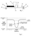
- Figure 1 shows a touch sensitive screen arrangement. It shows a screen surface 100, a contacting object 110 (such as a finger), the z-plane detection limit 120, the finger's shadow 130, the illumination source (an LED in this example) 140, illumination optics 150, light beam 160, the imaging optics 170 and sensor pixel array 180.
- the system actually consists of two sensor arrays 180X, 180Y (as shown on Figure 5 ) mounted in a rectangular frame, an x-axis sensor and a y-axis sensor.
- the arrangement of the optics 150, 170 and polarity of the light intensity profile will depend on the mode in which the system is used.
- the system described is setup in an absorption mode, but can also be used in a retro-reflective or imaging mode:
- the illumination optics 150 are used to focus and evenly distribute the light output 160 from the LEDs 140, across the screen along the respective axis, and onto the imaging optics 170 which in turn focuses the light onto the pixel array 180.
- the z-dimensions of the imaging and illumination optics 170, 150 determine the height of the z-plane detection zone 120.
- the imaging and illumination optics should be matched in z-height to maximise the percentage of light from the illumination LED which is received by the pixel.
- the inventor has determined that such a device can be made sensitive to the vertical (z-dimension) speed at which the contacting object 110 (e.g. a finger) approaches the screen 100, which in turn can be used to emulate sensing of the pressure applied to the screen 100 by said object 110.
- the contacting object 110 e.g. a finger
- the contacting object 110 breaks the z-plane detection limit 120 of the optics 150, 170, it begins to block the light 160 directed at the pixel array 180, reducing the intensity levels recorded at the end of the frame for the affected pixels.
- the contacting object 110 makes contact with the surface 100 of the screen, the light levels of the pixels 180 in the affected area will be at their lowest levels.
- Figure 2 shows a graph illustrating how the light intensity level varies with the pixel address (that is position of the pixel) when the screen is touched. The trace shown is for an object actually contacting the screen.
- a touch point is initially detected when the light intensity profile for a frame drops below a defined 'touch threshold' level. Touch point detection could also be implemented by detecting a touch point when the light intensity profile gradient at a point exceeds a defined rate.
- the speed sensing function may be performed through analysis of the movement of the detected minimum of a touch point for several successive frames and using this data to derive the speed of the contacting object.
- a number of frames, dependent upon both the frame rate of the system and the average velocity of the contacting object towards the screen whilst within the z-plane detection zone, between the contacting object first entering the z-plane detection zone and reaching the surface of the screen can be captured by the x and y sensors and stored in a memory bank.
- the speed of the contacting object moving through the z-plane detection zone can be shown to be directly proportional to the rate of change of light intensity of the pixels whose light intensity levels are affected by the contacting object blocking the projected light incident on them.
- Frames imaged between the time the object touches the surface and the time it leaves the sensing plane may also be used in a similar manner to those imaged before contact of the touching object to determine release 'pressure' for the detected touch co-ordinates.
- the light intensity profiles of the stored frames allow the calculation of the rate of change of minimum light intensity for the detected touch point to be made.
- the speed of the detected touch is output as a proportionally scaled value based on the rate of change of light intensity.
- the rate of change of width at one or more points such as the halfway points between the maximum and minimum levels or the points of maximum positive and negative slopes, can also be used to derive the speed either separately from or in conjunction with the minimum point.
- Figure 3 shows the evolution in time of a touch point through time for a finger as the contacting object.
- the accuracy of the speed sensing depends upon the number of frames captured whilst the contacting object is within the z-plane detection zone as a finer the temporal resolution will allow a greater number of samples of pixel data to be captured and hence improve the accuracy of the touch speed calculation.
- the temporal resolution of the system can be effectively doubled by doubling the clock frequency and offsetting the phases of the frames of the sensors so that when the X-sensor is in the reset & image readout phase, the Y-sensor will be in the integration phase.
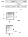
- Figure 4 illustrates the phase offset for such a method.
- This method has reduced hardware speed and bandwidth requirements when compared with merely doubling the master clock frequency of the system and synchronising the integration periods of both sensors.
- the Black Convert phase and the Image Convert phase should be equal in length
- the Reset & Image Readout and the Integration & Black Readout phases should also be of equal length so as to create a length-symmetrical frame which is required to maintain synchronism of the phase change.
- both sensors have a light intensity profile for one or more touch points that is uncorrupted by close proximity of another point or vertical or horizontal alignment of the touch points; the data for a detected touch point from each sensor can be scaled and interpolated to form a single light intensity profile for a touch point with twice the temporal resolution of the data in the frames when compared with a system with the sensors' phases running synchronously.
- Figures 5 and 6 illustrate another advantage of using such a method.
- the illumination LED paired with it will be illuminated for a time necessary to ensure that the dynamic range of the light levels received by the pixel array is as high as it can be without causing saturation of the pixels. If a sensor is not in its integration phase, the LED paired with it will not be illuminated.
- the illumination of the LEDs is mutually exclusive and therefore the light intensity gradient across the screen during the capture of a frame will be linear in a direction perpendicular to the axis upon which the integrating sensor is mounted. This linear intensity gradient 500 (shown in Figure 5 ) is easier to compensate for in image processing calculations when compared with the skewed intensity gradient 600 (shown in Figure 6 ) which would be present if both LEDs were lit simultaneously.
- touch sensitive screen is not relevant so long as it is of a type that uses the principle of sensing radiation levels in a plane parallel with a screen surface.
Landscapes
- Engineering & Computer Science (AREA)
- General Engineering & Computer Science (AREA)
- Theoretical Computer Science (AREA)
- Human Computer Interaction (AREA)
- Physics & Mathematics (AREA)
- General Physics & Mathematics (AREA)
- Position Input By Displaying (AREA)
- Length Measuring Devices By Optical Means (AREA)
Applications Claiming Priority (1)
| Application Number | Priority Date | Filing Date | Title |
|---|---|---|---|
| GBGB0921216.8A GB0921216D0 (en) | 2009-12-03 | 2009-12-03 | Improved touch screen device |
Publications (2)
| Publication Number | Publication Date |
|---|---|
| EP2339437A2 true EP2339437A2 (fr) | 2011-06-29 |
| EP2339437A3 EP2339437A3 (fr) | 2011-10-12 |
Family
ID=41641893
Family Applications (1)
| Application Number | Title | Priority Date | Filing Date |
|---|---|---|---|
| EP10193285A Withdrawn EP2339437A3 (fr) | 2009-12-03 | 2010-12-01 | Dispositif d'écran tactile amélioré |
Country Status (3)
| Country | Link |
|---|---|
| US (1) | US20110134079A1 (fr) |
| EP (1) | EP2339437A3 (fr) |
| GB (1) | GB0921216D0 (fr) |
Cited By (27)
| Publication number | Priority date | Publication date | Assignee | Title |
|---|---|---|---|---|
| WO2013055282A2 (fr) | 2011-10-11 | 2013-04-18 | Flatfrog Laboratories Ab | Détection de plusieurs entrées tactiles dans un système tactile |
| EP2706443A1 (fr) * | 2012-09-11 | 2014-03-12 | FlatFrog Laboratories AB | Estimation de force tactile dans un appareil de détection tactile de type projection selon la réflexion interne totale frustrée |
| EP2735957A1 (fr) * | 2012-11-23 | 2014-05-28 | Samsung Electronics Co., Ltd | Appareil d'affichage et son procédé de contrôle |
| US9874978B2 (en) | 2013-07-12 | 2018-01-23 | Flatfrog Laboratories Ab | Partial detect mode |
| US10019113B2 (en) | 2013-04-11 | 2018-07-10 | Flatfrog Laboratories Ab | Tomographic processing for touch detection |
| US10126882B2 (en) | 2014-01-16 | 2018-11-13 | Flatfrog Laboratories Ab | TIR-based optical touch systems of projection-type |
| US10146376B2 (en) | 2014-01-16 | 2018-12-04 | Flatfrog Laboratories Ab | Light coupling in TIR-based optical touch systems |
| US10161886B2 (en) | 2014-06-27 | 2018-12-25 | Flatfrog Laboratories Ab | Detection of surface contamination |
| US10168835B2 (en) | 2012-05-23 | 2019-01-01 | Flatfrog Laboratories Ab | Spatial resolution in touch displays |
| US10282035B2 (en) | 2016-12-07 | 2019-05-07 | Flatfrog Laboratories Ab | Touch device |
| US10318074B2 (en) | 2015-01-30 | 2019-06-11 | Flatfrog Laboratories Ab | Touch-sensing OLED display with tilted emitters |
| US10401546B2 (en) | 2015-03-02 | 2019-09-03 | Flatfrog Laboratories Ab | Optical component for light coupling |
| US10437389B2 (en) | 2017-03-28 | 2019-10-08 | Flatfrog Laboratories Ab | Touch sensing apparatus and method for assembly |
| US10474249B2 (en) | 2008-12-05 | 2019-11-12 | Flatfrog Laboratories Ab | Touch sensing apparatus and method of operating the same |
| US10481737B2 (en) | 2017-03-22 | 2019-11-19 | Flatfrog Laboratories Ab | Pen differentiation for touch display |
| US10496227B2 (en) | 2015-02-09 | 2019-12-03 | Flatfrog Laboratories Ab | Optical touch system comprising means for projecting and detecting light beams above and inside a transmissive panel |
| US10761657B2 (en) | 2016-11-24 | 2020-09-01 | Flatfrog Laboratories Ab | Automatic optimisation of touch signal |
| US11182023B2 (en) | 2015-01-28 | 2021-11-23 | Flatfrog Laboratories Ab | Dynamic touch quarantine frames |
| US11256371B2 (en) | 2017-09-01 | 2022-02-22 | Flatfrog Laboratories Ab | Optical component |
| US11301089B2 (en) | 2015-12-09 | 2022-04-12 | Flatfrog Laboratories Ab | Stylus identification |
| US11474644B2 (en) | 2017-02-06 | 2022-10-18 | Flatfrog Laboratories Ab | Optical coupling in touch-sensing systems |
| US11893189B2 (en) | 2020-02-10 | 2024-02-06 | Flatfrog Laboratories Ab | Touch-sensing apparatus |
| US11943563B2 (en) | 2019-01-25 | 2024-03-26 | FlatFrog Laboratories, AB | Videoconferencing terminal and method of operating the same |
| US12056316B2 (en) | 2019-11-25 | 2024-08-06 | Flatfrog Laboratories Ab | Touch-sensing apparatus |
| US12055969B2 (en) | 2018-10-20 | 2024-08-06 | Flatfrog Laboratories Ab | Frame for a touch-sensitive device and tool therefor |
| US12282653B2 (en) | 2020-02-08 | 2025-04-22 | Flatfrog Laboratories Ab | Touch apparatus with low latency interactions |
| US12524116B2 (en) | 2018-03-05 | 2026-01-13 | Flatfrog Laboratories Ab | Detection line broadening |
Families Citing this family (8)
| Publication number | Priority date | Publication date | Assignee | Title |
|---|---|---|---|---|
| JP5457987B2 (ja) * | 2010-09-27 | 2014-04-02 | 株式会社ジャパンディスプレイ | タッチ検出装置、タッチ検出機能付き表示装置、タッチ位置検出方法および電子機器 |
| GB201020282D0 (en) * | 2010-11-30 | 2011-01-12 | Dev Ltd | An improved input device and associated method |
| TWI456464B (zh) * | 2011-12-21 | 2014-10-11 | Pixart Imaging Inc | 光學觸控系統 |
| TWI450150B (zh) * | 2011-12-21 | 2014-08-21 | Wistron Corp | 觸控方法及觸控系統 |
| US8796566B2 (en) | 2012-02-28 | 2014-08-05 | Grayhill, Inc. | Rotary pushbutton and touchpad device and system and method for detecting rotary movement, axial displacement and touchpad gestures |
| JP5796527B2 (ja) * | 2012-03-29 | 2015-10-21 | Smk株式会社 | 静電容量式タッチパネル |
| US11782548B1 (en) * | 2020-03-25 | 2023-10-10 | Apple Inc. | Speed adapted touch detection |
| CN117076283B (zh) * | 2023-10-17 | 2024-01-26 | 江苏纳帝电子科技有限公司 | 一种触摸屏性能质量检测分析方法 |
Family Cites Families (13)
| Publication number | Priority date | Publication date | Assignee | Title |
|---|---|---|---|---|
| US5424756A (en) * | 1993-05-14 | 1995-06-13 | Ho; Yung-Lung | Track pad cursor positioning device and method |
| JP3481498B2 (ja) * | 1999-04-28 | 2003-12-22 | 日本航空電子工業株式会社 | 光学式タッチパネル |
| JP3898392B2 (ja) * | 1999-09-10 | 2007-03-28 | 株式会社リコー | 座標入力装置 |
| JP3851763B2 (ja) * | 2000-08-04 | 2006-11-29 | 株式会社シロク | 位置検出装置、位置指示器、位置検出方法及びペンダウン検出方法 |
| US6816154B2 (en) * | 2001-05-30 | 2004-11-09 | Palmone, Inc. | Optical sensor based user interface for a portable electronic device |
| US8339379B2 (en) * | 2004-04-29 | 2012-12-25 | Neonode Inc. | Light-based touch screen |
| JP2004185258A (ja) * | 2002-12-03 | 2004-07-02 | Hitachi Ltd | 情報処理装置 |
| US7432893B2 (en) * | 2003-06-14 | 2008-10-07 | Massachusetts Institute Of Technology | Input device based on frustrated total internal reflection |
| US20060001654A1 (en) * | 2004-06-30 | 2006-01-05 | National Semiconductor Corporation | Apparatus and method for performing data entry with light based touch screen displays |
| EP2137717A4 (fr) * | 2007-03-14 | 2012-01-25 | Power2B Inc | Dispositifs d'affichage et dispositifs d'entrée d'informations |
| US7973778B2 (en) * | 2007-04-16 | 2011-07-05 | Microsoft Corporation | Visual simulation of touch pressure |
| US7809221B2 (en) * | 2007-05-02 | 2010-10-05 | Poa Sana Liquidating Trust | Shadow detection in optical touch sensor through the linear combination of optical beams and grey-scale determination of detected shadow edges |
| KR101427586B1 (ko) * | 2007-12-26 | 2014-08-07 | 삼성디스플레이 주식회사 | 표시 장치 및 그 구동 방법 |
-
2009
- 2009-12-03 GB GBGB0921216.8A patent/GB0921216D0/en not_active Ceased
-
2010
- 2010-11-30 US US12/956,832 patent/US20110134079A1/en not_active Abandoned
- 2010-12-01 EP EP10193285A patent/EP2339437A3/fr not_active Withdrawn
Non-Patent Citations (1)
| Title |
|---|
| None |
Cited By (57)
| Publication number | Priority date | Publication date | Assignee | Title |
|---|---|---|---|---|
| US10474249B2 (en) | 2008-12-05 | 2019-11-12 | Flatfrog Laboratories Ab | Touch sensing apparatus and method of operating the same |
| US9377884B2 (en) | 2011-10-11 | 2016-06-28 | Flatfrog Laboratories Ab | Multi-touch detection in a touch system |
| WO2013055282A2 (fr) | 2011-10-11 | 2013-04-18 | Flatfrog Laboratories Ab | Détection de plusieurs entrées tactiles dans un système tactile |
| EP2766797A4 (fr) * | 2011-10-11 | 2015-04-29 | Flatfrog Lab Ab | Détection de plusieurs entrées tactiles dans un système tactile |
| EP3367221A1 (fr) * | 2011-10-11 | 2018-08-29 | FlatFrog Laboratories AB | Détection de plusieurs entrées tactiles dans un système tactile |
| US10168835B2 (en) | 2012-05-23 | 2019-01-01 | Flatfrog Laboratories Ab | Spatial resolution in touch displays |
| US9086763B2 (en) | 2012-09-11 | 2015-07-21 | Flatfrog Laboratories Ab | Touch force estimation in an FTIR-based projection-type touch-sensing apparatus |
| CN104662496B (zh) * | 2012-09-11 | 2017-07-07 | 平蛙实验室股份公司 | 在基于ftir的投影型触摸感测装置中的触摸力估计 |
| EP3327557A1 (fr) * | 2012-09-11 | 2018-05-30 | FlatFrog Laboratories AB | Estimation de force tactile dans un appareil de détection tactile de type projection selon la réflexion interne totale frustrée |
| CN104662496A (zh) * | 2012-09-11 | 2015-05-27 | 平蛙实验室股份公司 | 在基于ftir的投影型触摸感测装置中的触摸力估计 |
| US10088957B2 (en) | 2012-09-11 | 2018-10-02 | Flatfrog Laboratories Ab | Touch force estimation in touch-sensing apparatus |
| EP2706443A1 (fr) * | 2012-09-11 | 2014-03-12 | FlatFrog Laboratories AB | Estimation de force tactile dans un appareil de détection tactile de type projection selon la réflexion interne totale frustrée |
| WO2014042576A3 (fr) * | 2012-09-11 | 2014-05-08 | Flatfrog Laboratories Ab | Évaluation de la force d'effleurement dans un appareil d'activation par pression de type projection à base irtf |
| EP2735957A1 (fr) * | 2012-11-23 | 2014-05-28 | Samsung Electronics Co., Ltd | Appareil d'affichage et son procédé de contrôle |
| US10019113B2 (en) | 2013-04-11 | 2018-07-10 | Flatfrog Laboratories Ab | Tomographic processing for touch detection |
| US9874978B2 (en) | 2013-07-12 | 2018-01-23 | Flatfrog Laboratories Ab | Partial detect mode |
| US10146376B2 (en) | 2014-01-16 | 2018-12-04 | Flatfrog Laboratories Ab | Light coupling in TIR-based optical touch systems |
| US10126882B2 (en) | 2014-01-16 | 2018-11-13 | Flatfrog Laboratories Ab | TIR-based optical touch systems of projection-type |
| US10161886B2 (en) | 2014-06-27 | 2018-12-25 | Flatfrog Laboratories Ab | Detection of surface contamination |
| US11182023B2 (en) | 2015-01-28 | 2021-11-23 | Flatfrog Laboratories Ab | Dynamic touch quarantine frames |
| US10318074B2 (en) | 2015-01-30 | 2019-06-11 | Flatfrog Laboratories Ab | Touch-sensing OLED display with tilted emitters |
| US11029783B2 (en) | 2015-02-09 | 2021-06-08 | Flatfrog Laboratories Ab | Optical touch system comprising means for projecting and detecting light beams above and inside a transmissive panel |
| US10496227B2 (en) | 2015-02-09 | 2019-12-03 | Flatfrog Laboratories Ab | Optical touch system comprising means for projecting and detecting light beams above and inside a transmissive panel |
| US10401546B2 (en) | 2015-03-02 | 2019-09-03 | Flatfrog Laboratories Ab | Optical component for light coupling |
| US11301089B2 (en) | 2015-12-09 | 2022-04-12 | Flatfrog Laboratories Ab | Stylus identification |
| US10761657B2 (en) | 2016-11-24 | 2020-09-01 | Flatfrog Laboratories Ab | Automatic optimisation of touch signal |
| US10775935B2 (en) | 2016-12-07 | 2020-09-15 | Flatfrog Laboratories Ab | Touch device |
| US12189906B2 (en) | 2016-12-07 | 2025-01-07 | Flatfrog Laboratories Ab | Touch device |
| US10282035B2 (en) | 2016-12-07 | 2019-05-07 | Flatfrog Laboratories Ab | Touch device |
| US12566525B2 (en) | 2016-12-07 | 2026-03-03 | Flatfrog Laboratories Ab | Touch device |
| US11281335B2 (en) | 2016-12-07 | 2022-03-22 | Flatfrog Laboratories Ab | Touch device |
| US11579731B2 (en) | 2016-12-07 | 2023-02-14 | Flatfrog Laboratories Ab | Touch device |
| US11740741B2 (en) | 2017-02-06 | 2023-08-29 | Flatfrog Laboratories Ab | Optical coupling in touch-sensing systems |
| US12175044B2 (en) | 2017-02-06 | 2024-12-24 | Flatfrog Laboratories Ab | Optical coupling in touch-sensing systems |
| US11474644B2 (en) | 2017-02-06 | 2022-10-18 | Flatfrog Laboratories Ab | Optical coupling in touch-sensing systems |
| US12524117B2 (en) | 2017-02-06 | 2026-01-13 | Flatfrog Laboratories Ab | Optical coupling in touch-sensing systems |
| US11099688B2 (en) | 2017-03-22 | 2021-08-24 | Flatfrog Laboratories Ab | Eraser for touch displays |
| US10481737B2 (en) | 2017-03-22 | 2019-11-19 | Flatfrog Laboratories Ab | Pen differentiation for touch display |
| US11016605B2 (en) | 2017-03-22 | 2021-05-25 | Flatfrog Laboratories Ab | Pen differentiation for touch displays |
| US10606414B2 (en) | 2017-03-22 | 2020-03-31 | Flatfrog Laboratories Ab | Eraser for touch displays |
| US10437389B2 (en) | 2017-03-28 | 2019-10-08 | Flatfrog Laboratories Ab | Touch sensing apparatus and method for assembly |
| US11269460B2 (en) | 2017-03-28 | 2022-03-08 | Flatfrog Laboratories Ab | Touch sensing apparatus and method for assembly |
| US10606416B2 (en) | 2017-03-28 | 2020-03-31 | Flatfrog Laboratories Ab | Touch sensing apparatus and method for assembly |
| US10845923B2 (en) | 2017-03-28 | 2020-11-24 | Flatfrog Laboratories Ab | Touch sensing apparatus and method for assembly |
| US11281338B2 (en) | 2017-03-28 | 2022-03-22 | Flatfrog Laboratories Ab | Touch sensing apparatus and method for assembly |
| US10739916B2 (en) | 2017-03-28 | 2020-08-11 | Flatfrog Laboratories Ab | Touch sensing apparatus and method for assembly |
| US11256371B2 (en) | 2017-09-01 | 2022-02-22 | Flatfrog Laboratories Ab | Optical component |
| US11650699B2 (en) | 2017-09-01 | 2023-05-16 | Flatfrog Laboratories Ab | Optical component |
| US12086362B2 (en) | 2017-09-01 | 2024-09-10 | Flatfrog Laboratories Ab | Optical component |
| US12524116B2 (en) | 2018-03-05 | 2026-01-13 | Flatfrog Laboratories Ab | Detection line broadening |
| US12055969B2 (en) | 2018-10-20 | 2024-08-06 | Flatfrog Laboratories Ab | Frame for a touch-sensitive device and tool therefor |
| US11943563B2 (en) | 2019-01-25 | 2024-03-26 | FlatFrog Laboratories, AB | Videoconferencing terminal and method of operating the same |
| US12461630B2 (en) | 2019-11-25 | 2025-11-04 | Flatfrog Laboratories Ab | Touch-sensing apparatus |
| US12056316B2 (en) | 2019-11-25 | 2024-08-06 | Flatfrog Laboratories Ab | Touch-sensing apparatus |
| US12282653B2 (en) | 2020-02-08 | 2025-04-22 | Flatfrog Laboratories Ab | Touch apparatus with low latency interactions |
| US11893189B2 (en) | 2020-02-10 | 2024-02-06 | Flatfrog Laboratories Ab | Touch-sensing apparatus |
| US12704928B2 (en) | 2020-02-10 | 2026-08-11 | Flatfrog Laboratories Ab | Touch-sensing apparatus |
Also Published As
| Publication number | Publication date |
|---|---|
| EP2339437A3 (fr) | 2011-10-12 |
| GB0921216D0 (en) | 2010-01-20 |
| US20110134079A1 (en) | 2011-06-09 |
Similar Documents
| Publication | Publication Date | Title |
|---|---|---|
| US20110134079A1 (en) | Touch screen device | |
| US8600107B2 (en) | Interactive input system and method | |
| US20160357260A1 (en) | Distance independent gesture detection | |
| EP3087341B1 (fr) | Procédé pour reconstruire une surface utilisant une lumière structurée spatialement et un capteur de vision dynamique | |
| EP2353069B1 (fr) | Capteurs optiques stéréos pour résoudre un toucher multiple dans un système de détection de toucher | |
| EP2325625A1 (fr) | Système d'inspection | |
| US8937612B2 (en) | Coordinate locating method, coordinate locating device, and display apparatus comprising the coordinate locating device | |
| US8659577B2 (en) | Touch system and pointer coordinate detection method therefor | |
| KR101238748B1 (ko) | 주사구동 적외선센서장치를 이용한 표적거리 측정시스템 | |
| EP2790093B1 (fr) | Procédé pour détection de geste, circuit à capteur optique, en particulier un circuit de capteur optique pour une détection de geste et dispositif de capteur optique pour la détection de geste | |
| US9341470B2 (en) | Light section sensor | |
| TWI442289B (zh) | 位移偵測裝置及其操作方法 | |
| TW201140400A (en) | Scanning method for determining the touch position of touch input apparatus | |
| US20130057516A1 (en) | Optical touch-control system with track detecting function and method thereof | |
| KR20150046238A (ko) | 적외선 광 소스의 움직임을 검출하기 위한 센서 시스템 | |
| US8780084B2 (en) | Apparatus for detecting a touching position on a flat panel display and a method thereof | |
| JP5554689B2 (ja) | 位置および動作判定方法および入力装置 | |
| JP7148126B2 (ja) | 移動体検知システム及び移動体検知システム用プログラム | |
| GB2523077A (en) | Touch sensing systems | |
| CN103076925B (zh) | 光学触控系统、光学感测模块及其运作方法 | |
| US20190293419A1 (en) | Distance detection device | |
| TW201317858A (zh) | 光學觸控系統、光學感測模組及其運作方法 | |
| CN102314263B (zh) | 光学触控屏幕系统、光学距离判断装置及其方法 | |
| TW201007520A (en) | 3-dimensional interactive display and method for detecting 3-dimensional coordinates thereof | |
| TWI528247B (zh) | 觸控點感測方法及光學觸控系統 |
Legal Events
| Date | Code | Title | Description |
|---|---|---|---|
| PUAI | Public reference made under article 153(3) epc to a published international application that has entered the european phase |
Free format text: ORIGINAL CODE: 0009012 |
|
| AK | Designated contracting states |
Kind code of ref document: A2 Designated state(s): AL AT BE BG CH CY CZ DE DK EE ES FI FR GB GR HR HU IE IS IT LI LT LU LV MC MK MT NL NO PL PT RO RS SE SI SK SM TR |
|
| AX | Request for extension of the european patent |
Extension state: BA ME |
|
| PUAL | Search report despatched |
Free format text: ORIGINAL CODE: 0009013 |
|
| AK | Designated contracting states |
Kind code of ref document: A3 Designated state(s): AL AT BE BG CH CY CZ DE DK EE ES FI FR GB GR HR HU IE IS IT LI LT LU LV MC MK MT NL NO PL PT RO RS SE SI SK SM TR |
|
| AX | Request for extension of the european patent |
Extension state: BA ME |
|
| RIC1 | Information provided on ipc code assigned before grant |
Ipc: G06F 3/041 20060101ALI20110907BHEP Ipc: G06F 3/048 20060101ALI20110907BHEP Ipc: G06F 3/042 20060101AFI20110907BHEP |
|
| 17P | Request for examination filed |
Effective date: 20120328 |
|
| STAA | Information on the status of an ep patent application or granted ep patent |
Free format text: STATUS: THE APPLICATION IS DEEMED TO BE WITHDRAWN |
|
| 18D | Application deemed to be withdrawn |
Effective date: 20150701 |