EP2339487A2 - Verfahren und system zum anpassen einer mehrblöckigen strukturierten vermaschung eines objekts an eine modifikation seiner geometrie - Google Patents
Verfahren und system zum anpassen einer mehrblöckigen strukturierten vermaschung eines objekts an eine modifikation seiner geometrie Download PDFInfo
- Publication number
- EP2339487A2 EP2339487A2 EP09740710A EP09740710A EP2339487A2 EP 2339487 A2 EP2339487 A2 EP 2339487A2 EP 09740710 A EP09740710 A EP 09740710A EP 09740710 A EP09740710 A EP 09740710A EP 2339487 A2 EP2339487 A2 EP 2339487A2
- Authority
- EP
- European Patent Office
- Prior art keywords
- vertexes
- geometry
- key
- htp
- starting
- Prior art date
- Legal status (The legal status is an assumption and is not a legal conclusion. Google has not performed a legal analysis and makes no representation as to the accuracy of the status listed.)
- Withdrawn
Links
Images

Classifications
-
- G—PHYSICS
- G06—COMPUTING OR CALCULATING; COUNTING
- G06F—ELECTRIC DIGITAL DATA PROCESSING
- G06F30/00—Computer-aided design [CAD]
- G06F30/10—Geometric CAD
- G06F30/15—Vehicle, aircraft or watercraft design
-
- G—PHYSICS
- G06—COMPUTING OR CALCULATING; COUNTING
- G06F—ELECTRIC DIGITAL DATA PROCESSING
- G06F30/00—Computer-aided design [CAD]
- G06F30/20—Design optimisation, verification or simulation
- G06F30/23—Design optimisation, verification or simulation using finite element methods [FEM] or finite difference methods [FDM]
-
- G—PHYSICS
- G06—COMPUTING OR CALCULATING; COUNTING
- G06T—IMAGE DATA PROCESSING OR GENERATION, IN GENERAL
- G06T17/00—Three-dimensional [3D] modelling for computer graphics
- G06T17/20—Finite element generation, e.g. wire-frame surface description, tesselation
-
- G—PHYSICS
- G06—COMPUTING OR CALCULATING; COUNTING
- G06F—ELECTRIC DIGITAL DATA PROCESSING
- G06F2111/00—Details relating to CAD techniques
- G06F2111/10—Numerical modelling
Definitions
- the present invention refers to methods and systems for adapting a multi-block structured mesh topology of an object to a modification in its geometry, particularly in the aeronautical field.
- CFD discretizes the physical domain into small cells where the Navier-Stokes equations or simplifications of them, for example the Reynolds Averaged Navier-Stokes, are computed. That implies that in order to perform a good computation one needs a good mesh.
- the meshes used in design activities using numerical simulation tools such as CFD are of three types: entirely structured, totally unstructured or hybrid, that is a mixture of these two mesh types.
- Structured meshes are meshes whose connectivity is regular and fixed by the topology: each inner vertex is topologically connected to his neighbours inside the block. Also the number of cells are propagated inside the block and to the neighbour blocks. All nodes inside a structured mesh can be located using indexes (l,j,k), so that connectivity is explicit.
- Unstructured meshes have a completely arbitrary connectivity: a vertex of the mesh can belong to any number of cells and each cell can have any number of edges or sides. The topological data therefore have to be permanently stored to explicitly know the neighbours of each node. The memory cost involved by the use of an unstructured mesh can therefore become very rapidly penalizing.
- structured meshes are divided in several blocks, creating multiblock-structured-meshes in which the actual geometry is formed by several structured blocks, having structurally ordered meshes inside them.
- Topology is the arrangement in which the blocks and vertexes of a mesh are connected to each other. Vertexes are linked to each other by edges. Vertexes and edges form the multi-block structure. The structured mesh is finally calculated for each block.
- some topologies related to aircrafts are a body-tails topology, a wing-body-tails topology, or a T-tail topology.
- these and other objects are met by providing a computer-aided method for adapting a multi-block mesh topology of an object to a modification in its geometry resulting from an operation defined in respect to one or more spatial directions, the method being used in the design of said object by means of numerical simulation in entirely or partially structured meshes, comprising the following steps:
- the step of finding the key points is carried out using a data base containing the set of needed key points and the way to find them for a set of standard geometry types (e.g. conventional tail aircraft or a T-tail aircraft).
- a data base containing the set of needed key points and the way to find them for a set of standard geometry types (e.g. conventional tail aircraft or a T-tail aircraft).
- the above-mentioned objects are met by providing a system for adapting a multi-block structured mesh topology of an object to a modification in its geometry resulting from an operation defined in respect to one or more directions, the system being used in the design of said object by means of numerical simulation in entirely or partially structured meshes, comprising:
- the method comprises the following steps:
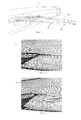
- the input consist in a starting geometry 21 of the horizontal tail plane 11 (see Figure 1 ) and in a topology description of the corresponding starting mesh 31 (see Figure 2 ).
- the starting geometry 21 can be provided in a CAD format.
- the topology of the starting mesh 31 (generated following any known procedure) is provided using a given naming criteria for identifying all geometrical entities (curves, surfaces and materials).
- a set of key points is identified. These are the geometrical points that will be taken as a reference to start searching for all the reference vertexes. They should be univocal and representative of the geometry. Their positions will represent the origin from which to start searching for all the vertexes needed for the mesh topology adaptation, so they will be generally placed in geometrical extremes of the object (e.g. the wingtip of an aircraft or the prow of a boat).
- the identification of each key point is done as the intersection of the corresponding geometrical entities.
- the key points to be identified depend on the object being designed, taking into account that the object or its parts should be oriented along preferential directions.
- the identification of the key points is made using a data base containing the set of needed key points and the way to find them (curve-curve or curve-surface intersection), for a set of standard geometry types.
- This data base ensures the use of the same set of key points for a given geometry, contributing to the method standardization.
- the key point 25 (see figure 4 ) will be identified as the intersection of the HTP leading edge 27 and the HTP trailing edge middle line 29.
- vertexes are geometrical entities defined by their three coordinates
- vertexes are topological entities. Vertexes are defined by their coordinates and connectivity (the way in which ones are connected to others by edges).
- the coordinates of each vertex are retrieved. After that, the distances from each vertex to each key point are calculated and the nearest vertex to each key point (the key vertexes of the blocking structure) are identified.
- the reference vertexes involved in the modification of the geometry of the object are found which is, usually, the result of operations such as rotations or translations applied to the base geometry, for example, in the case of the horizontal tail plane 11 that it is being considered in this description, the result of applying a rotation of 5 degrees for obtaining the rotated geometry 23 shown in Figure 1 .
- This step is carried out using a procedure that seeks for new vertexes along any desired direction in order to find all the vertexes needed for the operation.
- each searching step we can consider X, Y, Z directions, or any other direction given by a vector.
- the point represented by each key vertex is also known (e.g. a wingtip) the set of vertexes that should be founded while advancing in a particular direction is also known (e.g. from a wingtip key vertex, while advancing in -Y direction, the leading edge vertexes should be founded).
- an approximate direction this is, the path, formed by connecting edges, that better follows the desired direction.
- the direction or directions to be followed from each key vertex may be also incorporated to the above-mentioned data base in order to avoid user decisions.
- This procedure checks the connectivity of each vertex (identifies the edge that connects it with its neighbours), and calculates the normalized vector that defines the direction of each one.
- the angle formed by each of the edges with each direction (also defined as a normalized vector) is calculated and therefore we can identify a set of vertexes by advancing in the desired direction.
- Moving blocks implies moving all projected vertexes and edges. After performing the block rotation, it is necessary to rearrange the position of the nearby topology so that the mesh doesn't suffer big deformations in those zones.
- the algorithms used for this will take into account the vertexes projected on the rotated parts (that have already been moved as needed) and the ones projected on some fixed reference curve or surface (that should be kept in their place). Then, by searching along the direction that goes from one part to another, the volumetric vertexes that are in-between are identified, and moved in an amount that is inversely proportional to their distance to the moving part.
- d 1
- d 2
- the displacement vector of vertex P j is given by: u ⁇ ⁇ 1 - d j d n ⁇ P j ⁇ P j + 1 ⁇ P j ⁇ P j + 1 ⁇
- the key vertexes (always projected vertexes) will be moved to the new positions (e.g. in an aircraft, tip HTP vertex to the new intersection of HTP leading and trailing edges) while volume vertexes will be displaced in certain distances and directions, calculated with the same algorithm described for the rotation case. This process is performed over all the vertexes that have been identified as projected over a particular curve or surface, while keeping this projection, and then over the rest of the reference vertexes (volume vertexes).
- HTP Horizontal Tail Plane
- the following data are defined in a text input file: names of the reference tetin (geometry) and blocking (topology) files, names of the output files to be written, the naming convention to be used, so that the program will identify all geometrical entities (curves, surfaces and materials), the operation to be performed (HTP rotation), the direction of the rotating axis, and a point of this axis.
- Fuselage rear end upper point at the symmetry plane K10: as intersection of fuselage-symmetry plane curve (C_GEOMETRIC/C_FUS) and fuselage rear end curve (C_GEOMETRIC/C_FUS_TTE). From the two points obtained, the one with higher Z coordinate should be taken.
- Fuselage rear end lower point at the symmetry plane K11: as intersection of fuselage-symmetry plane curve (C_GEOMETRIC/C_FUS) and fuselage rear end curve (C_GEOMETRIC/C_FUS_TTE). From the two points obtained, the one with lower Z coordinate should be taken.
- the original blocking file is automatically loaded and the corresponding key vertexes are identified.
- HTP leading edge vertexes (P1) from K2 to K1 along +Y direction.
- HTP trailing edge lower line vertexes (P4) from K5 to K1 along +Y direction.
- HTP surface vertexes (P5) from each vertex of set P1 to the corresponding vertex in set P3, a P5 subset is created by advancing in +X direction. In the same way, subsets will be created by advancing from vertexes in set P1 to vertexes in set P4.
- HTP surrounding vertexes from each vertex in set P5, a P7 subset is created by advancing three steps +Z or -Z direction, depending on the position of the reference vertex (upper or lower side of the HTP). Special care is taken, by searching in directions defined by a vector, when the origin of the search corresponds to the vertexes over the HTP-fuselage intersection curve, to assure that the vertexes are founded over the fuselage surface, so those vertexes between HTP and VTP and between HTP and symmetry plane are correctly identified.
- HTP wake vertexes P8. Taking as reference all vertexes from sets P2, P3 and P4, a P8 subset is created by advancing three steps in +Z direction.
- Blocks are volumetric topological entities enclosed by edges.
- the blocking is adapted to the rotated geometry, but blocks surrounding the HTP are deformed, giving a poor mesh quality.
- Figure 2 illustrates the base mesh 31 and the modified mesh 33 after completing the rotation (only a zone around the HTP leading edge intersection is shown).
- the methods and systems according to this invention are particularly applicable to the design or analysis of airplanes or any of its parts.
Landscapes
- Engineering & Computer Science (AREA)
- Physics & Mathematics (AREA)
- Theoretical Computer Science (AREA)
- Geometry (AREA)
- General Physics & Mathematics (AREA)
- Computer Hardware Design (AREA)
- Evolutionary Computation (AREA)
- General Engineering & Computer Science (AREA)
- Computer Graphics (AREA)
- Software Systems (AREA)
- Automation & Control Theory (AREA)
- Aviation & Aerospace Engineering (AREA)
- Computational Mathematics (AREA)
- Mathematical Analysis (AREA)
- Mathematical Optimization (AREA)
- Pure & Applied Mathematics (AREA)
- Processing Or Creating Images (AREA)
Applications Claiming Priority (2)
| Application Number | Priority Date | Filing Date | Title |
|---|---|---|---|
| ES200802545A ES2351411B1 (es) | 2008-09-03 | 2008-09-03 | Métodos y sistemas para adaptar la topología de una malla estructurada multi-bloque de un objeto a una modificación de su geometría. |
| PCT/ES2009/070363 WO2010026273A2 (es) | 2008-09-03 | 2009-09-03 | Metodos y sistemas para adaptar la topología de una malla estructurada multi-bloque de un objeto a una modificacion de su geometría. |
Publications (1)
| Publication Number | Publication Date |
|---|---|
| EP2339487A2 true EP2339487A2 (de) | 2011-06-29 |
Family
ID=41724676
Family Applications (1)
| Application Number | Title | Priority Date | Filing Date |
|---|---|---|---|
| EP09740710A Withdrawn EP2339487A2 (de) | 2008-09-03 | 2009-09-03 | Verfahren und system zum anpassen einer mehrblöckigen strukturierten vermaschung eines objekts an eine modifikation seiner geometrie |
Country Status (5)
| Country | Link |
|---|---|
| US (1) | US20100053170A1 (de) |
| EP (1) | EP2339487A2 (de) |
| CA (1) | CA2739398A1 (de) |
| ES (1) | ES2351411B1 (de) |
| WO (1) | WO2010026273A2 (de) |
Cited By (3)
| Publication number | Priority date | Publication date | Assignee | Title |
|---|---|---|---|---|
| CN103164586A (zh) * | 2013-04-10 | 2013-06-19 | 中国矿业大学 | 基于组件的矿井巷道整体拼接算法 |
| CN105302927A (zh) * | 2014-05-28 | 2016-02-03 | 杭州恒达钢构股份有限公司 | 一种任意曲面建立空间网格结构的方法 |
| CN107016218A (zh) * | 2017-05-02 | 2017-08-04 | 西安合科软件有限公司 | 一种确定飞机翼尖小翼翼面中有限元点载荷分布的方法与装置 |
Families Citing this family (7)
| Publication number | Priority date | Publication date | Assignee | Title |
|---|---|---|---|---|
| US10956625B2 (en) | 2015-09-01 | 2021-03-23 | Siemens Industry Software Inc. | Mesh generation system and method |
| GB201617666D0 (en) * | 2016-10-19 | 2016-11-30 | Rolls Royce Plc | Optimization of an automatically meshable shapes |
| US11416647B2 (en) | 2018-04-24 | 2022-08-16 | Honeywell Federal Manufacturing & Technologies, Llc | Computer-aided design file format for additive manufacturing and methods of file generation |
| US11416648B2 (en) | 2018-04-24 | 2022-08-16 | Honeywell Federal Manufacturing & Technologies, Llc | Computer-aided design file format for additive manufacturing and methods of file generation |
| CN112685935B (zh) * | 2020-12-25 | 2024-03-15 | 中国航空发动机研究院 | 一种二维多块结构化网格拓扑划分方法 |
| CN116011049B (zh) * | 2023-03-27 | 2023-07-07 | 北京科技大学 | 一种结构化网格过渡拓扑结构的参数化生成方法及装置 |
| CN117272500B (zh) * | 2023-07-24 | 2024-10-15 | 四川大学 | 一种基于多块拓扑的旋转机械结构网格自动生成方法 |
Family Cites Families (13)
| Publication number | Priority date | Publication date | Assignee | Title |
|---|---|---|---|---|
| US5923329A (en) * | 1996-06-24 | 1999-07-13 | National Research Council Of Canada | Method of grid generation about or within a 3 dimensional object |
| AU3718497A (en) * | 1996-06-28 | 1998-01-21 | Resolution Technologies, Inc. | Fly-through computer aided design method and apparatus |
| WO1999034336A1 (en) * | 1997-12-29 | 1999-07-08 | The United States Of America, Represented By The Administrator Of The National Aeronautics And Space Administration (Nasa) | Triangle geometry processing for surface modeling and cartesian grid generation |
| US6879324B1 (en) * | 1998-07-14 | 2005-04-12 | Microsoft Corporation | Regional progressive meshes |
| US6895371B1 (en) * | 2000-09-11 | 2005-05-17 | The United States Of America As Represented By The Secretary Of The Navy | Geometrical modeling of structural products |
| US7324103B2 (en) * | 2001-10-30 | 2008-01-29 | Ford Motor Company | System and method of direct mesh manipulation |
| JP3621378B2 (ja) * | 2001-12-28 | 2005-02-16 | 川崎重工業株式会社 | 格子収束解の算出システム |
| US7812815B2 (en) * | 2005-01-25 | 2010-10-12 | The Broad of Trustees of the University of Illinois | Compact haptic and augmented virtual reality system |
| EP1901235B1 (de) * | 2006-09-15 | 2019-08-14 | Honda Research Institute Europe GmbH | Freistildeformation (FSD) |
| US20080275677A1 (en) * | 2007-03-19 | 2008-11-06 | Optimal Solutions Software, Llc | System, methods, and computer readable media, for product design using coupled computer aided engineering models |
| CA2631043C (en) * | 2007-05-10 | 2016-08-09 | Simon Fraser University | Systems and methods for implementing haptic systems and simulated environments |
| US8111256B2 (en) * | 2008-03-11 | 2012-02-07 | Ford Motor Company | Method of altering a mesh model using model independent dirichlet parametrization |
| WO2010042731A2 (en) * | 2008-10-10 | 2010-04-15 | The University Of Utah Research Foundation | Mesh formation for multi-element volumes |
-
2008
- 2008-09-03 ES ES200802545A patent/ES2351411B1/es not_active Expired - Fee Related
- 2008-11-03 US US12/263,534 patent/US20100053170A1/en not_active Abandoned
-
2009
- 2009-09-03 EP EP09740710A patent/EP2339487A2/de not_active Withdrawn
- 2009-09-03 WO PCT/ES2009/070363 patent/WO2010026273A2/es not_active Ceased
- 2009-09-03 CA CA2739398A patent/CA2739398A1/en not_active Abandoned
Non-Patent Citations (2)
| Title |
|---|
| None * |
| See also references of WO2010026273A2 * |
Cited By (4)
| Publication number | Priority date | Publication date | Assignee | Title |
|---|---|---|---|---|
| CN103164586A (zh) * | 2013-04-10 | 2013-06-19 | 中国矿业大学 | 基于组件的矿井巷道整体拼接算法 |
| CN103164586B (zh) * | 2013-04-10 | 2015-11-04 | 中国矿业大学 | 基于组件的矿井巷道整体拼接方法 |
| CN105302927A (zh) * | 2014-05-28 | 2016-02-03 | 杭州恒达钢构股份有限公司 | 一种任意曲面建立空间网格结构的方法 |
| CN107016218A (zh) * | 2017-05-02 | 2017-08-04 | 西安合科软件有限公司 | 一种确定飞机翼尖小翼翼面中有限元点载荷分布的方法与装置 |
Also Published As
| Publication number | Publication date |
|---|---|
| CA2739398A1 (en) | 2010-03-11 |
| WO2010026273A2 (es) | 2010-03-11 |
| US20100053170A1 (en) | 2010-03-04 |
| ES2351411B1 (es) | 2011-12-16 |
| ES2351411A1 (es) | 2011-02-04 |
| WO2010026273A3 (es) | 2010-08-12 |
Similar Documents
| Publication | Publication Date | Title |
|---|---|---|
| US20100053170A1 (en) | Methods and systems for adapting a multi-block structured mesh topology of an object to a modification in its geometry | |
| US8831913B2 (en) | Method of design optimisation | |
| Li et al. | Surrogate-based aerodynamic shape optimization with the active subspace method | |
| Biancolini et al. | Glider fuselage-wing junction optimization using CFD and RBF mesh morphing | |
| US20030080957A1 (en) | System and method of direct mesh manipulation | |
| Xu et al. | Wing-body junction optimisation with CAD-based parametrisation including a moving intersection | |
| Petsch et al. | PANDORA-A python based framework for modelling and structural sizing of transport aircraft | |
| CN115952705A (zh) | 设计建模对象 | |
| Park et al. | Boundary representation tolerance impacts on mesh generation and adaptation | |
| Morris et al. | Parametric geometry model for design studies of tailless supersonic aircraft | |
| Sun et al. | Automated mesh deformation for computer-aided design models that exhibit boundary topology changes | |
| Núñez et al. | Implementation of immersed boundaries via volume penalization in the industrial aeronautical computational fluid dynamics solver CODA | |
| US20250148169A1 (en) | Mirror Finite Element Mesh Generation | |
| Dubovikov | Novel approach and algorithm for searching rational nonconventional airframe concepts of new generation aircrafts | |
| Hall et al. | Volumetric shape parameterisation for combined aerodynamic geometry and topology optimisation | |
| Sclafani et al. | CFL3D/OVERFLOW results for DLR-F6 wing/body and drag prediction workshop wing | |
| Pustina et al. | NERONE: An Open-Source Based Tool for Aerodynamic Transonic Optimization of Nonplanar Wings: L. Pustina et al. | |
| Sensmeier et al. | Rapid generation and assessment of aircraft structural topologies for multidisciplinary optimization and weight estimation | |
| Dattoma et al. | A parametric–associative modelling of aeronautical concepts for structural optimisation | |
| CN110415350A (zh) | 一种管道运输工具气动模型构建方法及系统 | |
| Ronzheimer | Aircraft geometry parameterization with high-end CAD-software for design optimization | |
| Chen et al. | A real-time, interactive method for fast modification of large-scale CAE mesh models | |
| Wang et al. | A novel approach for large-scale hybrid mesh generation on distributed systems | |
| JP2009276147A (ja) | フィラー充填ゴムの解析モデルの作成方法 | |
| Papakonstantinou | Investigation on meshing techniques for the CFD modelling of rotating wheels in cars |
Legal Events
| Date | Code | Title | Description |
|---|---|---|---|
| PUAI | Public reference made under article 153(3) epc to a published international application that has entered the european phase |
Free format text: ORIGINAL CODE: 0009012 |
|
| 17P | Request for examination filed |
Effective date: 20110330 |
|
| AK | Designated contracting states |
Kind code of ref document: A2 Designated state(s): AT BE BG CH CY CZ DE DK EE ES FI FR GB GR HR HU IE IS IT LI LT LU LV MC MK MT NL NO PL PT RO SE SI SK SM TR |
|
| AX | Request for extension of the european patent |
Extension state: AL BA RS |
|
| DAX | Request for extension of the european patent (deleted) | ||
| RIN1 | Information on inventor provided before grant (corrected) |
Inventor name: PERDONES DIAZ, DAVID Inventor name: ESQUEJ ALONSO, ROBERTO Inventor name: DE PABLO FOUCE, VALENTIN Inventor name: OSSORIO CONTRERAS, VICTOR Inventor name: DEL CAMPO SUD, DAVID |
|
| 17Q | First examination report despatched |
Effective date: 20170412 |
|
| STAA | Information on the status of an ep patent application or granted ep patent |
Free format text: STATUS: THE APPLICATION IS DEEMED TO BE WITHDRAWN |
|
| 18D | Application deemed to be withdrawn |
Effective date: 20171024 |