EP2339718A2 - Aimant pivotant - Google Patents
Aimant pivotant Download PDFInfo
- Publication number
- EP2339718A2 EP2339718A2 EP10015712A EP10015712A EP2339718A2 EP 2339718 A2 EP2339718 A2 EP 2339718A2 EP 10015712 A EP10015712 A EP 10015712A EP 10015712 A EP10015712 A EP 10015712A EP 2339718 A2 EP2339718 A2 EP 2339718A2
- Authority
- EP
- European Patent Office
- Prior art keywords
- pole
- coil
- rotor
- stator
- rotary magnet
- Prior art date
- Legal status (The legal status is an assumption and is not a legal conclusion. Google has not performed a legal analysis and makes no representation as to the accuracy of the status listed.)
- Withdrawn
Links
Images
Classifications
-
- H—ELECTRICITY
- H02—GENERATION; CONVERSION OR DISTRIBUTION OF ELECTRIC POWER
- H02K—DYNAMO-ELECTRIC MACHINES
- H02K26/00—Machines adapted to function as torque motors, i.e. to exert a torque when stalled
-
- H—ELECTRICITY
- H02—GENERATION; CONVERSION OR DISTRIBUTION OF ELECTRIC POWER
- H02K—DYNAMO-ELECTRIC MACHINES
- H02K37/00—Motors with rotor rotating step by step and without interrupter or commutator driven by the rotor, e.g. stepping motors
- H02K37/10—Motors with rotor rotating step by step and without interrupter or commutator driven by the rotor, e.g. stepping motors of permanent magnet type
- H02K37/12—Motors with rotor rotating step by step and without interrupter or commutator driven by the rotor, e.g. stepping motors of permanent magnet type with stationary armatures and rotating magnets
- H02K37/125—Magnet axially facing armature
-
- H—ELECTRICITY
- H01—ELECTRIC ELEMENTS
- H01F—MAGNETS; INDUCTANCES; TRANSFORMERS; SELECTION OF MATERIALS FOR THEIR MAGNETIC PROPERTIES
- H01F7/00—Magnets
- H01F7/06—Electromagnets; Actuators including electromagnets
- H01F7/08—Electromagnets; Actuators including electromagnets with armatures
-
- H—ELECTRICITY
- H02—GENERATION; CONVERSION OR DISTRIBUTION OF ELECTRIC POWER
- H02K—DYNAMO-ELECTRIC MACHINES
- H02K37/00—Motors with rotor rotating step by step and without interrupter or commutator driven by the rotor, e.g. stepping motors
- H02K37/10—Motors with rotor rotating step by step and without interrupter or commutator driven by the rotor, e.g. stepping motors of permanent magnet type
Definitions
- the invention relates to a rotary magnet, comprising a stator and a rotatable about a rotation axis rotor, wherein the rotor has a rotor shaft on which a rotor disk is arranged and the rotor disk seen in the circumferential direction, alternating, magnetically polarized and the stator at least one, windings electrically conductive wire carrying coil receives and provided between the coil and the rotor disk a preferably arranged at right angles to the axis of rotation pole surface.
- the generic rotary magnets are based on the electromagnetic principle drives in which instead of a Longitudinal or longitudinal motion results in a rotational movement.
- Generic rotary solenoids are known, for example, as rotationally proportional solenoids which, due to the current flow through the windings, perform a rotational movement proportional to the current flow.
- the invention is based on a rotary magnet as described above and proposes that the pole face at least two of the magnetic flux guide of the magnetic field generated by the application of current to the winding of the coil serving pole faces exists, whereby at the pole face a, based on the Rotary axis seen in the circumferential direction, alternating, magnetic polarization exists. Furthermore, the invention proposes that the windings of the coil enclose the axis of rotation.
- the proposal of the invention achieves that standard coils can be used in rotary actuators according to the invention.
- the use of standard coils is favorable in two respects, since on the one hand the winding technique on cylindrical bobbins is well known and no other special manufacturing processes are necessary, the production is therefore favorable.
- the arrangement of the coil is such that the windings enclose the axis of rotation, that is, the axis of rotation extends within the coil.
- the rotor disk is magnetically acted upon accordingly, for example, the rotor disk itself consists of a permanent magnetic material or carries a corresponding coating with a corresponding alternating polarization or on the rotor disk, an additional ring or ring of permanent magnets is arranged in the desired shape, the rotor disk then For example, consists of a ferromagnetic material.
- the proposal according to the invention comprises all these solutions.
- a Polspalt is provided, which extends in the radial direction relative to the axis of rotation.
- the pole face which is bordered by a Polspalt edge, it is possible to control the rotationally or point-symmetrical magnetic field line distribution, which normally results in a current flowing coil, so that a deviating from the rotational or point symmetry magnetic field line results .
- the invention exploits the property that a heterogeneous distribution of the magnetic field lines takes place through the corresponding arrangement of the magnetic field lines leading soft magnetic material (for example, corresponding iron alloy and the like).
- the pole gap which results between the two pole faces e.g. is filled under a magnetically less effective or ineffective material or the pole gap is designed as a fresh air gap.
- the resulting pole gap is filled or open.
- the backfilling material used e.g. a polymer or the like, serves to connect the pole faces dense with each other in order to suppress a magnetic field line flow as possible, for this purpose to be as insulating as possible.
- the arrangement of the different pole faces is realized so that seen in the circumferential direction (relative to the axis of rotation) an alternating, magnetic polarization exists.
- an arrangement is chosen, for example, in a variant according to the invention, which of course can be implemented in conjunction with all the above and below described embodiments as well as combinations of these embodiments, in which a first outer pole part surface encloses a second, inner pole part surface.
- the first, outer Polteil configuration example, part of a larger component, in which then the second, inner Polteil arrangements is used in a suitable manner, skillfully remaining between these two Polteil vom a Polspalt.
- an axisymmetric configuration of the pole part surface is used.
- at least one or a few axes of symmetry in the design of the pole piece surface provided in order to achieve a corresponding similar behavior of the rotary magnet (regardless of its position).
- the pole face according to the invention is divided into at least two pole faces.
- these two pole faces are coplanar with each other, that is, points of both the first and the second or all Polteil vom lie on a common plane.
- the surface facing the rotor disk is regarded as the pole part surface. Due to the orthogonal arrangement of the pole face and thus also the pole faces with respect to the axis of rotation, follows an independent of the position of the rotor of the same size air gap between the rotor disc and the pole face.
- the second, in particular inner Polteil configuration seen in plan view formed longitudinally. It is implemented rectangular, with corresponding (radially extending) expansions may be provided on the longitudinal sides in the end region.
- the ratio of the length to the width of this Polteil configuration is about 2: 1, it can according to the invention in an interval of 1.5: 1 to 4: 1. It is clear that the magnetic property of the rotary magnet is adjustable by the configuration of the inner as well as the outer pole part surface.
- the invention comprises variants of the Polteil configuration, which has both a two-part symmetry (symmetrical only with respect to two symmetry axes), as well as solutions which have a four-, six- or eight-part (or higher part) symmetry.
- the correspondingly more complex pole faces resulting therefrom then possibly become more similar to a round outer contour.
- the pole face is for example along its longitudinal axis and the perpendicular transverse axis designed symmetrsich.
- the stator is in a variant according to the invention, which of course can be realized with all embodiments of the invention described above and below and combinations thereof, designed so that it surrounds the coil or surrounds and serves as a housing. Since the coil is configured rotationally symmetrical, in particular cylindrical, the stator also has a prizipell cylindrical or pot-like design. The arrangement is optionally chosen so that the stator rests on the outside and / or inside of the coil for guiding purposes. In particular, in a variant according to the invention, it is provided that the stator has a center pole penetrating the coil and carrying the second inner pole part surface, in particular a spike-like center pole. The arrangement is chosen so that the center of gravity of the second, inner Polteil designs comes to rest on the axis of rotation. This results in the most accurate, centric arrangement of the inner, second Polteil constitutional.
- the stator of the magnetic flux guide serves the magnetic field generated by the current applied to the winding of the coil and is preferably made of soft magnetic iron.
- soft magnetic iron instead of the soft magnetic iron according to the invention, all other materials can be used which optimally serve to guide the magnetic flux.
- the stator is pot-shaped with a centrally or coaxially arranged center pole. Just but the outer area surrounding the coil is now cleverly used to guide the magnetic field, thereby significantly increasing the efficiency of the entire array. Since such an arrangement is unknown in the prior art, a surprising advantage is achieved by this measure, in which the stator is now assigned not only the fixed task of a rotating arrangement, but this also additionally the task of guiding the magnetic field as well as a Housing task takes over.
- the stator is designed in several parts and at least one shell part receives the coil and a cover part connects to the shell part and this closes. Due to the multi-part construction, it is possible to use the coil in a first part, the shell part, and to close this by a second part, the cover part. For example, the two parts are pressed together or caulked and so for optimal magnetic flow, connected together. In addition to these mechanical connection methods, of course, other connection methods can also be used according to the invention; this includes, for example, joining with the aid of a screw connection or welding, gluing or soldering. In addition to the two-part design of the stator described here, it is of course also possible to realize the stator from even more components, for example three or more components. A multi-part design may have particular manufacturing reasons and benefits.
- the arrangement is chosen such that the stator forms a pole piece surface, this (first, outer) pole piece surface being arranged in particular in or on the lid part.
- provision is made for the stator, in particular the cover part, to have a recess for receiving the second pole face in the area of the first pole face, and the contour of the recess to correspond to the contour of the second pole face, at least partially extending between a pole pole gap between the two pole faces.
- the invention in all embodiments and combinations thereof also includes that the stator also receives a plurality of pole faces in a suitable manner.
- the invention also extends in particular to variants which consist of three, four or even more individual pole faces.
- a Polteil Structure with the stator or a part of the stator may be integrally formed.
- the attachment opening is arranged, for example, in a flange-like projection.
- the rotor disk carries on its side facing the coil at least one ring of permanent magnets.
- This ring of permanent magnets consists of a larger number of respect to their dimension as well as their remaining magnetization like permanent magnet.
- the individual permanent magnets are arranged to a ring (with a constant radius), the center of which lies on the axis of rotation, whereby preferably results in an arrangement of individual ring sectors with the same length. If the individual permanent magnets also have the same magnetization, the course of the magnetic field lines in the At least approximately the same for each sector.
- the arrangement is chosen such that an alternating polarization results, ie in the circumferential direction (relative to the axis of rotation of the rotor disk) results in an alternating magnetic pole arrangement.
- the length of the inner, second Polteil designs corresponds substantially to the radius of the ring of permanent magnets. It has already been described that the arrangement of the pole faces, in particular of the inner pole face, results in a heterogeneous distribution of the otherwise homogeneously, pointwise or rotationally symmetrical magnetic field line distribution of a coil through which current flows.
- the length of the second (inner) Polteil arrangements substantially approach the radius of the ring of permanent magnets, there is a concentration of emerging from the coil magnetic field lines in the radial region of the permanent magnets and therefore a corresponding power development. It is favorable that the (second) Polteil arrangement is preferably formed longitudinally extending, rectangular. Under a rectangular-like configuration is understood in particular a contour, as in particular in Fig. 2 is shown.
- the behavior of the rotary magnet is characterized or optimized.
- the invention proposes that the air gap in the axial direction, based on the axis of rotation, between the pole face and the rotor disk is smaller than the pole gap.
- Such an embodiment "forces" the magnetic field lines emerging at the pole face primarily to penetrate into the material of the rotor disk and to use this to search for the magnetic closure to the other pole face. With a skilful sizing of the distances as described, this behavior is controlled.
- An essential advantage of the invention and all possible embodiments thereof is, in particular, that the entire pole face is coplanar, that is, on the pole face no rotor disc facing protrusions or raised sectors and so on are provided. As a result, an optimized in the axial direction short design is realized.
- the rotary magnet is preferably constructed asymmetrically, that is, based on the rotor disk, the magnetic part, that is, the coil on only one side closes, resulting in a one-sided design of the rotor disk.
- the cover is here, for example, stainless steel (V2A) or aluminum or a plastic or composite material.
- V2A stainless steel
- a low magnetic efficiency is harmless for the inventive effect, because the resulting loss dispersions do not prevent the effect of the invention.
- a rotation angle limit is provided on the rotor disk or on the rotor shaft. This is equipped with appropriate dampers.
- at least one rotary bearing of the rotor is provided in the stator, for this purpose, a plurality of pivot bearings are preferably realized.
- the invention and all embodiments and combinations thereof include solutions in which not only one, but also several, preferably one behind the other (in the axial direction) arranged coils are provided in the stator. So it is possible, for example, in a kind of modular principle with few components to realize a larger number of different rotary magnets with respect to their power delivery and so on.
- an arrangement of the coil coaxial with respect to the axis of rotation is provided.
- the coil which is preferably designed as a cylindrical coil (with a circular cross-section), is oriented with respect to its longitudinal or central axis coaxial with the axis of rotation, that is, the longitudinal axis of the coil leads together with the axis of rotation of the rotor.
- the use of a bobbin or a coil having an elliptical base or a cross section is provided according to the invention.
- the invention and its preferred embodiments and combinations thereof is thus not limited to relatively simple, regular bobbin, but also the inventive effect is achieved when, for example, coils or bobbins are used, which are realized so that applied windings thereafter enclose the axis of rotation and, for example, still be produced in a simple manner, even if their bobbins themselves are relatively complex (polygonal, polygonal or the like).
- the rotor shaft carries at least two rotor disks and the coil is provided between the two rotor disks.
- the concept for the magnetic flux distribution is realized on both sides of the coil.
- the pole face which faces the second rotor disk, is formed from at least two of the magnetic flux guide of the magnetic field used by the applied by applying current to the winding of the coil magnetic field.
- this pole face can according to the invention have all the features as described for the first pole face.
- the resulting magnetization is also, with respect to the axis of rotation in the circumferential direction, alternating.
- At least one pole part surface is held by the bobbin of the coil.
- This improvement according to the invention relates to both the inner pole part surface and the outer pole part surface.
- the Polteil vom not necessarily held either from the center pole or part of the stator, in another structural design, it is quite clever to use the anyway provided for the formation of the coil bobbin as an attachment point for the pole faces.
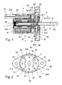
- the rotary magnet 1 is in Fig. 1 in the sectional view shown schematically.
- the rotary magnet 1 consists essentially of a stator 3 and a rotor 5.
- the stator 3 receives the coil 4, the rotor 5 rotates about the axis of rotation 51st
- the stator 3 consists of two parts, namely the casing part 35 and the cover part 36.
- the casing part 35 is designed like a pot and takes up the coil 4.
- the casing part 35 acts as a housing and closes off the rotary magnet 1.
- the outer shape of the shell portion 35 is pot-like, concentric a center pole 34 is provided like a spike, on which the bobbin 41 of the coil 4 can be placed.
- a center pole 34 is provided like a spike, on which the bobbin 41 of the coil 4 can be placed.
- two pivot bearings 55 are provided with respect to the axis of rotation 51 slightly spaced from each other, which radially support the rotor shaft 50 of the rotor 5 in the stator. Seen in the axial direction, the center pole 34 protrudes in the direction of the cover part 36 beyond the end of the coil 4. It thus forms a thorn-like Aufsetznnenkeit, the center pole 34 is disposed coaxially to the axis of rotation 51.
- the coil 4 is formed from a substantially cylindrical bobbin 41, which carries the windings 42.
- the windings 42 consist of an electrically conductive wire. The windings are seated on the bobbin, the bobbin and thus also the windings 42 are arranged in the stator 3 so that they surround the axis of rotation 51.
- only one coil 4 is provided in the stator 3, but without the invention thereof want to restrict. It is also possible to arrange a plurality of coils 4 with respect to the axis of rotation 51 axially one behind the other coaxial with the axis of rotation 51. It is thus possible, for example, in a kind of modular system with few components to realize or adapt a larger number of different rotary magnets 1 with respect to their power development.
- the stator 3 is then configured correspondingly longer.
- the multi-part structure of the stator 3, divided into a shell part 35 and a cover part 36 greatly facilitates the assembly of the rotary magnet according to the invention 1.
- the center pole 34 is sleeve-shaped and hollow inside to receive the rotor shaft 50.
- this is a corresponding collar in the middle pole 34 is provided.
- the stator 3 has a provided in the bottom portion 302 closure member 303, which closes the stator 3 on the free end of the rotor shaft 50 side facing away and through which the rear pivot bearing 55 in the center pole 34 can be installed.
- the cover part 36 is pushed in the axial direction (with respect to the axis of rotation 51) on the casing part 35 and pressed with this.
- the cover part 36 forms the pole face 30 and, in another possible embodiment, can also receive or support the pole faces 31, 32.
- the stator 3 serves to guide the magnetic field, which is generated by the coil 4, when carried by the coil 4 Windings 42 are supplied with electric current.
- the connection between the casing part 35 and the cover part 36 is designed so that a line of the magnetic flux is not obstructed as possible.
- the cover part 36 also has the task of providing an attachment possibility of the rotary magnet 1 according to the invention.
- a preferably protruding on both sides mounting flange 38 is formed on the cover part 36, which has mounting opening 39 through which corresponding fastening screws (not shown) can be performed.
- the rotor 5 has a rotor shaft 50, which is about 1.5 to 3 times, preferably about 1.8 to 2.2 times longer than the length of the stator 3.
- the rotor shaft 50 carries the rotor disk 52. This closes yourself, in Fig. 1 On the left, the area of the rotor shaft 50, which stands in the stator and in which both pivot bearings 55 are mounted.
- a return spring 56 is provided for the rotor.
- the rotor shaft 50 can be connected according to elements that are to be controlled due to the rotational movement of the rotary magnet 1.
- the rotor shaft 50 penetrates a cover plate 300, which covers the rotor disk 52.
- the rotation angle limit 8 is formed by two slot-like recesses or openings 301 in the cover plate 300, which extend in the circumferential direction.
- protruding impact bodies 80 are provided in the openings 301, which are equipped, for example, with an elastomer or consist of an elastomer. Limit these baffles 80 the rotational movement of the rotor. 5
- the rotor disk 52 carries a ring 53 of permanent magnets, whose pole arrangement is chosen so that it is in the circumferential direction, (with respect to the rotation of the rotation axis, about the rotation axis 51) alternately, that is alternating.
- the rotor shaft 50 can carry two rotor disks 52, wherein the coil 4 is then provided between the two rotor disks 52.
- the concept for the magnetic flux distribution is realized on both sides of the coil 4.
- the pole face 30, which faces the second rotor disk 52 is formed from at least two pole face surfaces 31, 32 serving for the magnetic flux guidance of the magnetic field which has been applied by the current applied to the winding of the coil 4.
- this pole face 30 can according to the invention have all the features as described for the first pole face 30.
- the resulting magnetization is also seen with respect to the axis of rotation 51 in the circumferential direction alternately.
- a cascade-like or alternating arrangement of a plurality of coils 4 and / or a plurality of rotor disks 52 is possible and conceivable.
- FIG. 2 the design of the pole face 30 is shown.
- the pole face 30 is divided into two pole faces 31, 32 in the exemplary embodiment shown here.
- the pole piece surface 30 is arranged at right angles to the axis of rotation 51 in the cover part 36.
- the cover part 36 is configured pot-shaped and has a peripheral boundary edge 304.
- This peripheral boundary edge 304 is circular and coaxial with the axis of rotation 51.
- the boundary edge 304 or a part of this boundary edge 304 counts to the Polteil configuration 31, which is arranged as a first Polteil constitutional 31 outside and surrounds the second inner Polteil constitutional 32.
- the pole face 30 and the pole faces 31 and 32 are, as well as the stator 3 in the rest (shell part 35 and cover part 36), made of a soft magnetic material, thus optimally to guide the magnetic field line. These elements are part of the Magnetflußbiees of the stator. 3
- the pole faces 31a, 31b are formed like a ring segment and have an outer diameter which is slightly larger or at least equal to the outer diameter of the middle, second Polteil constitutional 32. It is clear that it does not matter for the invention whether the two Polteil vom 31a, 31b are now connected by the peripheral boundary edge 304 magnetically conductive or not.
- N or S indicates the magnetic poles of the magnetic field generated by the coil. It is favorable that between the Polteil constitutional 32, which also encloses the axis of rotation 51, and the laterally spaced pole faces 31, 31 a, 31 b, a pole gap 33 is made. Alternatively, the pole gap 33 is filled or unfilled. For the magnetic field lines, this pole gap 33 represents a corresponding resistance.
- an alternating arrangement of north (N) and south poles (S) thus forms on the pole face 30.
- This alternating magnetic pole arrangement is located within the peripheral boundary edge 304 but slightly spaced from the axis of rotation 51.
- the arrangement is achieved such that the cover part 36 has a recess 37 into which the inner, second pole piece surface 32 can be inserted.
- the inner, second Polteil compounds 32 is placed on the mandrel-like end of Mittelpoles 34, pressed or pressed.
- the pole piece surface 32 thus also experiences a good magnetic contact with the remaining center pole 34.
- the arrangement is chosen so that the rotor disk 52 facing surface of the pole face 31, 32 are coaxial to each other, so the distance from the divided into a plurality of pole faces 31, 32 pole face 30 to the rotor disk 52 is the same everywhere, which is why an air gap 54 between the pole face 30 and the rotor disk 52 or the ring 53 arranged on the rotor disk 52 results in permanent magnets of the same extent.
- the pole gap 33 extends in the radial direction (with respect to the axis of rotation 51).
- the pole gap 33 is located, seen in the circumferential direction, between the first Polteil requirements 31 and the second Polteil requirements 32.
- the pole gap 33 extends in the radial direction referred to the axis of rotation 51, whereas the width b of the pole gap is perpendicular to the extension of the pole gap 33.
- a Polspalt 33, 33 a Between the end of the second Polteil constitutional 32 and the boundary edge 304 also extends, seen in the circumferential direction, a Polspalt 33, 33 a, the width of which is radially oriented.
- the two opposite, outer regions, which adjoin the central region, are symmetrical to each other and thus equal; they are characterized by a boundary edge running radially to the axis of rotation 51, in order then to terminate in a boundary bend with a larger diameter.
- the arrangement is chosen such that the air gap 54, which is between the ring 53 of permanent magnets (which are disposed on the rotor disk 52) is less than the pole gap 33 between the individual pole faces 31, 32.
- the emerging on the inner, second Polteil composition 32 Magnetic field lines thus have to overcome a shorter distance to the ring 53 of permanent magnets than to the adjacent other pole part surface 31.
- the rotor disk 52 has on its side facing the coil 4, the ring 53 of permanent magnets which are arranged alternately in polarization such that on its surface facing the pole face 30, for example, the pole sequence N-S-N-S, etc. exists.
- the rotation angle limit 8 is provided on the ring 53 facing away from the side of the rotor disk;
- the rotor disk 52 carries baffle body 80.
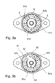
- Fig. 3a and 3b The principle of operation is in particular by the Fig. 3a and 3b described by way of example.
- chosen representation corresponds to in Fig. 2 , wherein on the level of the pole face 30 here still the ring 53 of permanent magnets 57a, 57b, 57c, 57d is shown.
- Fig. 3b For a slightly easier orientation is in Fig. 3b a portion of the ring 53 is broken to show the underlying pole face 30 and Polteil vom 31 and 32, respectively. On these Polteil vom their magnetic poles N and S are arranged, it can clearly be seen that the single permanent magnet 57b is also marked with an S. It follows that an arrangement of a south pole of the permanent magnet 57b over the north pole of the underlying Polteil constitutional 31. It is clear that the magnetization of the permanent magnet 57a, b, c, d is indicated on the pole face 30 side facing.
- Fig. 3a shows the same situation as the Fig. 3b However, the orientation is slightly more difficult due to the superimposed structure.
- the pole of the lying under the ring 53 pole faces 31, 32 were indicated by a dashed line indicated. It is clear that the polarity in the region of the pole face 30 or of the first and second pole faces 31, 32 only arises when the coil 4 is energized accordingly.
- the rotational movement is generated by an attraction or repulsion of the permanent magnet segments 57a, b, c, d. Due to the pole separation at the pole gaps 33, this effect occurs in all four segments, the length of the individual permanent magnet segments corresponds to those in the area of the pole face. The result is a rotational movement of the permanent magnet ring 53 in the counterclockwise direction.
Landscapes
- Engineering & Computer Science (AREA)
- Power Engineering (AREA)
- Physics & Mathematics (AREA)
- Electromagnetism (AREA)
- Electromagnets (AREA)
- Permanent Field Magnets Of Synchronous Machinery (AREA)
- Iron Core Of Rotating Electric Machines (AREA)
- Reciprocating, Oscillating Or Vibrating Motors (AREA)
- Permanent Magnet Type Synchronous Machine (AREA)
Applications Claiming Priority (1)
| Application Number | Priority Date | Filing Date | Title |
|---|---|---|---|
| DE102009060407A DE102009060407A1 (de) | 2009-12-22 | 2009-12-22 | Drehmagnet |
Publications (2)
| Publication Number | Publication Date |
|---|---|
| EP2339718A2 true EP2339718A2 (fr) | 2011-06-29 |
| EP2339718A3 EP2339718A3 (fr) | 2018-07-04 |
Family
ID=43530042
Family Applications (1)
| Application Number | Title | Priority Date | Filing Date |
|---|---|---|---|
| EP10015712.2A Withdrawn EP2339718A3 (fr) | 2009-12-22 | 2010-12-16 | Aimant pivotant |
Country Status (3)
| Country | Link |
|---|---|
| US (1) | US8729994B2 (fr) |
| EP (1) | EP2339718A3 (fr) |
| DE (1) | DE102009060407A1 (fr) |
Families Citing this family (4)
| Publication number | Priority date | Publication date | Assignee | Title |
|---|---|---|---|---|
| DE102011015867A1 (de) * | 2011-04-01 | 2012-10-04 | Svm Schultz Verwaltungs-Gmbh & Co. Kg | Drehmagnet |
| UA111081C2 (uk) * | 2012-07-02 | 2016-03-25 | Шалтбау Гмбх | Електричний контактор з маховичним приводом і спосіб вмикання і/або вимикання електричного контактора |
| DE102013203133A1 (de) * | 2013-02-26 | 2014-08-28 | Schaeffler Technologies Gmbh & Co. Kg | Aktoreinheit mit Rotationsstelleinrichtung |
| US12555732B2 (en) * | 2022-04-20 | 2026-02-17 | Sensata Technologies, Inc. | Electromechanical rotary latch for use in current interruption devices |
Family Cites Families (5)
| Publication number | Priority date | Publication date | Assignee | Title |
|---|---|---|---|---|
| GB1262855A (en) * | 1968-02-21 | 1972-02-09 | Smiths Industries Ltd | Improvements in or relating to rotary solenoids |
| US4207483A (en) * | 1978-09-01 | 1980-06-10 | Warner Electric Brake & Clutch Co. | Step motor with circumferential stators on opposite sides of disc-like rotor |
| JPS5661102A (en) * | 1979-10-24 | 1981-05-26 | Aisin Seiki Co Ltd | Rotary solenoid |
| DE3317426A1 (de) * | 1983-05-13 | 1984-11-15 | Schramme GmbH, 7778 Markdorf | Drehmagnet |
| FR2717947B1 (fr) * | 1994-03-25 | 1996-05-31 | Sagem | Actionneur électromagnétique rotatif à débattement angulaire limité. |
-
2009
- 2009-12-22 DE DE102009060407A patent/DE102009060407A1/de not_active Ceased
-
2010
- 2010-12-16 EP EP10015712.2A patent/EP2339718A3/fr not_active Withdrawn
- 2010-12-20 US US12/972,576 patent/US8729994B2/en not_active Expired - Fee Related
Non-Patent Citations (1)
| Title |
|---|
| None |
Also Published As
| Publication number | Publication date |
|---|---|
| US20110187483A1 (en) | 2011-08-04 |
| DE102009060407A1 (de) | 2011-06-30 |
| EP2339718A3 (fr) | 2018-07-04 |
| US8729994B2 (en) | 2014-05-20 |
Similar Documents
| Publication | Publication Date | Title |
|---|---|---|
| DE3427677C2 (fr) | ||
| DE102006026719B4 (de) | Klauenpolstator für einen Schrittmotor und Klauenpol-Schrittmotor | |
| DE10140303A1 (de) | Unipolar-Transversalflußmaschine | |
| EP0286905A1 (fr) | Moteur à courant continu à commutation électronique | |
| EP0574960B1 (fr) | Moteur électrique rotatif | |
| EP3596811A1 (fr) | Machine électrique | |
| WO2016096190A1 (fr) | Dispositif et procédé de magnétisation d'aimants permanents | |
| DE3641369C2 (fr) | ||
| EP2506407B1 (fr) | Aimant rotatif | |
| DE102013206897A1 (de) | Elektromagnetischer Aktuator | |
| EP2997644A2 (fr) | Rotor pour machine électromécanique | |
| DE102009060407A1 (de) | Drehmagnet | |
| DE102012218995A1 (de) | Läuferanordnung für eine permanentmagneterregte elektrische Maschine | |
| DE3786392T2 (de) | Elektromagnetische antriebsvorrichtung. | |
| DE4417903C2 (de) | Aufmagnetisierungsvorrichtung für elektrische Maschinen mit Dauermagnetläufer | |
| DE102016212328A1 (de) | Rotoranordnung einer elektrischen Maschine | |
| DE10055080C2 (de) | Elektrische Linearmaschine | |
| DE19510925B4 (de) | Elektromagnetische Drehbetätigungsvorrichtung mit begrenztem Winkelschwenkbereich | |
| EP3457529B1 (fr) | Moteur à induit en disque | |
| EP2909921A2 (fr) | Ensemble stator pour une machine électrique à excitation par aimants permanents | |
| EP1233497B1 (fr) | Machine électrique excitée par aimant permanent | |
| DE102005049022B4 (de) | Drehmagnet | |
| WO1994004807A1 (fr) | Organe correcteur pour ajuster l'angle de rotation d'un element de reglage | |
| EP1928073A2 (fr) | Moteur électrique sans balais | |
| DE102017218815A1 (de) | Magnetanordnung für eine elektrische Maschine |
Legal Events
| Date | Code | Title | Description |
|---|---|---|---|
| PUAI | Public reference made under article 153(3) epc to a published international application that has entered the european phase |
Free format text: ORIGINAL CODE: 0009012 |
|
| AK | Designated contracting states |
Kind code of ref document: A2 Designated state(s): AL AT BE BG CH CY CZ DE DK EE ES FI FR GB GR HR HU IE IS IT LI LT LU LV MC MK MT NL NO PL PT RO RS SE SI SK SM TR |
|
| AX | Request for extension of the european patent |
Extension state: BA ME |
|
| PUAL | Search report despatched |
Free format text: ORIGINAL CODE: 0009013 |
|
| AK | Designated contracting states |
Kind code of ref document: A3 Designated state(s): AL AT BE BG CH CY CZ DE DK EE ES FI FR GB GR HR HU IE IS IT LI LT LU LV MC MK MT NL NO PL PT RO RS SE SI SK SM TR |
|
| AX | Request for extension of the european patent |
Extension state: BA ME |
|
| RIC1 | Information provided on ipc code assigned before grant |
Ipc: H02K 26/00 20060101ALI20180525BHEP Ipc: H01F 7/08 20060101AFI20180525BHEP |
|
| STAA | Information on the status of an ep patent application or granted ep patent |
Free format text: STATUS: REQUEST FOR EXAMINATION WAS MADE |
|
| 17P | Request for examination filed |
Effective date: 20190102 |
|
| RBV | Designated contracting states (corrected) |
Designated state(s): AL AT BE BG CH CY CZ DE DK EE ES FI FR GB GR HR HU IE IS IT LI LT LU LV MC MK MT NL NO PL PT RO RS SE SI SK SM TR |
|
| STAA | Information on the status of an ep patent application or granted ep patent |
Free format text: STATUS: EXAMINATION IS IN PROGRESS |
|
| 17Q | First examination report despatched |
Effective date: 20200312 |
|
| STAA | Information on the status of an ep patent application or granted ep patent |
Free format text: STATUS: THE APPLICATION HAS BEEN WITHDRAWN |
|
| 18W | Application withdrawn |
Effective date: 20210524 |