EP2339719A2 - Rotierende elektrische Permanentmagnetmaschine - Google Patents
Rotierende elektrische Permanentmagnetmaschine Download PDFInfo
- Publication number
- EP2339719A2 EP2339719A2 EP10015990A EP10015990A EP2339719A2 EP 2339719 A2 EP2339719 A2 EP 2339719A2 EP 10015990 A EP10015990 A EP 10015990A EP 10015990 A EP10015990 A EP 10015990A EP 2339719 A2 EP2339719 A2 EP 2339719A2
- Authority
- EP
- European Patent Office
- Prior art keywords
- permanent magnet
- side face
- slot
- rotor core
- rotor
- Prior art date
- Legal status (The legal status is an assumption and is not a legal conclusion. Google has not performed a legal analysis and makes no representation as to the accuracy of the status listed.)
- Granted
Links
Images



Classifications
-
- H—ELECTRICITY
- H02—GENERATION; CONVERSION OR DISTRIBUTION OF ELECTRIC POWER
- H02K—DYNAMO-ELECTRIC MACHINES
- H02K1/00—Details of the magnetic circuit
- H02K1/06—Details of the magnetic circuit characterised by the shape, form or construction
- H02K1/22—Rotating parts of the magnetic circuit
- H02K1/27—Rotor cores with permanent magnets
- H02K1/2706—Inner rotors
- H02K1/272—Inner rotors the magnetisation axis of the magnets being perpendicular to the rotor axis
- H02K1/274—Inner rotors the magnetisation axis of the magnets being perpendicular to the rotor axis the rotor consisting of two or more circumferentially positioned magnets
- H02K1/2753—Inner rotors the magnetisation axis of the magnets being perpendicular to the rotor axis the rotor consisting of two or more circumferentially positioned magnets the rotor consisting of magnets or groups of magnets arranged with alternating polarity
- H02K1/276—Magnets embedded in the magnetic core, e.g. interior permanent magnets [IPM]
- H02K1/2766—Magnets embedded in the magnetic core, e.g. interior permanent magnets [IPM] having a flux concentration effect
Definitions
- the present invention relates to a permanent magnet type rotating electric machine and more particularly to a permanent magnet type rotating electric machine suitable for the type having a permanent magnet in a rotor core.
- a surface magnet type rotating electric machine having a rotor structure in which plural magnets are attached to an outer periphery of a rotor core formed by laminating silicon steel plates in an axial direction of the rotor core, and a interior permanent magnet type rotating electric machine in which slots are formed near an outer periphery of a rotor core so as to be extended in the axial direction of the rotor core and permanent magnets are inserted into the slots respectively.
- each insertion slot for the permanent magnet in the rotor core since is formed by axially aligning holes formed by respectively punching silicon steel plates to be laminated, asperities trend to present on the slot in the axial direction due to tolerances of holes.
- an adhesive is used mainly in small-sized rotating electric machines which are not so strictly required to satisfy high strength and high reliability.
- the adhesive has a disadvantage in that the adhesive force thereof deteriorates due to, for example, aged deterioration.
- an induction motor having rotor bars inserted into slots of a rotor core and an end ring attached to front ends of the rotor bars, a natural frequency of torsional vibration induced by those rotor bars and end ring is likely to be lowered.
- JP 2000-341891A shows a technique of adopting a structure in which the rotor bars are constantly pressed against a side where the rotor bars are pressed with a rotary force of the rotor during rotation thereof.
- JP-A 2009-22089 shows a technique for making small the spacing between outer periphery portions of permanent magnets 3 and stator magnetic poles while keeping balance between magnetic characteristics and strength for bearing a centrifugal force.
- JP 2002-101585A and H9 show such a technique as shown in Fig. 11 in which both ends of outer periphery portions of permanent magnets 3 are exposed from a rotor core 2 and the permanent magnets 3 are fixed by a non-magnetic sleeve.
- each slot for insertion therein of a permanent magnet of the rotor is formed by axially aligned holes formed by respectively punching silicon steel plates to be laminated, asperities may present on the slot in the axial direction due to tolerances on holes. Due to the asperities caused by the tolerances, therefore, it is likely that a frictional force induced at the time of inserting the permanent magnet into the slot will become large, making it impossible to effect the insertion of the magnet. To avoid this inconvenience, a large slot (holes) relative to the shape of a magnet is formed, thus causing a clearance to be formed between the magnet and the slot. In this case, however, since the permanent magnet is a fragile material in point of strength, the presence of a clearance between the magnet and the magnet insertion slot is likely to cause cracking due to vibration or the like.
- the present invention has been accomplished in view of the above-mentioned point and it is an object of the invention to provide a permanent magnet type rotating electric machine in which a permanent magnet, though fragile in point of strength, does not move through a slot of a rotor core under, for example, vibration during operation and is hence not cracked by vibration or the like.
- a permanent magnet type rotating electric machine of the present invention is characterized as follows basically. It is comprised of a rotor and a stator opposed to each other keeping a predetermined clearance therebetween, the rotor having a rotor core formed by silicon steel plates being laminated in an axial direction of the rotor core, slots being formed near an outer periphery of the rotor core in the rotor core so as to be open at the outer periphery of the rotor core, permanent magnets being inserted into the slots respectively, and a non-magnetic sleeve covering the outer periphery of the rotor core, wherein each of the slots has inclined side faces outwardly broadening the slot in a radial direction of the rotor core, and each of the permanent magnets is fixed into the slot with a force applied from the sleeve so as to directing toward a center of the rotor core and an pressure applied from the inclined
- the present invention it is possible to provide a permanent magnet type rotating electric machine which is able to easily insert a permanent magnet into a slot because of the slot outwardly broadening in the radial direction of the rotor core, and prevent rattling of the permanent magnet within the slot even if the permanent magnet is formed of a fragile material in point of strength.
- Fig. 1 shows a rotor for explaining a permanent magnet type rotating electric machine according to a first embodiment of the present invention.
- the permanent magnet type rotating electric machine of this embodiment shown in Fig. 1 comprises a rotor 1 and a stator (not shown) opposed to each other keeping a predetermined clearance therebetween.
- the rotor 1 is comprised of a rotor core 2 formed by silicon steel plates laminated in an axial direction of the rotor core, slots 4 being formed near an outer periphery of the rotor core 2 in the rotor core so as to be open at the outer periphery of the rotor core 2, permanent magnets 3 being inserted into the slots 4 respectively, and a non-magnetic sleeve 7 covering the outer periphery of the rotor core 2.
- the non-magnetic sleeve 7 is fitted by shrink fit or forced fit.
- Each of cavities 10 is disposed between adjacent slots 4 near the outer periphery of the rotor core 2 to generate reluctance torque.
- each of the slots 4 being open at the outer periphery surface of the rotor core 2 has inclined side faces 4a (which are inclined with respect to a vertical center line of the slot 4) outwardly broadening (e.g. fanning out) the slot 4 in the radial direction of the rotor core 2.
- Each of the permanent magnets 3 has a wedge-shaped form and is fixed into the slot 4 with a force C applied from the sleeve 7 (the force C directing toward a center of the rotor core 2) and an pressure applied from the inclined side faces 4a of the slot 4 as shown in black allows D in Fig. 1 , for example by adopting an interference fit or a tight fit.
- a conventional permanent magnet type rotating electric machine as shown in Fig. 12 has parallel side faces 40a of each slot 40 and parallel both faces of each permanent magnet 30 inserted into the slot 40.
- a resultant force of both a centrifugal force of the rotor 1 and an electromagnetic force generated by stator is applied to the rotor core 20 and each permanent magnet 30.
- stator not shown
- an interference 5 is provided at an outer periphery end of each permanent magnet 3, and the permanent magnet 3 is applied with a force pressing the permanent magnet 3 into the slot 4 by working of both the interference 5 and a hoop stress of the sleeve 7. Then an initial surface pressure for fixing the permanent magnet 3 is applied to the permanent magnet 3 by the force C pressing the magnet 3 into the slot 4 and a force (stress) D applied to the wedge-shaped permanent magnet 3 from the inclined side faces 4a of the slot 4.
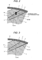
- Fig. 2 is a partial sectional view of a rotor core in a permanent magnet type rotating electric machine according to a second embodiment of the present invention.
- the rotor 1 of this embodiment also comprises a rotor core 2 with slots 4 each having inclined side faces 4a outwardly broadening the slot 4 in the radial direction of the rotor core 2, permanent magnets 3 each having a wedge-shaped form, and a non-magnetic sleeve 7 similarly with the first embodiment.
- the technical matters different from the first embodiment is as follows.
- each insertion slot 4 for the permanent magnet 3 is formed by axially aligning holes formed by respectively punching silicon steel plates to be laminated, asperities may present on the slot in the axial direction. Even at a small tolerance, therefore, a frictional force developed upon insertion of the permanent magnet becomes large, the insertion of a permanent magnet may become impossible due to a large frictional force induced at the time of insertion of the magnet. To avoid this inconvenience, in the conventional art, a large slot (aligned holes) relative to the shape of the permanent magnet is formed, thereby causing a clearance between the permanent magnet and the slot.
- one inclined side face which is opposite to another inclined side face subjected to a pressure of the permanent magnet 3 with a resultant force of both a centrifugal force of the rotor 1 and an electromagnetic force generated by stator (not shown), is provided with a first side face part 9a tightly fitting to a part of the permanent magnet 3 so as to press the magnet 3 against the first side face part 9a and a second side face part 9b as a cut face with a step height increasing the clearance between the second side face part 9a and the permanent magnet 3 so as to be greater than the manufacturing tolerance.
- the second side face part (cut face) 9b is formed over a range from an opening side of the slot 4 (an outer periphery-side of the rotor) to at least approximately middle deep point of the slot 4 on the one inclined side face 4a to easily insert the permanent magnet 3 into the slot 4.
- the face 9a is formed near a slot's bottom side opposite to the opening side of the slot 4 on the one inclined side face 4a.
- Fig. 3 is a partial sectional view of a rotor core in a permanent magnet type rotating electric machine according to a third embodiment of the present invention.
- the rotor 1 of this embodiment also comprises a rotor core 2 with slots 4 each having inclined side faces 4a outwardly broadening the slot 4 in the radial direction of the rotor core 2, permanent magnets 3 each having a wedge-shaped form, and a non-magnetic sleeve 7 similarly with the first and second embodiments.
- one inclined side face which is opposite to another inclined side face subjected to a pressure of the permanent magnet 3 with a resultant force of both a centrifugal force of the rotor 1 and an electromagnetic force generated by the stator (not shown), is provided with a first side face part 9a tightly fitting to a part of the permanent magnet 3 so as to press the magnet 3 against the side face part 9a.
- a second side face part 9b of the present embodiment is different from that of the second embodiment in form.
- the second side face part 9b of the present embodiment is inclined so as to gradually increase a clearance between the inclined side face 4a (the second side face part 9b) and the permanent magnet 3 toward an outer periphery-side of the rotor.
- the second side face part 9b is formed over a range from an opening side of the slot 4 (an outer periphery-side of the rotor) to at least approximately middle deep point of the slot 4 on the one inclined side face 4a to easily insert the permanent magnet 3 into the slot 4.
- such a configuration can obtain the same effect as that of the second embodiment.
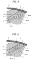
- Fig. 4 is a partial sectional view of a rotor core in a permanent magnet type rotating electric machine according to a fourth embodiment of the present invention.
- the rotor 1 of this embodiment also comprises a rotor core 2 with slots 4 each having inclined side faces 4a outwardly broadening the slot 4 in the radial direction of the rotor core 2, permanent magnets 3 each having a wedge-shaped form, and a non-magnetic sleeve 7 similarly with the first and second embodiments.
- one inclined side face which is opposite to another inclined side face subjected to a pressure of the permanent magnet 3 with a resultant force of both a centrifugal force of the rotor 1 and an electromagnetic force generated by the stator (not shown), is provided with a first side face part 9a tightly fitting to a part of the permanent magnet 3 so as to press the magnet 3 against the side face part 9a.
- a second side face part 9b as a cut face with a step height increasing the clearance between the inclined side face 4a and the permanent magnet 3 so as to be greater than the manufacturing tolerance.
- first side face part 9a and second side face part 9b of the present embodiment is different from that of the second embodiment in form. That is, the first side face part 9a is separated into two parts which are disposed both ends side in a deep direction of the slot 4, namely into the opening side and the bottom side in the slot 4.
- the second side face part 9b is disposed between the two parts of the first side face part 9a. In the embodiment shown in Fig. 4 , such a configuration can obtain the same effect as that of the second embodiment.
- Fig. 5 is a partial sectional view of a rotor core in a permanent magnet type rotating electric machine according to a fifth embodiment of the present invention.
- the rotor 1 of this embodiment also comprises a rotor core 2 with slots 4 each having inclined side faces 4a outwardly broadening the slot 4 in the radial direction of the rotor core 2, permanent magnets 3 each having a wedge-shaped form, and a non-magnetic sleeve 7 similarly with the first and second embodiments.
- one inclined side face which is opposite to another inclined side face subjected to a pressure of the permanent magnet 3 with a resultant force of both a centrifugal force of the rotor 1 and an electromagnetic force generated by the stator (not shown), is provided with a first side face part 9a tightly fitting to a part of the permanent magnet 3 so as to press the magnet 3 against the side face part 9a.
- a second side face part 9b as a cut face with a step height increasing the clearance between the inclined side face 4a and the permanent magnet 3 so as to be greater than the manufacturing tolerance.
- first side face part 9a and second side face part 9b of the present embodiment is different from that of the second embodiment in form. That is, the first side face part 9a is disposed at a middle point on the one side face 4a and the second side face 9b is separated into two parts which are disposed both sides with respect to the first side face part 9a (middle point)in a deep direction of the slot 4. In the embodiment shown in Fig. 5 , such a configuration can also obtain the same effect as that of the second embodiment.
- Fig. 6 is a partial sectional view of a rotor core in a permanent magnet type rotating electric machine according to a sixth embodiment of the present invention and Fig. 7 is a partial enlarged view of Fig. 6 .
- the present embodiment's features different from the above-mentioned other embodiments are as follows.
- the present embodiment has parallel (opposed) side faces 4a' of each slot 4' in place of outwardly broadening inclined side faces 4a of the slot 4 described in the first to fifth embodiments, and has parallel both faces of each non wedge-shaped permanent magnet 3' inserted into the slot 4' .
- one parallel side face (indicated by numeral 9b'), which is opposite to another parallel side face subjected to a pressure of the permanent magnet 3' with a resultant force of both a centrifugal force of the rotor 1 and an electromagnetic force generated by the stator (not shown), is provided with a cut face 9b' increasing a clearance between the one parallel side face 4a' and the permanent magnet 3' so as to be greater than the manufacturing tolerance.
- the one side face 4a' as the cut face 9b' is shorter than another side face 4a', and an inclined side face 9a' is provided between the cut face 9b' and the bottom of the slot 4' .
- the inclined side face 9a' near a slot' s one end portion is also located on the side opposite to another inclined side face 4a' subjected to the pressure of the permanent magnet 3' with the resultant force of both the centrifugal force of the rotor 1 and the electromagnetic force.
- the permanent magnet 3' is applied with a force pressing the permanent magnet 3' into the slot 4 by the sleeve 7, and thereby one corner of the permanent magnet 3' is pressed against the inclined side face 9a'. Therefore, the permanent magnet 3' is surely fixed by the force pressing the magnet 3' into the slot 4' by the sleeve7, the force (stress) applied to the permanent magnet 3' from the inclined side faces 9a', and the force pressing the permanent magnet 3' against the another side face 4a' with the resultant force of both the centrifugal force of the rotor 1 and the electromagnetic force.
- Fig. 8 is a partial sectional view of a rotor core in a permanent magnet type rotating electric machine according to a seventh embodiment of the present invention.
- the rotor 1 of this embodiment also comprises a rotor core 2 with slots 4 each having inclined side faces 4a outwardly broadening the slot 4 in the radial direction of the rotor core 2, permanent magnets 3 each having a wedge-shaped form, and a non-magnetic sleeve 7 similarly with the first embodiment.
- the technical matters different from the first embodiment is as follows.
- an elastic member 11 is inserted between the sleeve 7 and a slot open-side end portion of each permanent magnet 3 thereby to allow the elastic member 11 to keep a force pressing the permanent magnet 3 toward the rotor core center side of each slot 4'.
- the following effect is obtained. That is, even if the interference effect at the slot-open side end portion of the permanent magnet 3 is gone due to a thermal deformation difference such as a thermal expansion difference, the permanent magnet 3 can be surely held with a reaction force of the elastic member 11.
- the elastic member 11 is interposed between the slot open-side end portion of the permanent magnet 3 and the sleeve 7, it can be not necessary to machine the slot open-side end portion of the permanent magnet in conformity with the outer periphery of the rotor and the sleeve 7.
- Fig. 9 is a partial sectional view of a rotor core in a permanent magnet type rotating electric machine according to an eighth embodiment of the present invention.
- This embodiment is a modified example of the seventh embodiment and the technical matter different from the seventh embodiment is as follows.
- a slot-side end portion of a permanent magnet 3 is cut by a predetermined thickness with respect to the outer periphery of a rotor and an elastic member 11 having a predetermined uniform thickness is inserted into the thus-cut space namely between the slot open-side end portion of the permanent magnet 3 and the sleeve 7.
Landscapes
- Engineering & Computer Science (AREA)
- Power Engineering (AREA)
- Permanent Field Magnets Of Synchronous Machinery (AREA)
- Iron Core Of Rotating Electric Machines (AREA)
Applications Claiming Priority (1)
| Application Number | Priority Date | Filing Date | Title |
|---|---|---|---|
| JP2009291702A JP5292271B2 (ja) | 2009-12-24 | 2009-12-24 | 永久磁石式回転電機 |
Publications (3)
| Publication Number | Publication Date |
|---|---|
| EP2339719A2 true EP2339719A2 (de) | 2011-06-29 |
| EP2339719A3 EP2339719A3 (de) | 2014-01-29 |
| EP2339719B1 EP2339719B1 (de) | 2016-03-30 |
Family
ID=43561954
Family Applications (1)
| Application Number | Title | Priority Date | Filing Date |
|---|---|---|---|
| EP10015990.4A Not-in-force EP2339719B1 (de) | 2009-12-24 | 2010-12-22 | Rotierende elektrische Permanentmagnetmaschine |
Country Status (5)
| Country | Link |
|---|---|
| US (1) | US20110156521A1 (de) |
| EP (1) | EP2339719B1 (de) |
| JP (1) | JP5292271B2 (de) |
| KR (1) | KR101177416B1 (de) |
| CN (1) | CN102111027B (de) |
Cited By (2)
| Publication number | Priority date | Publication date | Assignee | Title |
|---|---|---|---|---|
| EP2667483A3 (de) * | 2012-05-25 | 2014-03-19 | Jtekt Corporation | Rotor und Motor mit einem Rotor |
| EP2988395A4 (de) * | 2013-04-16 | 2017-03-22 | NHK Spring Co., Ltd. | Magnetplatte für rotorkern eines motors und verfahren zur herstellung einer magnetischen platte |
Families Citing this family (17)
| Publication number | Priority date | Publication date | Assignee | Title |
|---|---|---|---|---|
| JP2012157150A (ja) * | 2011-01-26 | 2012-08-16 | Hitachi Ltd | 永久磁石式回転電機 |
| CN102306963A (zh) * | 2011-09-14 | 2012-01-04 | 天津市松正电动汽车技术股份有限公司 | 一种永磁电机转子 |
| JP5851365B2 (ja) * | 2012-08-31 | 2016-02-03 | 日立オートモティブシステムズ株式会社 | 回転電機 |
| DE112013007067T5 (de) * | 2013-05-13 | 2016-01-28 | Mitsubishi Electric Corporation | Rotor mit eingebetteten Magneten für eine drehende elektrische Maschine |
| JP2015226371A (ja) * | 2014-05-27 | 2015-12-14 | 富士電機株式会社 | 永久磁石埋め込み式回転電機 |
| KR102491659B1 (ko) | 2015-10-08 | 2023-01-26 | 삼성전자주식회사 | 영구자석 내측 배치형 비엘디씨 모터 |
| JP2017147904A (ja) * | 2016-02-19 | 2017-08-24 | 株式会社ジェイテクト | アキシャルギャップ型回転電機のロータ |
| CN105529841A (zh) * | 2016-02-28 | 2016-04-27 | 天津市革能科技有限公司 | 一种电机用组合式钕铁硼机构 |
| TWM576750U (zh) | 2017-07-25 | 2019-04-11 | 美商米沃奇電子工具公司 | 電氣組合物、電動化裝置系統、電池組、電馬達、馬達總成及電馬達總成 |
| CN109728664B (zh) * | 2017-10-31 | 2020-07-03 | 大银微系统股份有限公司 | 具防护机构的马达转子 |
| EP3917708A4 (de) | 2019-02-18 | 2022-11-30 | Milwaukee Electric Tool Corporation | Schlagwerkzeug |
| US20230116012A1 (en) * | 2020-04-20 | 2023-04-13 | Mitsubishi Electric Corporation | Rotor, motor, compressor, air conditioner, and manufacturing method of rotor |
| JP7382293B2 (ja) * | 2020-07-10 | 2023-11-16 | 東芝三菱電機産業システム株式会社 | 塊状回転子、回転電機、および回転子スロット形成方法 |
| JP7378369B2 (ja) * | 2020-09-09 | 2023-11-13 | 日立Astemo株式会社 | 回転電機の回転子、回転電機及び電動駆動装置 |
| US12088146B2 (en) * | 2021-08-24 | 2024-09-10 | GM Global Technology Operations LLC | Rotor for an electric machine, electric machine for a vehicle, and vehicle |
| DE102022115420A1 (de) * | 2022-06-21 | 2023-12-21 | Dr. Ing. H.C. F. Porsche Aktiengesellschaft | Rotor und elektrische Maschine eines Elektrofahrzeugs |
| DE102024121002A1 (de) * | 2024-07-24 | 2026-01-29 | Dr. Ing. H.C. F. Porsche Aktiengesellschaft | Rotor einer als permanenterregte Synchronmaschine ausgebildeten elektrischen Maschine, elektrische Maschine und Kraftfahrzeug |
Citations (4)
| Publication number | Priority date | Publication date | Assignee | Title |
|---|---|---|---|---|
| JPH0984283A (ja) | 1995-09-18 | 1997-03-28 | Honda Motor Co Ltd | ロータに対するロータ用磁石の配設構造 |
| JP2000341891A (ja) | 1999-05-27 | 2000-12-08 | Hitachi Ltd | 誘導電動機の回転子 |
| JP2002101585A (ja) | 2000-09-25 | 2002-04-05 | Nissan Motor Co Ltd | 同期電動機のロータ構造 |
| JP2009022089A (ja) | 2007-07-11 | 2009-01-29 | Hitachi Ltd | 永久磁石式回転電機、及び永久磁石式回転電機システム |
Family Cites Families (12)
| Publication number | Priority date | Publication date | Assignee | Title |
|---|---|---|---|---|
| JP2792083B2 (ja) * | 1989-03-17 | 1998-08-27 | 松下電器産業株式会社 | 永久磁石回転子 |
| US5063318A (en) * | 1989-08-25 | 1991-11-05 | Sundstrand Corporation | Preloaded permanent magnet rotor assembly |
| US5191256A (en) * | 1989-12-15 | 1993-03-02 | American Motion Systems | Interior magnet rotary machine |
| JPH10136596A (ja) * | 1996-10-29 | 1998-05-22 | Aichi Emerson Electric Co Ltd | 電動機 |
| JP2001314052A (ja) * | 2000-02-25 | 2001-11-09 | Nissan Motor Co Ltd | 同期電動機のロータ構造 |
| JP2002252956A (ja) * | 2001-02-26 | 2002-09-06 | Hitachi Ltd | 永久磁石式回転電機およびそれを用いた圧縮機 |
| US6984909B2 (en) * | 2002-03-29 | 2006-01-10 | Matsushita Electric Industrial Co., Ltd. | Motor |
| JP2004104962A (ja) * | 2002-09-12 | 2004-04-02 | Toshiba Industrial Products Manufacturing Corp | 永久磁石式リラクタンス型回転電機 |
| JP2004328963A (ja) * | 2003-04-28 | 2004-11-18 | Nissan Motor Co Ltd | 電動機の回転子の製造方法及び電動機の回転子 |
| JP5134846B2 (ja) * | 2007-03-26 | 2013-01-30 | 株式会社東芝 | 永久磁石電動機ドライブシステム |
| JP5161612B2 (ja) * | 2008-02-22 | 2013-03-13 | 株式会社東芝 | 永久磁石式回転電機、永久磁石式回転電機の組立方法及び永久磁石式回転電機の分解方法 |
| JP4627788B2 (ja) * | 2008-06-27 | 2011-02-09 | 株式会社日立製作所 | 永久磁石式回転電機 |
-
2009
- 2009-12-24 JP JP2009291702A patent/JP5292271B2/ja not_active Expired - Fee Related
-
2010
- 2010-12-21 US US12/974,644 patent/US20110156521A1/en not_active Abandoned
- 2010-12-22 KR KR1020100132445A patent/KR101177416B1/ko not_active Expired - Fee Related
- 2010-12-22 EP EP10015990.4A patent/EP2339719B1/de not_active Not-in-force
- 2010-12-23 CN CN201010608780.XA patent/CN102111027B/zh not_active Expired - Fee Related
Patent Citations (4)
| Publication number | Priority date | Publication date | Assignee | Title |
|---|---|---|---|---|
| JPH0984283A (ja) | 1995-09-18 | 1997-03-28 | Honda Motor Co Ltd | ロータに対するロータ用磁石の配設構造 |
| JP2000341891A (ja) | 1999-05-27 | 2000-12-08 | Hitachi Ltd | 誘導電動機の回転子 |
| JP2002101585A (ja) | 2000-09-25 | 2002-04-05 | Nissan Motor Co Ltd | 同期電動機のロータ構造 |
| JP2009022089A (ja) | 2007-07-11 | 2009-01-29 | Hitachi Ltd | 永久磁石式回転電機、及び永久磁石式回転電機システム |
Non-Patent Citations (2)
| Title |
|---|
| ELECTRIC MACHINES, vol. 6, 2007, pages 12 - 14 |
| TOSHIBA REVIEW, vol. 55, no. 9, 2000 |
Cited By (3)
| Publication number | Priority date | Publication date | Assignee | Title |
|---|---|---|---|---|
| EP2667483A3 (de) * | 2012-05-25 | 2014-03-19 | Jtekt Corporation | Rotor und Motor mit einem Rotor |
| US9300175B2 (en) | 2012-05-25 | 2016-03-29 | Jtekt Corporation | Rotor and motor including rotor |
| EP2988395A4 (de) * | 2013-04-16 | 2017-03-22 | NHK Spring Co., Ltd. | Magnetplatte für rotorkern eines motors und verfahren zur herstellung einer magnetischen platte |
Also Published As
| Publication number | Publication date |
|---|---|
| JP2011135667A (ja) | 2011-07-07 |
| EP2339719A3 (de) | 2014-01-29 |
| KR20110074460A (ko) | 2011-06-30 |
| US20110156521A1 (en) | 2011-06-30 |
| KR101177416B1 (ko) | 2012-08-27 |
| EP2339719B1 (de) | 2016-03-30 |
| CN102111027A (zh) | 2011-06-29 |
| JP5292271B2 (ja) | 2013-09-18 |
| CN102111027B (zh) | 2014-09-10 |
Similar Documents
| Publication | Publication Date | Title |
|---|---|---|
| EP2339719B1 (de) | Rotierende elektrische Permanentmagnetmaschine | |
| JP5793077B2 (ja) | ロータ及び回転電気機械 | |
| CN103004056B (zh) | 旋转电机用转子芯及其制造方法 | |
| US10727707B2 (en) | Reluctance rotor lamination having an opening for stress reduction | |
| EP0582721A1 (de) | Rotor eines synchronmotors | |
| EP2433348B1 (de) | Elektromotor mit einem permanentmagnetrotor | |
| JP6836842B2 (ja) | ロータおよびこれを含むモータ | |
| US8063530B2 (en) | Permanent magnet rotor with projections for fixing the permanent magnets of the rotor packet | |
| CN106877536B (zh) | 电动机的永磁体转子 | |
| US9015926B2 (en) | Method for producing a motor rotor | |
| CN106165256A (zh) | 永久磁铁式旋转电机及其制造方法 | |
| US10742082B2 (en) | Fixation system for a permanent magnet rotor | |
| EP3018802B1 (de) | Verfahren zur herstellung eines rotors | |
| JP5793078B2 (ja) | T字形磁石ウェッジを備えた回転電気機械用内部ロータ | |
| CN116231913A (zh) | 具有支撑装置的转子、有转子的电机和具有电机的机动车 | |
| CN112823464A (zh) | 用于电动机的转子、用于制造转子的方法以及电动机 | |
| EP2249465A1 (de) | Elektrische drehmaschine | |
| CN103797688B (zh) | 旋转电机的转子 | |
| JP2000152535A (ja) | 永久磁石電動機の回転子 | |
| JP4351482B2 (ja) | 磁石埋込型ロータ及び磁石埋込型ロータの製造方法 | |
| JP5901436B2 (ja) | 永久磁石同期機 | |
| JP2016105696A (ja) | 永久磁石同期機 | |
| KR100648839B1 (ko) | 하이브리드 전기자동차용 영구자석 매입형 동기전동기의회전자 코어 구조 | |
| JP2009284720A (ja) | 永久磁石形同期電動機 | |
| CN103636102B (zh) | 旋转电机的转子 |
Legal Events
| Date | Code | Title | Description |
|---|---|---|---|
| PUAI | Public reference made under article 153(3) epc to a published international application that has entered the european phase |
Free format text: ORIGINAL CODE: 0009012 |
|
| 17P | Request for examination filed |
Effective date: 20110428 |
|
| AK | Designated contracting states |
Kind code of ref document: A2 Designated state(s): AL AT BE BG CH CY CZ DE DK EE ES FI FR GB GR HR HU IE IS IT LI LT LU LV MC MK MT NL NO PL PT RO RS SE SI SK SM TR |
|
| AX | Request for extension of the european patent |
Extension state: BA ME |
|
| PUAL | Search report despatched |
Free format text: ORIGINAL CODE: 0009013 |
|
| AK | Designated contracting states |
Kind code of ref document: A3 Designated state(s): AL AT BE BG CH CY CZ DE DK EE ES FI FR GB GR HR HU IE IS IT LI LT LU LV MC MK MT NL NO PL PT RO RS SE SI SK SM TR |
|
| AX | Request for extension of the european patent |
Extension state: BA ME |
|
| RIC1 | Information provided on ipc code assigned before grant |
Ipc: H02K 1/27 20060101AFI20131220BHEP |
|
| GRAP | Despatch of communication of intention to grant a patent |
Free format text: ORIGINAL CODE: EPIDOSNIGR1 |
|
| INTG | Intention to grant announced |
Effective date: 20150924 |
|
| GRAS | Grant fee paid |
Free format text: ORIGINAL CODE: EPIDOSNIGR3 |
|
| GRAA | (expected) grant |
Free format text: ORIGINAL CODE: 0009210 |
|
| AK | Designated contracting states |
Kind code of ref document: B1 Designated state(s): AL AT BE BG CH CY CZ DE DK EE ES FI FR GB GR HR HU IE IS IT LI LT LU LV MC MK MT NL NO PL PT RO RS SE SI SK SM TR |
|
| REG | Reference to a national code |
Ref country code: GB Ref legal event code: FG4D |
|
| REG | Reference to a national code |
Ref country code: CH Ref legal event code: EP |
|
| REG | Reference to a national code |
Ref country code: AT Ref legal event code: REF Ref document number: 786338 Country of ref document: AT Kind code of ref document: T Effective date: 20160415 |
|
| REG | Reference to a national code |
Ref country code: IE Ref legal event code: FG4D |
|
| REG | Reference to a national code |
Ref country code: DE Ref legal event code: R096 Ref document number: 602010031551 Country of ref document: DE |
|
| REG | Reference to a national code |
Ref country code: LT Ref legal event code: MG4D |
|
| PG25 | Lapsed in a contracting state [announced via postgrant information from national office to epo] |
Ref country code: NO Free format text: LAPSE BECAUSE OF FAILURE TO SUBMIT A TRANSLATION OF THE DESCRIPTION OR TO PAY THE FEE WITHIN THE PRESCRIBED TIME-LIMIT Effective date: 20160630 Ref country code: FI Free format text: LAPSE BECAUSE OF FAILURE TO SUBMIT A TRANSLATION OF THE DESCRIPTION OR TO PAY THE FEE WITHIN THE PRESCRIBED TIME-LIMIT Effective date: 20160330 Ref country code: HR Free format text: LAPSE BECAUSE OF FAILURE TO SUBMIT A TRANSLATION OF THE DESCRIPTION OR TO PAY THE FEE WITHIN THE PRESCRIBED TIME-LIMIT Effective date: 20160330 Ref country code: GR Free format text: LAPSE BECAUSE OF FAILURE TO SUBMIT A TRANSLATION OF THE DESCRIPTION OR TO PAY THE FEE WITHIN THE PRESCRIBED TIME-LIMIT Effective date: 20160701 |
|
| REG | Reference to a national code |
Ref country code: NL Ref legal event code: MP Effective date: 20160330 |
|
| REG | Reference to a national code |
Ref country code: AT Ref legal event code: MK05 Ref document number: 786338 Country of ref document: AT Kind code of ref document: T Effective date: 20160330 |
|
| PG25 | Lapsed in a contracting state [announced via postgrant information from national office to epo] |
Ref country code: LT Free format text: LAPSE BECAUSE OF FAILURE TO SUBMIT A TRANSLATION OF THE DESCRIPTION OR TO PAY THE FEE WITHIN THE PRESCRIBED TIME-LIMIT Effective date: 20160330 Ref country code: SE Free format text: LAPSE BECAUSE OF FAILURE TO SUBMIT A TRANSLATION OF THE DESCRIPTION OR TO PAY THE FEE WITHIN THE PRESCRIBED TIME-LIMIT Effective date: 20160330 Ref country code: RS Free format text: LAPSE BECAUSE OF FAILURE TO SUBMIT A TRANSLATION OF THE DESCRIPTION OR TO PAY THE FEE WITHIN THE PRESCRIBED TIME-LIMIT Effective date: 20160330 Ref country code: LV Free format text: LAPSE BECAUSE OF FAILURE TO SUBMIT A TRANSLATION OF THE DESCRIPTION OR TO PAY THE FEE WITHIN THE PRESCRIBED TIME-LIMIT Effective date: 20160330 |
|
| PG25 | Lapsed in a contracting state [announced via postgrant information from national office to epo] |
Ref country code: NL Free format text: LAPSE BECAUSE OF FAILURE TO SUBMIT A TRANSLATION OF THE DESCRIPTION OR TO PAY THE FEE WITHIN THE PRESCRIBED TIME-LIMIT Effective date: 20160330 |
|
| PG25 | Lapsed in a contracting state [announced via postgrant information from national office to epo] |
Ref country code: IS Free format text: LAPSE BECAUSE OF FAILURE TO SUBMIT A TRANSLATION OF THE DESCRIPTION OR TO PAY THE FEE WITHIN THE PRESCRIBED TIME-LIMIT Effective date: 20160730 Ref country code: EE Free format text: LAPSE BECAUSE OF FAILURE TO SUBMIT A TRANSLATION OF THE DESCRIPTION OR TO PAY THE FEE WITHIN THE PRESCRIBED TIME-LIMIT Effective date: 20160330 Ref country code: PL Free format text: LAPSE BECAUSE OF FAILURE TO SUBMIT A TRANSLATION OF THE DESCRIPTION OR TO PAY THE FEE WITHIN THE PRESCRIBED TIME-LIMIT Effective date: 20160330 |
|
| PG25 | Lapsed in a contracting state [announced via postgrant information from national office to epo] |
Ref country code: SM Free format text: LAPSE BECAUSE OF FAILURE TO SUBMIT A TRANSLATION OF THE DESCRIPTION OR TO PAY THE FEE WITHIN THE PRESCRIBED TIME-LIMIT Effective date: 20160330 Ref country code: RO Free format text: LAPSE BECAUSE OF FAILURE TO SUBMIT A TRANSLATION OF THE DESCRIPTION OR TO PAY THE FEE WITHIN THE PRESCRIBED TIME-LIMIT Effective date: 20160330 Ref country code: SK Free format text: LAPSE BECAUSE OF FAILURE TO SUBMIT A TRANSLATION OF THE DESCRIPTION OR TO PAY THE FEE WITHIN THE PRESCRIBED TIME-LIMIT Effective date: 20160330 Ref country code: ES Free format text: LAPSE BECAUSE OF FAILURE TO SUBMIT A TRANSLATION OF THE DESCRIPTION OR TO PAY THE FEE WITHIN THE PRESCRIBED TIME-LIMIT Effective date: 20160330 Ref country code: AT Free format text: LAPSE BECAUSE OF FAILURE TO SUBMIT A TRANSLATION OF THE DESCRIPTION OR TO PAY THE FEE WITHIN THE PRESCRIBED TIME-LIMIT Effective date: 20160330 Ref country code: CZ Free format text: LAPSE BECAUSE OF FAILURE TO SUBMIT A TRANSLATION OF THE DESCRIPTION OR TO PAY THE FEE WITHIN THE PRESCRIBED TIME-LIMIT Effective date: 20160330 Ref country code: PT Free format text: LAPSE BECAUSE OF FAILURE TO SUBMIT A TRANSLATION OF THE DESCRIPTION OR TO PAY THE FEE WITHIN THE PRESCRIBED TIME-LIMIT Effective date: 20160801 |
|
| PG25 | Lapsed in a contracting state [announced via postgrant information from national office to epo] |
Ref country code: IT Free format text: LAPSE BECAUSE OF FAILURE TO SUBMIT A TRANSLATION OF THE DESCRIPTION OR TO PAY THE FEE WITHIN THE PRESCRIBED TIME-LIMIT Effective date: 20160330 Ref country code: BE Free format text: LAPSE BECAUSE OF FAILURE TO SUBMIT A TRANSLATION OF THE DESCRIPTION OR TO PAY THE FEE WITHIN THE PRESCRIBED TIME-LIMIT Effective date: 20160330 |
|
| REG | Reference to a national code |
Ref country code: DE Ref legal event code: R097 Ref document number: 602010031551 Country of ref document: DE |
|
| PG25 | Lapsed in a contracting state [announced via postgrant information from national office to epo] |
Ref country code: DK Free format text: LAPSE BECAUSE OF FAILURE TO SUBMIT A TRANSLATION OF THE DESCRIPTION OR TO PAY THE FEE WITHIN THE PRESCRIBED TIME-LIMIT Effective date: 20160330 |
|
| PLBE | No opposition filed within time limit |
Free format text: ORIGINAL CODE: 0009261 |
|
| STAA | Information on the status of an ep patent application or granted ep patent |
Free format text: STATUS: NO OPPOSITION FILED WITHIN TIME LIMIT |
|
| 26N | No opposition filed |
Effective date: 20170103 |
|
| PG25 | Lapsed in a contracting state [announced via postgrant information from national office to epo] |
Ref country code: SI Free format text: LAPSE BECAUSE OF FAILURE TO SUBMIT A TRANSLATION OF THE DESCRIPTION OR TO PAY THE FEE WITHIN THE PRESCRIBED TIME-LIMIT Effective date: 20160330 |
|
| REG | Reference to a national code |
Ref country code: CH Ref legal event code: PL |
|
| PG25 | Lapsed in a contracting state [announced via postgrant information from national office to epo] |
Ref country code: MC Free format text: LAPSE BECAUSE OF FAILURE TO SUBMIT A TRANSLATION OF THE DESCRIPTION OR TO PAY THE FEE WITHIN THE PRESCRIBED TIME-LIMIT Effective date: 20160330 |
|
| REG | Reference to a national code |
Ref country code: FR Ref legal event code: ST Effective date: 20170831 |
|
| REG | Reference to a national code |
Ref country code: IE Ref legal event code: MM4A |
|
| PG25 | Lapsed in a contracting state [announced via postgrant information from national office to epo] |
Ref country code: LU Free format text: LAPSE BECAUSE OF NON-PAYMENT OF DUE FEES Effective date: 20161222 Ref country code: FR Free format text: LAPSE BECAUSE OF NON-PAYMENT OF DUE FEES Effective date: 20170102 Ref country code: LI Free format text: LAPSE BECAUSE OF NON-PAYMENT OF DUE FEES Effective date: 20161231 Ref country code: CH Free format text: LAPSE BECAUSE OF NON-PAYMENT OF DUE FEES Effective date: 20161231 |
|
| PG25 | Lapsed in a contracting state [announced via postgrant information from national office to epo] |
Ref country code: IE Free format text: LAPSE BECAUSE OF NON-PAYMENT OF DUE FEES Effective date: 20161222 |
|
| PG25 | Lapsed in a contracting state [announced via postgrant information from national office to epo] |
Ref country code: CY Free format text: LAPSE BECAUSE OF FAILURE TO SUBMIT A TRANSLATION OF THE DESCRIPTION OR TO PAY THE FEE WITHIN THE PRESCRIBED TIME-LIMIT Effective date: 20160330 Ref country code: HU Free format text: LAPSE BECAUSE OF FAILURE TO SUBMIT A TRANSLATION OF THE DESCRIPTION OR TO PAY THE FEE WITHIN THE PRESCRIBED TIME-LIMIT; INVALID AB INITIO Effective date: 20101222 |
|
| PG25 | Lapsed in a contracting state [announced via postgrant information from national office to epo] |
Ref country code: MK Free format text: LAPSE BECAUSE OF FAILURE TO SUBMIT A TRANSLATION OF THE DESCRIPTION OR TO PAY THE FEE WITHIN THE PRESCRIBED TIME-LIMIT Effective date: 20160330 Ref country code: TR Free format text: LAPSE BECAUSE OF FAILURE TO SUBMIT A TRANSLATION OF THE DESCRIPTION OR TO PAY THE FEE WITHIN THE PRESCRIBED TIME-LIMIT Effective date: 20160330 |
|
| PG25 | Lapsed in a contracting state [announced via postgrant information from national office to epo] |
Ref country code: BG Free format text: LAPSE BECAUSE OF FAILURE TO SUBMIT A TRANSLATION OF THE DESCRIPTION OR TO PAY THE FEE WITHIN THE PRESCRIBED TIME-LIMIT Effective date: 20160330 |
|
| PG25 | Lapsed in a contracting state [announced via postgrant information from national office to epo] |
Ref country code: MT Free format text: LAPSE BECAUSE OF NON-PAYMENT OF DUE FEES Effective date: 20161222 |
|
| PG25 | Lapsed in a contracting state [announced via postgrant information from national office to epo] |
Ref country code: AL Free format text: LAPSE BECAUSE OF FAILURE TO SUBMIT A TRANSLATION OF THE DESCRIPTION OR TO PAY THE FEE WITHIN THE PRESCRIBED TIME-LIMIT Effective date: 20160330 |
|
| PGFP | Annual fee paid to national office [announced via postgrant information from national office to epo] |
Ref country code: GB Payment date: 20201210 Year of fee payment: 11 Ref country code: DE Payment date: 20201208 Year of fee payment: 11 |
|
| REG | Reference to a national code |
Ref country code: DE Ref legal event code: R119 Ref document number: 602010031551 Country of ref document: DE |
|
| GBPC | Gb: european patent ceased through non-payment of renewal fee |
Effective date: 20211222 |
|
| PG25 | Lapsed in a contracting state [announced via postgrant information from national office to epo] |
Ref country code: GB Free format text: LAPSE BECAUSE OF NON-PAYMENT OF DUE FEES Effective date: 20211222 Ref country code: DE Free format text: LAPSE BECAUSE OF NON-PAYMENT OF DUE FEES Effective date: 20220701 |