EP2339954B1 - Procédé pour faire fonctionner un système de surveillance de patient et système de surveillance de patient - Google Patents
Procédé pour faire fonctionner un système de surveillance de patient et système de surveillance de patient Download PDFInfo
- Publication number
- EP2339954B1 EP2339954B1 EP20090777661 EP09777661A EP2339954B1 EP 2339954 B1 EP2339954 B1 EP 2339954B1 EP 20090777661 EP20090777661 EP 20090777661 EP 09777661 A EP09777661 A EP 09777661A EP 2339954 B1 EP2339954 B1 EP 2339954B1
- Authority
- EP
- European Patent Office
- Prior art keywords
- unit
- transmitter unit
- receiver
- radio connection
- receiver unit
- Prior art date
- Legal status (The legal status is an assumption and is not a legal conclusion. Google has not performed a legal analysis and makes no representation as to the accuracy of the status listed.)
- Revoked
Links
Images




Classifications
-
- A—HUMAN NECESSITIES
- A61—MEDICAL OR VETERINARY SCIENCE; HYGIENE
- A61B—DIAGNOSIS; SURGERY; IDENTIFICATION
- A61B5/00—Measuring for diagnostic purposes; Identification of persons
- A61B5/0002—Remote monitoring of patients using telemetry, e.g. transmission of vital signals via a communication network
-
- A—HUMAN NECESSITIES
- A61—MEDICAL OR VETERINARY SCIENCE; HYGIENE
- A61B—DIAGNOSIS; SURGERY; IDENTIFICATION
- A61B1/00—Instruments for performing medical examinations of the interior of cavities or tubes of the body by visual or photographical inspection, e.g. endoscopes; Illuminating arrangements therefor
- A61B1/00142—Instruments for performing medical examinations of the interior of cavities or tubes of the body by visual or photographical inspection, e.g. endoscopes; Illuminating arrangements therefor with means for preventing contamination, e.g. by using a sanitary sheath
- A61B1/00144—Hygienic packaging
-
- A—HUMAN NECESSITIES
- A61—MEDICAL OR VETERINARY SCIENCE; HYGIENE
- A61B—DIAGNOSIS; SURGERY; IDENTIFICATION
- A61B5/00—Measuring for diagnostic purposes; Identification of persons
- A61B5/103—Measuring devices for testing the shape, pattern, colour, size or movement of the body or parts thereof, for diagnostic purposes
- A61B5/11—Measuring movement of the entire body or parts thereof, e.g. head or hand tremor or mobility of a limb
- A61B5/1113—Local tracking of patients, e.g. in a hospital or private home
-
- G—PHYSICS
- G16—INFORMATION AND COMMUNICATION TECHNOLOGY [ICT] SPECIALLY ADAPTED FOR SPECIFIC APPLICATION FIELDS
- G16H—HEALTHCARE INFORMATICS, i.e. INFORMATION AND COMMUNICATION TECHNOLOGY [ICT] SPECIALLY ADAPTED FOR THE HANDLING OR PROCESSING OF MEDICAL OR HEALTHCARE DATA
- G16H40/00—ICT specially adapted for the management or administration of healthcare resources or facilities; ICT specially adapted for the management or operation of medical equipment or devices
- G16H40/60—ICT specially adapted for the management or administration of healthcare resources or facilities; ICT specially adapted for the management or operation of medical equipment or devices for the operation of medical equipment or devices
- G16H40/63—ICT specially adapted for the management or administration of healthcare resources or facilities; ICT specially adapted for the management or operation of medical equipment or devices for the operation of medical equipment or devices for local operation
-
- G—PHYSICS
- G16—INFORMATION AND COMMUNICATION TECHNOLOGY [ICT] SPECIALLY ADAPTED FOR SPECIFIC APPLICATION FIELDS
- G16H—HEALTHCARE INFORMATICS, i.e. INFORMATION AND COMMUNICATION TECHNOLOGY [ICT] SPECIALLY ADAPTED FOR THE HANDLING OR PROCESSING OF MEDICAL OR HEALTHCARE DATA
- G16H40/00—ICT specially adapted for the management or administration of healthcare resources or facilities; ICT specially adapted for the management or operation of medical equipment or devices
- G16H40/60—ICT specially adapted for the management or administration of healthcare resources or facilities; ICT specially adapted for the management or operation of medical equipment or devices for the operation of medical equipment or devices
- G16H40/67—ICT specially adapted for the management or administration of healthcare resources or facilities; ICT specially adapted for the management or operation of medical equipment or devices for the operation of medical equipment or devices for remote operation
-
- H—ELECTRICITY
- H04—ELECTRIC COMMUNICATION TECHNIQUE
- H04L—TRANSMISSION OF DIGITAL INFORMATION, e.g. TELEGRAPHIC COMMUNICATION
- H04L67/00—Network arrangements or protocols for supporting network services or applications
- H04L67/01—Protocols
- H04L67/12—Protocols specially adapted for proprietary or special-purpose networking environments, e.g. medical networks, sensor networks, networks in vehicles or remote metering networks
- H04L67/125—Protocols specially adapted for proprietary or special-purpose networking environments, e.g. medical networks, sensor networks, networks in vehicles or remote metering networks involving control of end-device applications over a network
-
- A—HUMAN NECESSITIES
- A61—MEDICAL OR VETERINARY SCIENCE; HYGIENE
- A61B—DIAGNOSIS; SURGERY; IDENTIFICATION
- A61B2560/00—Constructional details of operational features of apparatus; Accessories for medical measuring apparatus
- A61B2560/02—Operational features
- A61B2560/0266—Operational features for monitoring or limiting apparatus function
- A61B2560/0271—Operational features for monitoring or limiting apparatus function using a remote monitoring unit
-
- A—HUMAN NECESSITIES
- A61—MEDICAL OR VETERINARY SCIENCE; HYGIENE
- A61B—DIAGNOSIS; SURGERY; IDENTIFICATION
- A61B2562/00—Details of sensors; Constructional details of sensor housings or probes; Accessories for sensors
- A61B2562/08—Sensors provided with means for identification, e.g. barcodes or memory chips
-
- A—HUMAN NECESSITIES
- A61—MEDICAL OR VETERINARY SCIENCE; HYGIENE
- A61B—DIAGNOSIS; SURGERY; IDENTIFICATION
- A61B5/00—Measuring for diagnostic purposes; Identification of persons
- A61B5/02—Detecting, measuring or recording for evaluating the cardiovascular system, e.g. pulse, heart rate, blood pressure or blood flow
- A61B5/021—Measuring pressure in heart or blood vessels
- A61B5/0215—Measuring pressure in heart or blood vessels by means inserted into the body
-
- A—HUMAN NECESSITIES
- A61—MEDICAL OR VETERINARY SCIENCE; HYGIENE
- A61B—DIAGNOSIS; SURGERY; IDENTIFICATION
- A61B5/00—Measuring for diagnostic purposes; Identification of persons
- A61B5/145—Measuring characteristics of blood in vivo, e.g. gas concentration or pH-value ; Measuring characteristics of body fluids or tissues, e.g. interstitial fluid or cerebral tissue
Definitions
- the invention relates to a method for operating a patient monitoring system with a measurement data transmitted to the patient via a transmission unit transmitting a radio link and to a plurality of receiving units for receiving the measurement data transmitted by the transmission unit.
- the transmitting unit and the receiving units are each assigned a unique identification code.
- a radio connection for transmitting the measured data is only produced if the transmitting unit has been registered at the respective receiving unit under., Using their identification code.
- the invention also relates to a patient monitoring system for carrying out such a method.
- the transmitting unit which transmits measured data to the patient usually moves with the patient. In preparation for an operation, this can be arranged on the patient side, for example, in a preparation room, then move with the patient into an operating room and, after the operation, be transferred together with the patient to the recovery room or to the intensive care unit.
- the plurality of receiving units to which the one transmitting unit may be connected may, for example, be present at different locations, such as in an operating room, in a preparation room, in a recovery room and the like.
- the measured data sent by the transmitting unit can be sent either as raw data or as processed or processed data over the radio link.
- a corresponding method and an associated patient monitoring system is, for example, from DE 20 2006 014 171 U1 previously known.
- An application for establishing a radio connection takes place at the DE 20 2006 014 171 U1 by manual input of the identification code of the transmitting unit by means of a keyboard at the respective receiving unit. There is then a secure radio connection to several receiving units.
- the radio link between the transmitting unit and the multiple receiving units is in particular bidirectional.
- the terms receiving unit and transmitting unit are chosen for ease of understanding to distinguish units from each other and to characterize the essential operation in which the patient-side measurement data is transmitted from the transmitting unit to the receiving unit.
- the receiving unit can be connected to a monitor, where the collected measurement data are displayed graphically.
- Similar patient monitoring systems are, for example, from DE 102 21 179 A1 and the DE 10 2004 012 042 A1 known. In these systems, however, it is always provided that a transmitting unit can only communicate with one receiving unit. A communication with several receiving units is just not desired in these publications (cf., for example, Alstz [0040] the
- the present invention is based on the object, from the DE 20 2006 014 171 U1 further develop a previously known patient monitoring system with associated method for operating the system such that the monitoring security of the patient and the user-friendliness is further increased.
- the method is therefore characterized by the fact that the transmission unit is permanently displayed whether a radio link with one or more receiving units and / or with which or which receiving units. Since each receiving unit is assigned an identification code, it can consequently be displayed on the transmitting unit using the respective identification code with which receiving unit a radio link exists. It can also be displayed whether there is a radio connection with one or more receiving units at all. Decide is that the ad is permanent and not, as from the DE 20 2006 014 171 U1 is already known, is displayed only for a short period of time or only a few seconds.
- the display is carried out on the transmitting unit, that is to say on the patient side, it is also possible to monitor whether the patient-side measured data is ever transmitted.
- the patient can, for example, be transferred from a preparation room, in which a receiving unit is arranged, into the operating theater without interrupting monitoring of the measured data. Should an interruption of the radio link occur, this can be noticed immediately due to the display on the transmitting unit. In this respect, the monitoring reliability can be increased with the method according to the invention.
- a development of the invention provides that then the presence of a radio link at the transmitting unit and / or at a receiving unit is no longer displayed when a manual logout of the respective receiving unit or if there is no more radio communication with the respective receiving unit for a particular predeterminable period , A radio connection can therefore be deliberately logged off, for example by pressing corresponding reset buttons on the transmitting unit or on the receiving unit.
- a radio link can break off if the patient, including the transmitting unit, leaves the radio range. In a demolition of the connection preferably takes place at the transmitting unit and at the respective receiving unit, a message that the connection is interrupted.
- the transmitting unit for establishing the radio connection, the transmitting unit, if at least one or more receiving units in the radio range of the transmitting unit is or are, sends a registration request to the respective receiving unit using their identification code and an application of the transmitting unit at the respective receiving unit and thus the establishment of a radio link for the transmission of the measured data only takes place when the registration request is confirmed at the receiving unit in particular manually.
- the registration of the transmitting unit at the respective receiving unit is thus carried out by an acknowledgment of the received from the transmitting unit identification code at the receiving unit.
- the identification code of the respective transmitting unit is not manually entered by means of a keyboard at the respective receiving unit. Instead, the transmitting unit transmits its identification code to the receiving units present in the radio range. This is displayed there in particular on a display. To set up the radio connection then only the registration request of the transmitting unit or displayed on the receiving unit identification code of the transmitting unit must be confirmed, for example by selecting the respective transmitting unit - if multiple transmitting units in the radio range of the receiving unit - and by pressing a corresponding key or touching a corresponding display field in the display of the receiving unit.
- the transmitting unit then emits a signal if there is no radio connection to at least one receiving unit for a predefinable period of time. This draws attention to the fact that there is no monitoring of the patient.
- a further preferred embodiment of the invention provides that after an interruption of the radio connection between the transmitting unit and a receiving unit, a radio link is automatically restored even after a relatively long period of time, which may be within a few minutes, between the transmitting unit and the receiving unit that a re-registration is required or the Identification code of the transmitting unit is again to enter or confirm at the receiving unit.
- the connection is reactivated and resumed.
- the identification code of the transmitting unit in the data memory of the receiving unit is not deleted in case of disconnection, but remains stored there. This can - in contrast to DE 10 2004 012 042 A1 , in which it is just provided that a radio connection after an interruption that lasts longer than a predetermined period of time, not automatically restored - the radio link will be automatically recorded again. Consequently, upon reentry into the radio area, the measurement data are immediately transmitted again, without having to re-register the transmitting unit at the receiving unit. This leads to a simplified and user-friendly handling of the monitoring system.
- the mutually communicating units are permanently displayed using the respective identification codes on the respective display.
- the radio partner is therefore immediately verifiable again and a confusion with another patient, or other transmitting unit can thus be excluded.
- a restoration of the radio link is displayed on the transmitting unit and / or on the receiving unit.
- the display can be made in particular via a message on the display, in particular specifying the identification code of the respective unit.
- the respective user thus receives knowledge that the connection is made again. In particular, it can again clarifying which unit the connection consists of.
- a further, particularly preferred embodiment of the invention provides for a user-defined identification word to be assigned to the transmission unit of the transmission unit and / or for a user-defined identification word to be assigned to the reception unit for the reception unit, which is used instead of the respective identification code.
- a user-defined identification word to be assigned to the transmission unit of the transmission unit and / or for a user-defined identification word to be assigned to the reception unit for the reception unit, which is used instead of the respective identification code.
- the receiving units can also be assigned a suitable identification word.
- the identification word OP1 can be assigned to a receiving unit in an operating room 1.
- the object mentioned at the outset is also achieved by means of a patient monitoring system with a measurement data transmitted to the patient via a transmission unit transmitting the radio link and with a plurality of reception units for receiving the measurement data transmitted by the transmission unit, wherein at the transmission unit display means for permanently displaying whether a radio connection between the transmission unit and a receiving unit exists and / or with which receiving unit is a radio link. It is advantageous if the display means comprise a display and / or a light indicator.
- such a system can also provide that display means are provided on the receiving unit for the permanent display of whether there is a radio link with the transmitting unit.
- At least one receiving unit comprises a monitor for displaying the measured values.
- a receiving unit has interfaces for connecting a monitor.
- the receiving units and the associated transmitting unit have a display for displaying corresponding information, such as identification codes or identification words, user recommendations, instructions, queries and device status messages, eg the battery charge status, radio signal strength and other status messages.
- the transmitting unit in particular in addition to a mains connection, has an exchangeable battery for supplying the transmitting unit with energy and if the transmitting unit additionally has an internal battery which then supplies the transmitting unit with energy when the replaceable battery is removed. Removal of the replaceable battery takes place in particular when the battery is empty. By means of the internal battery, the transmitting unit can then be supplied with sufficient energy, at least for a few minutes.
- the replaceable battery is preferably a rechargeable battery. It is advantageous if a charging station for charging the replaceable battery of the transmitting unit is provided at the receiving unit.
- a plurality of replaceable batteries may be in circulation, wherein one is located in the transmitting unit and further batteries in the respective charging station of the respective receiving unit. This ensures that a charged battery is always at hand.
- an inventive patient monitoring system 10 which comprises a transmitting unit 12 and two receiving units 14 and 16.
- measured data taken on a patient such as blood pressure, ECG, oxygen partial pressure, invasive blood pressure or the like, can be sent to the receivers 14 and 16 and, if further receivers are present, to these further receivers.
- the transmitting unit 12 is connected in particular via a cable connection with corresponding measuring transducers or transducers.
- An integration in a device is also conceivable.
- the transmitting unit 12 thus remains with the patient, since the measurement data are taken from this. In particular before, during and after an operation as well as in the intensive care area, mentioned measurement data are recorded and monitored on the patient.
- the receiving units 14, 16 are in particular connectable to a monitor, where the corresponding measurement data are usually displayed graphically. However, it is also conceivable that the receiving units 14, 16 have a monitor, on which the received measured data are displayed.
- the measurement data can be processed or processed by the transmitting unit 12 before sending. On the other hand, it is conceivable that the removed raw data are sent to the receiving units 14, 16.
- the signals are sent in particular in the Bluetooth standard.
- Other radio connections, in particular in the GH z range, are also conceivable.
- the transmitting unit 12 and the receiving units 14, 16 each include a power-on button 18 for starting up the respective unit.
- the units 12, 14, 16 also comprise a monitor 20 designed as a touchscreen. After switching on the units 12, 14, 16, the in FIG. 1 shown surfaces on the respective touch screens 20 shown.
- an identification word (My PIN) assigned to the transmitting unit 12 is displayed, which in FIG. 1 Patient1 is called.
- the transmission unit 12 is also assigned a unique identification code ID: Tunique ID 0001. This identification code is displayed in the area 22.
- the identification word Patient1 is thus assigned to this ID.
- the receiving unit has a unique identification code, namely ID: Runique ID 1234, to which the identification word ICU1 is assigned. Accordingly, the identification code ICU2 is assigned to the unique identification code of the unit 16 ID: Runique ID 0001.
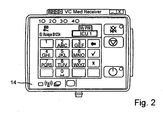
- FIG. 2 shows the Rename mode, in which by pressing the corresponding keys, the identification word ICU1 in any other identification word, for example, OP1, can be changed. Accordingly, the identification words Patient1 and ICU2 can be changed by pressing the respective Rename button 24. If the identification word or My PIN is considered correct, the OK key 26 can be actuated. The touchscreens 20 then switch to the in FIG. 3 shown mode. In this mode, the transmitting unit 12 sends a registration request to the receiving units 14, 16 and waits a receiving unit-side confirmation for the registration of the transmitting unit 12 and thus to establish a radio link.
- the transmitting unit 12 sends a registration request to the receiving units 14, 16 and waits a receiving unit-side confirmation for the registration of the transmitting unit 12 and thus to establish a radio link.
- the receiving units 14 and 16 it is indicated which transmitting units 12 are present in the radio range and have sent a corresponding registration request.
- the freely selected code word is displayed by the transmitting units, as well as, behind it, in parentheses, the associated identification code.
- the transmission units present in the radio range consequently send their identification code together with the identification word to the receiving units 14, 16.
- the desired transmitter unit To set up a radio connection transmitting the measurement data, the desired transmitter unit must be confirmed on the receiver side. This is done by selecting the respective transmission unit by pressing the selection keys 28, 30. If the desired transmission unit is selected, this is confirmed by pressing the confirmation key 32.
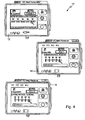
- FIG. 4 shows the display of the respective touchscreen during connection setup.
- FIG. 5 the mode of operation is shown according to the invented structure; The so-called pairing was completed successfully.
- the transmitting unit 12 that is, Patient1
- the receiving unit 14 that is, with ICU1.
- This is permanently displayed on the touch screen 20 of the transmitting unit.
- FIG. 5 is therefore only a connection between the transmitting unit 12 and the receiving unit 14 produced; a connection to the receiving unit 16 is according to FIG. 5 Not.
- the transmitting unit 12 and the receiving units 14 and 16 comprise displays 34 and 36, which are formed separately from the touchscreen and which indicate whether there is only one connection to another unit or whether there is a connection to a plurality of further units. If there is only one connection to a unit, then the display 34 lights up. If there is a connection with several other units, the display 36 lights up. Because in FIG. 5 a connection of the transmitting unit 12 with only one receiving unit 14, consequently, the display 34 lights up. In the event that there would be a further connection to the transmitting unit 12, then the display 34 would go out and the display 36 on the transmitting unit 12 will light up. In addition, the identification word together with the identification code of the further receiving unit 16 would be displayed on the display 20 of the transmitting unit 12.
- this receiver will be permanently displayed on the transmitter side with an existing radio connection. If there is already a connection to an existing receiver in the operating room in the preparation room, this would also be displayed on the transmitter side. Should a further receiving unit also be present in a recovery room, this would also be displayed on the transmitter side if there is a radio connection. Consequently, it can always be determined on the transmitter side whether and with which receiver units a connection is present. On the other hand, it can be determined at the respective receiving unit to which patient a connection is present and from which patient corresponding measurement data are displayed graphically.
- the transmitting unit 12 leaves the radio range of the receiving unit 14, this is shown on the transmitting unit 12 as well as on the receiving unit 14, as in FIG FIG. 6 shown. Since there is no longer any radio connection, the transmitting unit 12 falls back into the interrogation mode and searches for available reception units in the radio area. Accordingly, it is displayed on the receiving unit 14 which transmission units are still present in the radio range. To restore a connection, the respective transmitting unit or the associated patient must be newly registered, ie select and the selection must be confirmed.
- connection is automatically restored without making a new application as soon as that transmission unit that had previously left the reception area of the associated receiver re-enters the reception area. Measurement data are then automatically transferred again and displayed on the monitor. The identification code of the transmitting unit is not deleted in the associated data memory of the receiver.
- a warning can additionally be output by means of an optical and / or acoustic signal at the receiving unit, connected to a display on the display 20 of the receiving unit 14, 16, that the radio connection previously torn off over a period of time has been resumed.
- the user With the restoration of the radio connection, the user is asked in particular at the receiving unit, whether the existing radio link should continue to be maintained or whether it should be canceled. The user is thus given the choice to maintain the connection or abort.
- the respective radio partner of the transmitting and receiving unit, or their identification code and / or identification word can before, during and after this request permanently to the respective transmitting unit and at the one or more Receive unit (s) remain displayed. After answering the request, it will expire; However, it can remain stored in a history menu of the receiving and transmitting unit for a period of time to be defined.
- a reset button 40 is provided on the units.
- the displays 34 and 36 is thus permanently displayed whether a radio link between one or more receiving units 14, 16 is provided. Furthermore, if there is a radio connection, the transmission unit 12 is displayed on the touch screen, with which or with which reception units 14, 16 there is a radio connection. On the side of the receiving units 14, 16 is displayed on the respective touch screen, with which transmitting unit 12, a radio link is present.
- the transmitting unit 12 is preferably operated with a replaceable battery.
- another internal battery is provided and designed so that they can supply the transmitting unit 12 for a sufficient amount of power until the battery replacement is completed, for example one to two minutes.
- the internal battery can be recharged, in particular via the replaceable battery or by means of an external power supply.
- the replaceable battery is preferably a rechargeable battery.
- a charging station can be provided, in particular at the receiving units 14, 16, so that a charged battery is always available.
- the receiving units 14, 16 themselves are preferably operated with energy from a power grid, since the receiving units regularly a fixed location in the area of a monitor where an external power supply is guaranteed.
- the receiving units 14, 16 may also be designed to be mobile.
- the receiving units, according to the transmitting units preferably a replaceable and an internal battery.
Landscapes
- Health & Medical Sciences (AREA)
- Engineering & Computer Science (AREA)
- Biomedical Technology (AREA)
- Life Sciences & Earth Sciences (AREA)
- General Health & Medical Sciences (AREA)
- Medical Informatics (AREA)
- Public Health (AREA)
- Surgery (AREA)
- General Business, Economics & Management (AREA)
- Primary Health Care (AREA)
- Molecular Biology (AREA)
- Heart & Thoracic Surgery (AREA)
- Animal Behavior & Ethology (AREA)
- Physics & Mathematics (AREA)
- Epidemiology (AREA)
- Veterinary Medicine (AREA)
- Business, Economics & Management (AREA)
- Pathology (AREA)
- Biophysics (AREA)
- Computer Networks & Wireless Communication (AREA)
- Nuclear Medicine, Radiotherapy & Molecular Imaging (AREA)
- Optics & Photonics (AREA)
- Radiology & Medical Imaging (AREA)
- Physiology (AREA)
- Dentistry (AREA)
- Oral & Maxillofacial Surgery (AREA)
- Computing Systems (AREA)
- Signal Processing (AREA)
- Measuring And Recording Apparatus For Diagnosis (AREA)
Claims (16)
- Procédé pour faire fonctionner un système de surveillance de patient (10) comprenant une unité émettrice (12) qui émet, via une liaison radio, des données de mesure prélevées sur un patient, et plusieurs unités de réception (14, 16) qui reçoivent les données de mesure émises par l'unité émettrice (12), un code d'identification (ID) univoque étant associé à l'unité émettrice (12) et à chacune des unités réceptrices (14, 16) et une liaison radio pour la transmission de données de mesure de l'unité émettrice (12) vers la pluralité d'unités réceptrices (14, 16) ne pouvant être établie que lorsque l'unité émettrice (12) a été connectée à l'unité réceptrice (14, 16) en utilisant son code d'identification (ID), une liaison radio transmettant des données de mesure pouvant être établie entre l'unité émettrice (12) et plusieurs unités réceptrices (14, 16), caractérisé en ce que s'affiche de manière durable sur l'unité émettrice (12) la ou les unités réceptrices (14, 16) avec laquelle ou lesquelles il existe une liaison radio transmettant des données de mesure.
- Procédé selon la revendication 1, caractérisé en ce qu'il est affiché de manière durable non seulement sur l'unité émettrice (12) mais aussi sur l'unité réceptrice (14, 16) s'il existe une liaison radio avec une unité émettrice (12) et/ou avec quelle unité émettrice (12) il existe une liaison radio.
- Procédé selon la revendication 1 ou la revendication 2, caractérisé en ce que l'existence d'une liaison radio n'est plus affichée sur l'unité émettrice (12) et/ou l'unité réceptrice (14, 16) lorsqu'une déconnexion manuelle de l'unité réceptrice considérée (14, 16) est réalisée ou lorsqu'il n'existe plus de liaison radio avec ladite unité réceptrice (14, 16).
- Procédé selon la revendication 1, 2 ou 3, caractérisé en ce que, pour établir la liaison radio, lorsque l'une au moins des unités réceptrices (14, 16) se trouve dans la zone de portée radio de l'unité émettrice (12), ladite unité émettrice (12) adresse une demande de connexion à telle ou telle unité réceptrice (14, 16) en utilisant son code d'identification (ID), et la connexion de l'unité émettrice (12) à telle ou telle unité réceptrice (14, 16) ainsi que l'établissement d'une liaison radio pour la transmission des données de mesure n'ont lieu que lorsque la demande de connexion adressée à l'unité réceptrice (14, 16) est validée.
- Procédé selon la revendication 4, caractérisé en ce qu'il est affiché sur l'unité réceptrice (14, 16) s'il existe une demande de connexion et en provenance de quelle unité émettrice (12).
- Procédé selon la revendication 4 ou la revendication 5, caractérisé en ce que, suite à la demande de connexion, le code d'identification (ID) de l'unité émettrice (12) s'affiche sur l'unité réceptrice (14, 16) concernée et en ce qu'une connexion se fait par sélection et confirmation de la sélection, sans qu'il soit besoin de saisir manuellement le code d'identification (ID) en tant que tel, en particulier au moyen d'un clavier.
- Procédé selon l'une au moins des revendications précédentes, caractérisé en ce que l'unité émettrice (12) émet un signal lorsqu'il n'existe plus, pendant une durée prédéfinissable, de liaison radio vers au moins une unité réceptrice (14, 16).
- Procédé selon l'une au moins des revendications précédentes, caractérisé en ce que même après une interruption de quelques minutes de la liaison radio entre l'unité émettrice et une unité réceptrice, une liaison radio est automatiquement rétablie entre l'unité émettrice et l'unité réceptrice sans qu'il soit besoin d'indiquer à nouveau à l'unité réceptrice le code d'identification de l'unité émettrice.
- Procédé selon la revendication 8, caractérisé en ce que le rétablissement de la liaison radio s'affiche sur l'unité émettrice et/ou l'unité réceptrice.
- Procédé selon la revendication 8 ou la revendication 9, caractérisé en ce que lors de ou après le rétablissement de la liaison radio, il est demandé si la liaison radio existante doit être maintenue ou si elle doit être interrompue.
- Procédé selon l'une au moins des revendications précédentes, caractérisé en ce que, sur l'unité émettrice (12), un terme d'identification défini par l'utilisateur (PIN) peut être affecté au code d'identification (ID) de l'unité émettrice (12) et/ou en ce que, sur l'unité réceptrice (14, 16), un terme d'identification défini par l'utilisateur (PIN) peut être affecté au code d'identification (ID) de l'unité réceptrice pour l'utiliser en lieu et place du code d'identification (ID) considéré.
- Procédé selon l'une au moins des revendications précédentes, caractérisé en ce que l'on enregistre dans l'unité émettrice (12) et/ou les différentes unités réceptrices (14, 16) quand et combien de temps une liaison radio a été établie avec quelle unité réceptrice (14, 16) et/ou unité émettrice (12).
- Système de surveillance de patient (10) comprenant une unité émettrice (12) qui émet, via une liaison radio, des données de mesure prélevées sur un patient, et plusieurs unités de réception (14, 16) qui reçoivent les données de mesure émises par l'unité émettrice, destiné à mettre en oeuvre le procédé selon l'une au moins des revendications précédentes, des moyens d'affichage (20, 34, 36) étant prévus sur l'unité émettrice (12) pour afficher de manière durable avec laquelle des unités réceptrices (14, 16) il existe une liaison radio.
- Système selon la revendication 13, caractérisé en ce que des moyens d'affichage (20, 34, 36) sont prévus sur l'unité réceptrice (14, 16) pour afficher de manière durable s'il existe une liaison radio avec l'unité émettrice (12).
- Système selon l'une au moins des revendications 13 et 14, caractérisé en ce que l'unité émettrice (12) et/ou l'unité réceptrice (14, 16) présentent une batterie remplaçable destinée à alimenter en énergie l'unité émettrice et en ce que l'unité émettrice (12) et/ou l'unité réceptrice (14, 16) comprennent une batterie interne qui alimente respectivement en énergie l'unité émettrice et/ou l'unité réceptrice (14, 16) lorsque l'on ôte la batterie remplaçable.
- Système selon la revendication 15, caractérisé en ce qu'une station de charge est prévue sur l'unité réceptrice (14, 16) et/ou l'unité émettrice (12) pour charger respectivement la batterie remplaçable de l'unité émettrice (12) et/ou de l'unité réceptrice (14, 16).
Priority Applications (2)
| Application Number | Priority Date | Filing Date | Title |
|---|---|---|---|
| SI200930592T SI2339954T1 (sl) | 2008-08-06 | 2009-08-05 | Postopek za delovanje sistema za spremljanje pacientov in sistem za spremljanje pacientov |
| PL09777661T PL2339954T3 (pl) | 2008-08-06 | 2009-08-05 | Sposób operowania systemem monitorowania pacjenta i system monitorowania pacjenta |
Applications Claiming Priority (2)
| Application Number | Priority Date | Filing Date | Title |
|---|---|---|---|
| DE200810036820 DE102008036820A1 (de) | 2008-08-06 | 2008-08-06 | Verfahren zum Betreiben eines Patientenüberwachungssystems und Patientenüberwachungssystem |
| PCT/EP2009/005658 WO2010015390A1 (fr) | 2008-08-06 | 2009-08-05 | Procédé pour faire fonctionner un système de surveillance de patient et système de surveillance de patient |
Publications (2)
| Publication Number | Publication Date |
|---|---|
| EP2339954A1 EP2339954A1 (fr) | 2011-07-06 |
| EP2339954B1 true EP2339954B1 (fr) | 2013-04-24 |
Family
ID=41171175
Family Applications (1)
| Application Number | Title | Priority Date | Filing Date |
|---|---|---|---|
| EP20090777661 Revoked EP2339954B1 (fr) | 2008-08-06 | 2009-08-05 | Procédé pour faire fonctionner un système de surveillance de patient et système de surveillance de patient |
Country Status (6)
| Country | Link |
|---|---|
| EP (1) | EP2339954B1 (fr) |
| DE (1) | DE102008036820A1 (fr) |
| ES (1) | ES2422264T3 (fr) |
| PL (1) | PL2339954T3 (fr) |
| SI (1) | SI2339954T1 (fr) |
| WO (1) | WO2010015390A1 (fr) |
Families Citing this family (1)
| Publication number | Priority date | Publication date | Assignee | Title |
|---|---|---|---|---|
| USD970017S1 (en) | 2020-08-25 | 2022-11-15 | Coloplast A/S | Ostomy appliance monitor |
Family Cites Families (6)
| Publication number | Priority date | Publication date | Assignee | Title |
|---|---|---|---|---|
| EP0602459B1 (fr) * | 1992-12-16 | 1999-11-03 | Siemens Medical Systems, Inc. | Système de surveillance des données et du lieu où se trouve le patient |
| ES2362414T3 (es) | 2000-05-19 | 2011-07-05 | Welch Allyn Protocol Inc | Sistema de monitorización de pacientes. |
| DE10221179A1 (de) | 2002-05-13 | 2003-12-18 | Siemens Ag | Medizinisches Diagnose- und/oder Therapiegerät mit Verfahren zur fehlergeschützten Kommunikation mit diesem Gerät |
| DE102004012042B4 (de) | 2004-03-10 | 2008-04-10 | Smiths Medical Deutschland Gmbh | Patientenüberwachungsvorrichtung |
| DE202006014172U1 (de) * | 2006-09-12 | 2006-12-21 | Smiths Medical Deutschland Gmbh | Patientenüberwachungsvorrichtung |
| DE202006014171U1 (de) | 2006-09-12 | 2007-01-04 | Smiths Medical Deutschland Gmbh | Patientenüberwachungsvorrichtung |
-
2008
- 2008-08-06 DE DE200810036820 patent/DE102008036820A1/de not_active Withdrawn
-
2009
- 2009-08-05 PL PL09777661T patent/PL2339954T3/pl unknown
- 2009-08-05 SI SI200930592T patent/SI2339954T1/sl unknown
- 2009-08-05 WO PCT/EP2009/005658 patent/WO2010015390A1/fr not_active Ceased
- 2009-08-05 ES ES09777661T patent/ES2422264T3/es active Active
- 2009-08-05 EP EP20090777661 patent/EP2339954B1/fr not_active Revoked
Also Published As
| Publication number | Publication date |
|---|---|
| EP2339954A1 (fr) | 2011-07-06 |
| PL2339954T3 (pl) | 2013-09-30 |
| DE102008036820A1 (de) | 2010-02-11 |
| WO2010015390A1 (fr) | 2010-02-11 |
| ES2422264T3 (es) | 2013-09-10 |
| SI2339954T1 (sl) | 2013-08-30 |
Similar Documents
| Publication | Publication Date | Title |
|---|---|---|
| DE10040521C2 (de) | Fahrzeug, insbesondere Rollstuhl | |
| DE102004012042B4 (de) | Patientenüberwachungsvorrichtung | |
| DE102010006845B4 (de) | Medizintechnische Vorrichtung mit kabellosem Fussschaltgerät | |
| DE69731901T2 (de) | Tragbare telemedizinische vorrichtung | |
| EP2139384A2 (fr) | Ensemble constitué d'unités de traitement médicales et de périphériques ainsi que périphérique et unité de traitement à utiliser dans un tel système | |
| DE112020001196T5 (de) | Batterieüberwachungsgerät | |
| EP2339954B1 (fr) | Procédé pour faire fonctionner un système de surveillance de patient et système de surveillance de patient | |
| EP2881018B2 (fr) | Dispositif de préparation automatisée d'une boisson chaude | |
| DE102006012471A1 (de) | Verfahren und System zur drahtlosen Übertragung von Steuerungsbefehlen für eine Steuerung eines Hebezeugs | |
| EP3433776B1 (fr) | Commande à distance des messages d'un appareil de dialyse | |
| DE10048338A1 (de) | Fernbedienung für ein Hörhilfegerät | |
| DE10046963C1 (de) | Fahrzeug, insbesondere Rollstuhl | |
| DE10221179A1 (de) | Medizinisches Diagnose- und/oder Therapiegerät mit Verfahren zur fehlergeschützten Kommunikation mit diesem Gerät | |
| DE10236198A1 (de) | Programmierbare Gegenstandsbefestigung zur Gewinnung von Informationen über die Nutzung medizinischer Ausrüstung | |
| DE10008411A1 (de) | Verfahren zur Aufnahme und Übertragung eines mehrkanaligen EKG und Anordnung als tragbarer Recorder zur Durchführung des Verfahrens | |
| DE10250370A1 (de) | Fernsteuerung für Fernseher oder Videorekorder, die das Körperfett messen kann, sowie Körperfettmessgerät | |
| WO2020007577A1 (fr) | Procédé de fonctionnement d'un dispositif médical et dispositif médical fonctionnant selon ce procédé | |
| DE102018204210B4 (de) | Drahtloskomponente einer Brandschutz-Feststellanlage und Betriebsverfahren | |
| WO2008113513A1 (fr) | Système de commande d'appareils médicaux, notamment d'un poste de travail dentaire | |
| DE202011110315U1 (de) | System zur Aufnahme, Auswertung, Speicherung, Aufbereitung, Übertragung und/oder Darstellung von Vitalfunktionswerten | |
| DE102017217128B4 (de) | Erweiterungseinheit für ein mobiles Endgerät | |
| EP1544827A2 (fr) | Dispositif et méthode pour la configuration et l'activation d'une télécommande | |
| DE10032943C2 (de) | Modulnetzwerk | |
| EP4475138A1 (fr) | Appareil médical avec fonction de station de travail dans un système de traitement de données | |
| DE102024003360A1 (de) | Arbeitsgerät für den Einsatz im Sanitärbereich, insbesondere Press-werkzeug für Rohre und dgl., sowie Verfahren zum Betrieb des Arbeitsgerätes |
Legal Events
| Date | Code | Title | Description |
|---|---|---|---|
| PUAI | Public reference made under article 153(3) epc to a published international application that has entered the european phase |
Free format text: ORIGINAL CODE: 0009012 |
|
| 17P | Request for examination filed |
Effective date: 20110203 |
|
| AK | Designated contracting states |
Kind code of ref document: A1 Designated state(s): AT BE BG CH CY CZ DE DK EE ES FI FR GB GR HR HU IE IS IT LI LT LU LV MC MK MT NL NO PL PT RO SE SI SK SM TR |
|
| AX | Request for extension of the european patent |
Extension state: AL BA RS |
|
| DAX | Request for extension of the european patent (deleted) | ||
| 17Q | First examination report despatched |
Effective date: 20120118 |
|
| GRAP | Despatch of communication of intention to grant a patent |
Free format text: ORIGINAL CODE: EPIDOSNIGR1 |
|
| GRAS | Grant fee paid |
Free format text: ORIGINAL CODE: EPIDOSNIGR3 |
|
| GRAA | (expected) grant |
Free format text: ORIGINAL CODE: 0009210 |
|
| AK | Designated contracting states |
Kind code of ref document: B1 Designated state(s): AT BE BG CH CY CZ DE DK EE ES FI FR GB GR HR HU IE IS IT LI LT LU LV MC MK MT NL NO PL PT RO SE SI SK SM TR |
|
| REG | Reference to a national code |
Ref country code: GB Ref legal event code: FG4D Free format text: NOT ENGLISH |
|
| REG | Reference to a national code |
Ref country code: CH Ref legal event code: EP |
|
| REG | Reference to a national code |
Ref country code: AT Ref legal event code: REF Ref document number: 608070 Country of ref document: AT Kind code of ref document: T Effective date: 20130515 |
|
| REG | Reference to a national code |
Ref country code: IE Ref legal event code: FG4D Free format text: LANGUAGE OF EP DOCUMENT: GERMAN |
|
| REG | Reference to a national code |
Ref country code: DE Ref legal event code: R096 Ref document number: 502009006962 Country of ref document: DE Effective date: 20130620 |
|
| REG | Reference to a national code |
Ref country code: CH Ref legal event code: NV Representative=s name: DREISS PATENTANWAELTE, DE |
|
| REG | Reference to a national code |
Ref country code: ES Ref legal event code: FG2A Ref document number: 2422264 Country of ref document: ES Kind code of ref document: T3 Effective date: 20130910 |
|
| REG | Reference to a national code |
Ref country code: NL Ref legal event code: T3 |
|
| REG | Reference to a national code |
Ref country code: LT Ref legal event code: MG4D |
|
| REG | Reference to a national code |
Ref country code: PL Ref legal event code: T3 |
|
| PG25 | Lapsed in a contracting state [announced via postgrant information from national office to epo] |
Ref country code: SE Free format text: LAPSE BECAUSE OF FAILURE TO SUBMIT A TRANSLATION OF THE DESCRIPTION OR TO PAY THE FEE WITHIN THE PRESCRIBED TIME-LIMIT Effective date: 20130424 Ref country code: FI Free format text: LAPSE BECAUSE OF FAILURE TO SUBMIT A TRANSLATION OF THE DESCRIPTION OR TO PAY THE FEE WITHIN THE PRESCRIBED TIME-LIMIT Effective date: 20130424 Ref country code: LT Free format text: LAPSE BECAUSE OF FAILURE TO SUBMIT A TRANSLATION OF THE DESCRIPTION OR TO PAY THE FEE WITHIN THE PRESCRIBED TIME-LIMIT Effective date: 20130424 Ref country code: NO Free format text: LAPSE BECAUSE OF FAILURE TO SUBMIT A TRANSLATION OF THE DESCRIPTION OR TO PAY THE FEE WITHIN THE PRESCRIBED TIME-LIMIT Effective date: 20130724 Ref country code: GR Free format text: LAPSE BECAUSE OF FAILURE TO SUBMIT A TRANSLATION OF THE DESCRIPTION OR TO PAY THE FEE WITHIN THE PRESCRIBED TIME-LIMIT Effective date: 20130725 Ref country code: IS Free format text: LAPSE BECAUSE OF FAILURE TO SUBMIT A TRANSLATION OF THE DESCRIPTION OR TO PAY THE FEE WITHIN THE PRESCRIBED TIME-LIMIT Effective date: 20130824 Ref country code: PT Free format text: LAPSE BECAUSE OF FAILURE TO SUBMIT A TRANSLATION OF THE DESCRIPTION OR TO PAY THE FEE WITHIN THE PRESCRIBED TIME-LIMIT Effective date: 20130826 |
|
| PG25 | Lapsed in a contracting state [announced via postgrant information from national office to epo] |
Ref country code: LV Free format text: LAPSE BECAUSE OF FAILURE TO SUBMIT A TRANSLATION OF THE DESCRIPTION OR TO PAY THE FEE WITHIN THE PRESCRIBED TIME-LIMIT Effective date: 20130424 Ref country code: HR Free format text: LAPSE BECAUSE OF FAILURE TO SUBMIT A TRANSLATION OF THE DESCRIPTION OR TO PAY THE FEE WITHIN THE PRESCRIBED TIME-LIMIT Effective date: 20130424 Ref country code: BG Free format text: LAPSE BECAUSE OF FAILURE TO SUBMIT A TRANSLATION OF THE DESCRIPTION OR TO PAY THE FEE WITHIN THE PRESCRIBED TIME-LIMIT Effective date: 20130724 Ref country code: CY Free format text: LAPSE BECAUSE OF FAILURE TO SUBMIT A TRANSLATION OF THE DESCRIPTION OR TO PAY THE FEE WITHIN THE PRESCRIBED TIME-LIMIT Effective date: 20130424 |
|
| PG25 | Lapsed in a contracting state [announced via postgrant information from national office to epo] |
Ref country code: EE Free format text: LAPSE BECAUSE OF FAILURE TO SUBMIT A TRANSLATION OF THE DESCRIPTION OR TO PAY THE FEE WITHIN THE PRESCRIBED TIME-LIMIT Effective date: 20130424 Ref country code: DK Free format text: LAPSE BECAUSE OF FAILURE TO SUBMIT A TRANSLATION OF THE DESCRIPTION OR TO PAY THE FEE WITHIN THE PRESCRIBED TIME-LIMIT Effective date: 20130424 Ref country code: SK Free format text: LAPSE BECAUSE OF FAILURE TO SUBMIT A TRANSLATION OF THE DESCRIPTION OR TO PAY THE FEE WITHIN THE PRESCRIBED TIME-LIMIT Effective date: 20130424 Ref country code: CZ Free format text: LAPSE BECAUSE OF FAILURE TO SUBMIT A TRANSLATION OF THE DESCRIPTION OR TO PAY THE FEE WITHIN THE PRESCRIBED TIME-LIMIT Effective date: 20130424 |
|
| PLBI | Opposition filed |
Free format text: ORIGINAL CODE: 0009260 |
|
| PG25 | Lapsed in a contracting state [announced via postgrant information from national office to epo] |
Ref country code: RO Free format text: LAPSE BECAUSE OF FAILURE TO SUBMIT A TRANSLATION OF THE DESCRIPTION OR TO PAY THE FEE WITHIN THE PRESCRIBED TIME-LIMIT Effective date: 20130424 |
|
| PLAX | Notice of opposition and request to file observation + time limit sent |
Free format text: ORIGINAL CODE: EPIDOSNOBS2 |
|
| 26 | Opposition filed |
Opponent name: FRESENIUS MEDICAL CARE DEUTSCHLAND GMBH Effective date: 20140123 |
|
| REG | Reference to a national code |
Ref country code: CH Ref legal event code: PFA Owner name: BECK, BERND, SI Free format text: FORMER OWNER: BECK, BERND, SI |
|
| REG | Reference to a national code |
Ref country code: DE Ref legal event code: R026 Ref document number: 502009006962 Country of ref document: DE Effective date: 20140123 |
|
| PG25 | Lapsed in a contracting state [announced via postgrant information from national office to epo] |
Ref country code: MC Free format text: LAPSE BECAUSE OF FAILURE TO SUBMIT A TRANSLATION OF THE DESCRIPTION OR TO PAY THE FEE WITHIN THE PRESCRIBED TIME-LIMIT Effective date: 20130424 |
|
| REG | Reference to a national code |
Ref country code: IE Ref legal event code: MM4A |
|
| PLAF | Information modified related to communication of a notice of opposition and request to file observations + time limit |
Free format text: ORIGINAL CODE: EPIDOSCOBS2 |
|
| PG25 | Lapsed in a contracting state [announced via postgrant information from national office to epo] |
Ref country code: IE Free format text: LAPSE BECAUSE OF NON-PAYMENT OF DUE FEES Effective date: 20130805 |
|
| PLBB | Reply of patent proprietor to notice(s) of opposition received |
Free format text: ORIGINAL CODE: EPIDOSNOBS3 |
|
| REG | Reference to a national code |
Ref country code: CH Ref legal event code: PCAR Free format text: NEW ADDRESS: FRIEDERICHSTR. 6, 70174 STUTTGART (DE) |
|
| REG | Reference to a national code |
Ref country code: CH Ref legal event code: PCAR Free format text: NEW ADDRESS: FRIEDRICHSTR. 6, 70174 STUTTGART (DE) |
|
| PG25 | Lapsed in a contracting state [announced via postgrant information from national office to epo] |
Ref country code: SM Free format text: LAPSE BECAUSE OF FAILURE TO SUBMIT A TRANSLATION OF THE DESCRIPTION OR TO PAY THE FEE WITHIN THE PRESCRIBED TIME-LIMIT Effective date: 20130424 |
|
| PG25 | Lapsed in a contracting state [announced via postgrant information from national office to epo] |
Ref country code: MT Free format text: LAPSE BECAUSE OF FAILURE TO SUBMIT A TRANSLATION OF THE DESCRIPTION OR TO PAY THE FEE WITHIN THE PRESCRIBED TIME-LIMIT Effective date: 20130424 |
|
| PG25 | Lapsed in a contracting state [announced via postgrant information from national office to epo] |
Ref country code: HU Free format text: LAPSE BECAUSE OF FAILURE TO SUBMIT A TRANSLATION OF THE DESCRIPTION OR TO PAY THE FEE WITHIN THE PRESCRIBED TIME-LIMIT; INVALID AB INITIO Effective date: 20090805 Ref country code: LU Free format text: LAPSE BECAUSE OF NON-PAYMENT OF DUE FEES Effective date: 20130805 Ref country code: MK Free format text: LAPSE BECAUSE OF FAILURE TO SUBMIT A TRANSLATION OF THE DESCRIPTION OR TO PAY THE FEE WITHIN THE PRESCRIBED TIME-LIMIT Effective date: 20130424 |
|
| REG | Reference to a national code |
Ref country code: FR Ref legal event code: PLFP Year of fee payment: 7 |
|
| PGFP | Annual fee paid to national office [announced via postgrant information from national office to epo] |
Ref country code: NL Payment date: 20150824 Year of fee payment: 7 |
|
| REG | Reference to a national code |
Ref country code: DE Ref legal event code: R103 Ref document number: 502009006962 Country of ref document: DE Ref country code: DE Ref legal event code: R064 Ref document number: 502009006962 Country of ref document: DE |
|
| PGFP | Annual fee paid to national office [announced via postgrant information from national office to epo] |
Ref country code: ES Payment date: 20150825 Year of fee payment: 7 Ref country code: GB Payment date: 20150811 Year of fee payment: 7 Ref country code: CH Payment date: 20150824 Year of fee payment: 7 |
|
| PGFP | Annual fee paid to national office [announced via postgrant information from national office to epo] |
Ref country code: PL Payment date: 20150727 Year of fee payment: 7 Ref country code: BE Payment date: 20150820 Year of fee payment: 7 Ref country code: AT Payment date: 20150820 Year of fee payment: 7 Ref country code: SI Payment date: 20150728 Year of fee payment: 7 Ref country code: TR Payment date: 20150728 Year of fee payment: 7 Ref country code: FR Payment date: 20150824 Year of fee payment: 7 |
|
| RDAF | Communication despatched that patent is revoked |
Free format text: ORIGINAL CODE: EPIDOSNREV1 |
|
| PGFP | Annual fee paid to national office [announced via postgrant information from national office to epo] |
Ref country code: IT Payment date: 20150827 Year of fee payment: 7 |
|
| PGFP | Annual fee paid to national office [announced via postgrant information from national office to epo] |
Ref country code: DE Payment date: 20151019 Year of fee payment: 7 |
|
| RDAG | Patent revoked |
Free format text: ORIGINAL CODE: 0009271 |
|
| STAA | Information on the status of an ep patent application or granted ep patent |
Free format text: STATUS: PATENT REVOKED |
|
| REG | Reference to a national code |
Ref country code: CH Ref legal event code: PLX |
|
| 27W | Patent revoked |
Effective date: 20151029 |
|
| GBPR | Gb: patent revoked under art. 102 of the ep convention designating the uk as contracting state |
Effective date: 20151029 |
|
| PG25 | Lapsed in a contracting state [announced via postgrant information from national office to epo] |
Ref country code: CH Free format text: LAPSE BECAUSE OF THE APPLICANT RENOUNCES Effective date: 20130424 Ref country code: LI Free format text: LAPSE BECAUSE OF THE APPLICANT RENOUNCES Effective date: 20130424 |
|
| REG | Reference to a national code |
Ref country code: AT Ref legal event code: MA03 Ref document number: 608070 Country of ref document: AT Kind code of ref document: T Effective date: 20151029 |
|
| REG | Reference to a national code |
Ref country code: SI Ref legal event code: KO00 Effective date: 20170418 |