EP2340084B1 - Systèmes et procédés pour collecter des informations d'événement de patient - Google Patents
Systèmes et procédés pour collecter des informations d'événement de patient Download PDFInfo
- Publication number
- EP2340084B1 EP2340084B1 EP09790539.2A EP09790539A EP2340084B1 EP 2340084 B1 EP2340084 B1 EP 2340084B1 EP 09790539 A EP09790539 A EP 09790539A EP 2340084 B1 EP2340084 B1 EP 2340084B1
- Authority
- EP
- European Patent Office
- Prior art keywords
- crm
- reason
- transmission session
- patient
- user
- Prior art date
- Legal status (The legal status is an assumption and is not a legal conclusion. Google has not performed a legal analysis and makes no representation as to the accuracy of the status listed.)
- Not-in-force
Links
- 238000000034 method Methods 0.000 title claims description 27
- 230000005540 biological transmission Effects 0.000 claims description 75
- 238000007726 management method Methods 0.000 claims description 43
- 238000004891 communication Methods 0.000 claims description 25
- 230000000747 cardiac effect Effects 0.000 claims description 16
- 230000003466 anti-cipated effect Effects 0.000 claims description 13
- 230000033764 rhythmic process Effects 0.000 claims description 11
- 230000035939 shock Effects 0.000 claims description 9
- 230000000694 effects Effects 0.000 claims description 7
- 230000000977 initiatory effect Effects 0.000 claims description 7
- 238000012552 review Methods 0.000 claims description 6
- 206010019280 Heart failures Diseases 0.000 claims description 5
- 230000008672 reprogramming Effects 0.000 claims description 5
- 238000001514 detection method Methods 0.000 claims description 2
- 238000012544 monitoring process Methods 0.000 description 13
- 238000002560 therapeutic procedure Methods 0.000 description 7
- 230000004044 response Effects 0.000 description 6
- 238000010586 diagram Methods 0.000 description 4
- 238000012545 processing Methods 0.000 description 4
- 230000000638 stimulation Effects 0.000 description 4
- 230000001746 atrial effect Effects 0.000 description 3
- 230000008859 change Effects 0.000 description 3
- 238000013500 data storage Methods 0.000 description 3
- 238000001356 surgical procedure Methods 0.000 description 3
- 230000002861 ventricular Effects 0.000 description 3
- 206010020772 Hypertension Diseases 0.000 description 2
- 238000013461 design Methods 0.000 description 2
- 238000003384 imaging method Methods 0.000 description 2
- 230000001939 inductive effect Effects 0.000 description 2
- 230000028161 membrane depolarization Effects 0.000 description 2
- 238000012986 modification Methods 0.000 description 2
- 230000004048 modification Effects 0.000 description 2
- 208000024891 symptom Diseases 0.000 description 2
- 230000000007 visual effect Effects 0.000 description 2
- 208000033748 Device issues Diseases 0.000 description 1
- 208000000059 Dyspnea Diseases 0.000 description 1
- 206010013975 Dyspnoeas Diseases 0.000 description 1
- 206010040639 Sick sinus syndrome Diseases 0.000 description 1
- 208000001871 Tachycardia Diseases 0.000 description 1
- 230000006978 adaptation Effects 0.000 description 1
- 230000002457 bidirectional effect Effects 0.000 description 1
- 230000036772 blood pressure Effects 0.000 description 1
- 238000002591 computed tomography Methods 0.000 description 1
- 238000012790 confirmation Methods 0.000 description 1
- 230000036541 health Effects 0.000 description 1
- 210000005003 heart tissue Anatomy 0.000 description 1
- 230000001771 impaired effect Effects 0.000 description 1
- 238000002513 implantation Methods 0.000 description 1
- 238000012423 maintenance Methods 0.000 description 1
- 230000003287 optical effect Effects 0.000 description 1
- 230000008569 process Effects 0.000 description 1
- 230000029058 respiratory gaseous exchange Effects 0.000 description 1
- 208000013220 shortness of breath Diseases 0.000 description 1
- 230000006794 tachycardia Effects 0.000 description 1
- 208000003663 ventricular fibrillation Diseases 0.000 description 1
- 206010047302 ventricular tachycardia Diseases 0.000 description 1
Images





Classifications
-
- A—HUMAN NECESSITIES
- A61—MEDICAL OR VETERINARY SCIENCE; HYGIENE
- A61N—ELECTROTHERAPY; MAGNETOTHERAPY; RADIATION THERAPY; ULTRASOUND THERAPY
- A61N1/00—Electrotherapy; Circuits therefor
- A61N1/18—Applying electric currents by contact electrodes
- A61N1/32—Applying electric currents by contact electrodes alternating or intermittent currents
- A61N1/36—Applying electric currents by contact electrodes alternating or intermittent currents for stimulation
- A61N1/372—Arrangements in connection with the implantation of stimulators
- A61N1/37211—Means for communicating with stimulators
- A61N1/37235—Aspects of the external programmer
- A61N1/37247—User interfaces, e.g. input or presentation means
-
- G—PHYSICS
- G16—INFORMATION AND COMMUNICATION TECHNOLOGY [ICT] SPECIALLY ADAPTED FOR SPECIFIC APPLICATION FIELDS
- G16H—HEALTHCARE INFORMATICS, i.e. INFORMATION AND COMMUNICATION TECHNOLOGY [ICT] SPECIALLY ADAPTED FOR THE HANDLING OR PROCESSING OF MEDICAL OR HEALTHCARE DATA
- G16H40/00—ICT specially adapted for the management or administration of healthcare resources or facilities; ICT specially adapted for the management or operation of medical equipment or devices
- G16H40/60—ICT specially adapted for the management or administration of healthcare resources or facilities; ICT specially adapted for the management or operation of medical equipment or devices for the operation of medical equipment or devices
- G16H40/63—ICT specially adapted for the management or administration of healthcare resources or facilities; ICT specially adapted for the management or operation of medical equipment or devices for the operation of medical equipment or devices for local operation
-
- A—HUMAN NECESSITIES
- A61—MEDICAL OR VETERINARY SCIENCE; HYGIENE
- A61N—ELECTROTHERAPY; MAGNETOTHERAPY; RADIATION THERAPY; ULTRASOUND THERAPY
- A61N1/00—Electrotherapy; Circuits therefor
- A61N1/18—Applying electric currents by contact electrodes
- A61N1/32—Applying electric currents by contact electrodes alternating or intermittent currents
- A61N1/36—Applying electric currents by contact electrodes alternating or intermittent currents for stimulation
- A61N1/372—Arrangements in connection with the implantation of stimulators
- A61N1/37211—Means for communicating with stimulators
- A61N1/37252—Details of algorithms or data aspects of communication system, e.g. handshaking, transmitting specific data or segmenting data
- A61N1/37258—Alerting the patient
Definitions
- This disclosure relates generally to medical systems and, more particularly, to medical systems that can be used to communicate with implanted medical devices, amongst other things.
- Implantable medical devices can be used to provide pacing therapy to patients who have cardiac rhythm problems.
- an implanted cardiac rhythm management (CRM) device can be used to provide pacing therapy to a patient with sinus node dysfunction, where the heart fails to properly initiate depolarization waves, or an atrio-ventricular conduction disturbance, where the conduction of depolarization waves through the heart tissue is impaired.
- CRM cardiac rhythm management
- Implanted medical devices frequently communicate with devices located outside of the body. Such external interface devices are sometimes capable of one-way communication with the implanted device, such as receiving information from the implanted device including sensor information and information about events, such as when the implanted device has provided therapy.
- This type of external interface device is sometimes referred to as a communicator, which serves to relay information from the device to a computer system where patient information is collected and utilized.
- an external interface device is capable of two-way communication with the implanted device and can not only receive information from the implanted device, but can also transmit operational parameters to the implanted device, that is, program the device.
- This type of interface device can be referred to as a programmer and is typically used by a physician or other caregiver in a clinical or hospital setting.
- a communicator-type external interface device is provided for use by a patient, often in a patient's home, and can collect information from the implanted device and provide that information to a computer system designed to monitor the patient's status.
- An exemplary in-home monitoring system is the LATITUDE ® patient management system, available from Boston Scientific Corporation, Natick, MA. Aspects of exemplary in-home monitoring systems are described in U.S. Pat. No. 6,978,182 .
- in-home monitoring systems such as the LATITUDE ® patient management system has provided a large amount of data about patients with implanted medical devices. For example, these systems store information about patient characteristics, device programming, delivery of therapy by the device, and sensor readings. However, additional data regarding patient outcomes and events would be extremely valuable to the scientists and engineers who design the implanted devices.
- U.S. Pat. No. 6,263,245 discloses all the features of claims 1 and 9 except for: (i) prompting the user of the CRM system to select a reason for initiating the transmission session, (ii) transmitting the selected reason and timestamp information for the transmission session to the CRM device, and (iii) storing the selected reason and the timestamp information for the transmission session.
- Embodiments of the invention are related to medical systems and methods that can be used to communicate with and collect information from implanted medical devices, amongst other things.
- a method of collecting patient event information from a cardiac rhythm management system is described, where the CRM system includes a cardiac rhythm management device (CRM device) and an external interface device.
- the method includes the steps of initiating a transmission session wherein the interface device communicates with the CRM device, prompting a user of the CRM system to select a reason for the transmission session, inputting the selected reason for the transmission session to the interface device, and storing the selected reason for the transmission session and timestamp information for the transmission session.
- a cardiac rhythm management (CRM) system for collecting patient event information includes an implantable CRM device and an external interface device remote from the CRM device.
- the external interface device includes a communication module adapted to be communicatively coupled to the CRM device and to request information from and receive information from the CRM device during transmission sessions, a display device adapted to prompt a user of the CRM system to select a reason for a particular transmission session, and a user input device adopted to accept input indicating a selected reason.
- the communication module is configured to transmit the selected reason and timestamp information for the transmission session to the CRM device.
- the CRM system is adapted to store the selected reason and the timestamp information for the transmission session.
- the CRM system further includes a memory unit, wherein the CRM system is adapted to store the selected reason and timestamp in the CRM device memory unit.
- This disclosure relates generally to medical systems and, more particularly, to medical systems that can be used to communicate with implanted medical devices.
- this disclosure relates to the use of external interface devices to gather additional information about the patient's outcome or events.
- the disclosure is especially relevant in the context of cardiac rhythm management systems (CRM systems) that include an implantable cardiac rhythm management device (CRM device), an external interface device and a patient management computer system.
- CRM systems cardiac rhythm management systems
- An external interface device is frequently paired with an implantable medical device, and this pairing allows communication with the medical device after implantation in a patient. There is a desire for additional patient outcome and event information about patients with implanted medical devices.
- a patient with an implanted CRM device and an in-home monitoring system may experience heart failure decompensation symptoms and visit a hospital.
- the patient may receive treatment, such as a period of hospitalization to stabilize the patient's condition.
- the patient's device programming may be altered while in the hospital to improve the treatment provided by the CRM device.
- the patient eventually returns home, where the CRM device is again in communication with the home monitoring system.
- the device parameter changes will be uploaded to the home monitoring system.
- the occurrence of the decompensation, the hospital visit, or the reason for the parameter changes is not input into or stored in the CRM system. As a result, the occurrence of a hospital visit and the reason for the parameter changes is not present in the patient management computer system.
- Electronic medical records could provide this type of patient event information to researchers if electronic medical records were widely created and maintained, if they contained the type of data described above, and if data communication was established between the electronic medical records and monitoring systems for implanted devices.
- a more near-term solution is desirable to collect patient events and outcome information and provide it to researchers and physicians in a matter that links use, parameter settings, or reprogramming of the device to outcomes.
- an external interface device can be used to gather useful information about why an interrogation or transmission session, such as a device reprogramming session, occurred. For example, after initiation of a transmission session between the external interface device and the implanted device, the interface device may prompt the user to select a reason for the transmission session. The user then inputs the selected reason.
- examples of reasons for the external interface device being used to initiate a transmission session with the CRM device include the patient being in a hospital for heart failure decompensation symptoms and the patient having the device leads checked in a clinic or hospital. Another reason is the patient visiting a clinic or hospital for non-cardiac complications, e.g. stroke, hypertension, etc. Another reason for a transmission session is to that a clinician may change or re-program parameters of the CRM device, which commonly occurs before or after surgery, as well as at other times. All of the foregoing reasons involve a patient's visit to a clinic or hospital. It is also possible to ask a patient to initiate a transmission session remotely from a patient monitoring system.
- a transmission session may occur either in a clinic or hospital, or at the patient's home or other location. For example, if the patient receives a ventricular tachycardia or ventricular fibrillation (VTNF) shock, the patient may visit a healthcare provider. Alternatively, the patient may communicate with a healthcare provider by phone or e-mail who may instruct the patient to initiate a remote transmission session.
- the remote transmission session causes the most recent device information to be uploaded to the patient management computer system so that the provider can review it without requiring the patient to travel to a clinic.
- the patient management computer system or the CRM device issues an alert.
- the alerts are color-coded to indicate urgency.
- a red or yellow alert indicates that the patient should be evaluated by a healthcare provider. The patient may do so by visiting a clinic or hospital. Alternatively, the clinic or doctor can ask the patient to initiate a remote interrogation session in order to investigate and hopefully resolve a red or yellow alert.
- the user of the external interface device can be provided with an entry field to describe and annotate any other reason.
- the reason selected by the user as the reason for the transmission session may be stored in the CRM device.
- the CRM device next communicates with the patient management computer system, the reason can be uploaded to the patient management computer system.
- the data Once the data is stored in the patient management computer system, it will be accessible to researchers who study data in those systems. In the future, this type of event or outcome information may lead to early identification of patients who experience a hospitalization.
- the reason for the interrogation session may be modified or verified by the clinic or hospital when they review the information from the interrogation session.
- external interface devices are capable of wirelessly communicating with an implanted medical device.
- the external interface device can at least establish a transmission or interrogation session with the implanted medical device and receive information.
- the information from the implanted medical device can include sensor readings, parameter settings, and data about the delivery of therapy.
- the external interface device may include a communication module adapted to be communicatively coupled to the implanted medical device, a display device, and a user input device.
- the external interface device may be called a programmer and may be designed for use in a clinic or hospital setting, in which case the programmer has the ability to change the device settings of the implanted medical device.
- the external interface device may be called a communicator and be designed primarily for use by the patient, either in the patient's home or at another location of the patient, or the communicator may be sized to be carried by the patient, similar to a cell phone. As the term is used in this application, a communicator is not capable of programming the CRM device.
- the external interface device communicates with a patient management computer system to provide patient-related data.
- Examples of information that may be provided to the patient management computer system include device settings, sensor readings, and a record of therapy provided to the patient by the implanted devices.
- FIG. 1 is a schematic of an exemplary CRM system 100, consistent with at least one embodiment of the invention.
- the system 100 can include an implantable medical device 114 disposed within a patient 112.
- the implantable medical device 114 can include pacing functionality.
- the implantable medical device 114 can be of various types such as, for example, a pacemaker, a cardioverter-defibrillator, a cardiac resynchronization device, or the like.
- the implantable medical device 114 can include one or more leads 122 disposed in or near the patient's heart 126.
- the implantable medical device 114 can be in communication with an external interface device 116.
- communication between the implantable medical device 114 and the external interface device 116 can be via inductive communication through a wand 110 held on the outside of the patient 112 near the implantable medical device 114.
- communication can be carried out via radiofrequency transmission, acoustically, or the like.
- the implantable medical device 114 can include one or more implantable sensors in order to gather data regarding the patient 112.
- the implantable medical device 114 can include an activity level sensor, a respiration sensor, a blood pressure sensor, or other sensors.
- the implantable medical device 114 can be configured to store data over a period of time and periodically communicate with the external interface device 116 in order to transmit some or all of the stored data.
- the external interface system 116 can be, for example, a programmer, a programmer/recorder/monitor device, a computer, an advanced patient management system, a personal digital assistant (PDA), or the like.
- the term programmer refers to a device that programs implanted devices, records data from implanted devices, and allows monitoring of the implanted device.
- Exemplary programmer/recorder/monitor devices include the Model 3120 Programmer, available from Boston Scientific Corporation, Natick, MA.
- the external interface device 116 can include a user input device, such as a keyboard 120 and/or a mouse 128.
- the external interface device 116 can include a video output channel and video output device, such as a video display 118 for displaying video output.
- the displayed video output can include a user interface screen.
- the video display 118 can also be equipped with a touch screen, making it into a user input device as well.
- the external interface device 116 can display real-time data and/or stored data graphically, such as in charts or graphs, and textually through the user interface screen. In addition, the external interface device 116 can present a textual question to a user along with several response options. The external interface device 116 can also input and store a user's response to the question and can store a user's text response in some embodiments.
- the external interface device 116 is in communication with a patient management computer system 132.
- the communication link between the external interface device 116 and the patient management computer system 132 may be via phone lines, the Internet 130, or any other data connection.
- the external interface device 116 is not in direct communication with the patient management system.
- the external interface device 116 is capable of changing the operational parameters of the CRM device 114 and is therefore referred to as a programmer.
- programmers are used to interface with CRM devices in a clinic or hospital setting.
- the user of the external interface device is a physician or trained technician.
- a transmission session is initiated at step 200 between an implantable or implanted medical device and an external interface device. Then, the user is prompted to select a reason for the session at step 204. This prompt can appear on the display of the external interface device 116. Examples of such prompts are shown in FIGS. 3 and 4 and will be further described.
- the user inputs the selected reason for the interrogation session at step 206.
- the CRM system stores the selected reason and a timestamp of the interrogation session at step 208.
- the CRM system can store the selected reason and a timestamp of the transmission session.
- the external user interface device receives the user's response and transmits that information to the implanted CRM device.
- the selected reason and timestamp for the transmission session are stored in the memory unit of the CRM device.
- the selected reason and timestamp for the transmission session are sent to the patient management computer system.
- the external interface device is capable of communication with the patient management system and that the external interface device can store the selected reason and time until it communicates with the patient management system.
- step 204 of prompting the user to select a reason for the interrogation session occurs immediately after the interrogation session is initiated. In some scenarios, step 204 of prompting the user to select a reason for the interrogation session occurs later in time, after the interrogation session has ended and when the downloaded information from the interrogation session is being examined.
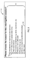
- FIG. 3 illustrates an example of a prompt 300 that may be shown to a user of the CRM system.
- the prompt 300 of FIG. 3 is adapted to be shown on a video display device of a programmer in use in a hospital or clinic.
- the user is presented with a list of choices 304 of reasons for the transmission session.
- the list of choices 304 in this embodiment includes hospitalization for heart failure decompensation, that a VT/VF shock has been received by the patient, having leads checked, having non-cardiac complications such as a stroke or hypertension, and resolving a red or yellow alert.
- the user is offered the choice of "other reason" and provided with a field 308 for describing the other reason.
- a transmission session can occur in response to a patient complaint or request, such as a complaint about shortness of breath, fatigue, non-cardiac stimulations, or beeping. These reasons can be described in the field 308.
- additional reasons may be provided within the prompt 300.
- Each of the reasons in the list of reasons 304 has a checkbox 310 provided so that the user can select one of the reasons.
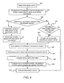
- FIG. 4 illustrates another embodiment of the steps of a CRM system.
- a transmission session is initiated at step 400. If the external interface device is connected to a patient management system, the external interface device collects information about any alerts issued by the patient management session during the period since the last transmission session at step 404.
- the system checks to see if a new event or alert has been issued by either the patient management system or the CRM device since the last transmission session at step 408.
- An example of an event that would be recorded by the CRM device includes the administration of a VT/VF shock. If the answer to the query at step 408 is yes, then the programmer chooses a likely or anticipated reason for the transmission session at step 410 that aligns with the recent event or alert information.
- the programmer chooses an anticipated reason for the transmission session as administration of a VT/VF shock. If there was a red or yellow alert since the last transmission session, the system chooses an anticipated reason of resolving the red or yellow alert.
- the various sensor information collected by the CRM device may have been analyzed either by the CRM device itself or by the patient management system to detect a heart failure decompensation event.
- the user is provided with the anticipated reason along with a list of other possible reasons at step 414.
- the anticipated reason can be indicated by the presence of a check in a checkbox 310. The user can quickly accept the anticipated reason or can uncheck the anticipated reason if it is incorrect.
- a filter can be applied to the process of prompting the user for a reason for the transmission session. Redundant prompts may arise when multiple transmission sessions follow a particular event. If the answer to the query at step 408 was no, then the system may optionally check to see if there was a transmission session within a previous time period, such as within a certain number of days, at step 416. If no transmission session and accompanying prompt occurred within the certain number of days, then the user is prompted to select the reason for the transmission session at step 420.
- the number of days used in the filter may be 1, 2, 3, 4, or other numbers.
- the number of days used in the filter varies depending on the reason entered for the previous transmission session. For example, in box 416, X may be one day if the reason for the previous transmission session was a lead check or for VT/VF shock received. In another example, X may be seven days if the reason for the previous transmission session was a hospitalization.
- the input of the selection or confirmation of the reason for the session is received at step 422.
- the external interface device sends the reason and the timestamp to the CRM device for storage of that information at step 424.
- the implanted device stores the event information at step 426. If the external interface device is connected or later connected to the patient management computer system, then it uploads the reason and timestamp information to the patient management computer system at step 428.
- the transmission session continues at step 430.
- Steps 408-414 of pre-selecting an anticipated reason for the transmission session are optional steps.
- step 416 of applying a filter is an optional step.
- FIG. 4 can apply to transmission sessions initiated either by a programmer or a patient-operated communicator.
- FIG. 5 shows steps that are especially suited for the situation where a patient initiates a transmission session when they are remote from a hospital or clinic.
- a patient initiates a transmission session with an implanted device at step 502 using an external interface device, such as a communicator.
- a display device of the communicator prompts the user to select a reason for the session at step 504, which may include a list of appropriate reasons from which the patient can select.
- FIG. 6 is an example of a prompt 602 that may be presented to the patient. The patient may be asked, "Why did you start this session?"
- the patient may also be presented with a list of reasons 604 from which to choose, where each reason can be selected using one of the checkboxes 606. Examples of reasons that would be relevant to a patient who is conducting a remote monitoring session include that the patient was asked to initiate a session after receiving a shock, that the patient was asked to initiate a session because of an alert, and other reasons that the patient can describe in a field 608.
- the patient inputs a selected reason at step 506, such as by checking a check-box. It is also possible that an anticipated reason has been selected by the system in response to recent events, as described above with respect to FIG. 4 .
- the transmission session continues and concludes at step 508, resulting in the selected reason, timestamp, and interrogated data being sent to the patient management computer system at step 510.
- personnel at the clinic review the data downloaded during the remote transmission session at step 512.
- the system may prompt the user to confirm the patient-selected reason for the transmission session, or enter a different reason, at step 514.
- FIG. 7 is a schematic of one embodiment that is particularly suited to use in a patient's home.
- An implantable device 714 implanted within a patient 712, is in communication with an external interface device 716 that can have a visual output in the form of a display screen 718 and an audio output in the form of a speaker 720.
- the implantable medical device 714 can include one or more leads 722 disposed in or near the patient's heart 726.
- Buttons 721 provide a means for patient input.
- the display screen 718 may be a touch screen which provides additional avenues for patient input. Communication with the implantable device 714 can be through radio frequency, inductive transmission, acoustically, or any other means available.
- the external interface device 716 can be a component of a patient monitoring system for use by a patient in his home or residence.
- An exemplary in-home monitoring system is the LATITUDE ® patient management system, available from Boston Scientific Corporation, Natick, MA. Aspects of exemplary in-home monitoring systems are described in U.S. Pat. No. 6,978,182 .
- the external interface device 716 can be in communication with an additional processing device such as a workstation or server located remotely from the external interface device 716 to enable access to the information by doctors or technicians.
- the external interface device 716 can be in communication with a patient management computer system 732 through the Internet 730 or another type of data connection.
- the external interface device can be a mobile device (not shown), such as a hand-held device or a device worn on a belt.
- the invention includes a device including a graphical display and a machine-readable medium comprising instructions.
- the instructions can perform various operations when implemented by one or more processors.
- the operations can include those in accordance with methods as described herein.
- the machine-readable medium can include random access memory (RAM), read-only memory (ROM), magnetic data storage media, optical data storage media, flash memory, and the like.
- External interface devices to display information can include components common to many computing devices.
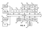
- FIG. 8 a diagram of various components is shown in accordance with some embodiments of the invention. However, it is not required that an external interface device have all of the components illustrated in FIG. 8 .
- the external interface device includes a central processing unit (CPU) 805 or processor, which may include a conventional microprocessor, random access memory (RAM) 810 for temporary storage of information, and read only memory (ROM) 815 for permanent storage of information.
- CPU central processing unit
- RAM random access memory
- ROM read only memory
- a memory controller 820 is provided for controlling system RAM 810.
- a bus controller 825 is provided for controlling data bus 830, and an interrupt controller 835 is used for receiving and processing various interrupt signals from the other system components.
- Mass storage can be provided by diskette drive 841, which is connected to bus 830 by controller 840, CD-ROM drive 846, which is connected to bus 830 by controller 845, and hard disk drive 851, which is connected to bus 830 by controller 850.
- User input to the programmer system may be provided by a number of devices.
- a keyboard and mouse can be connected to bus 830 by keyboard and mouse controller 855.
- DMA controller 860 is provided for performing direct memory access to system RAM 810.
- a visual display is generated by a video controller 865 or video output, which controls video display 870.
- the external system can also include a telemetry interface 890 or telemetry circuit, which allows the external system to interface and exchange data with an implantable medical device. It will be appreciated that some embodiments may lack various elements illustrated in FIG. 8 .
- the implantable medical system 900 can include an implantable medical device 972 coupled to one or more stimulation leads 930 and 928.
- the implantable device 972 can also include other sensors, such as activity sensor 962.
- the implantable device can include a microprocessor 948 (or processor) that communicates with a memory 946 via a bidirectional data bus.
- the memory 946 typically comprises ROM or RAM for program storage and RAM for data storage.
- the implantable device can be configured to execute various operations such as processing of signals and execution of methods as described herein.
- a telemetry interface 964 is also provided for communicating with an external unit, such as a programmer device or a patient management system.
- the implantable device can include ventricular sensing and pacing channels comprising sensing amplifier 952, output circuit 954, and a ventricular channel interface 950 which communicates bidirectionally with a port of microprocessor 948.
- the ventricular sensing and pacing channel can be in communication with stimulation lead 930 and electrode 934.
- the implantable device can include atrial sensing and pacing channels comprising sensing amplifier 958, output circuit 960, and an atrial channel interface 956 which communicates bidirectionally with a port of microprocessor 948.
- the atrial sensing and pacing channel can be in communication with stimulation lead 928 and electrode 932. For each channel, the same lead and electrode can be used for both sensing and pacing.
- the channel interfaces 950 and 956 can include analog-to-digital converters for digitizing sensing signal inputs from the sensing amplifiers and registers, which can be written to by the microprocessor in order to output pacing pulses, change the pacing pulse amplitude, and adjust the gain and threshold values for the sensing amplifiers.
- the phrase “configured” describes a system, apparatus, or other structure that is constructed or configured to perform a particular task or adopt a particular configuration.
- the phrase “configured” can be used interchangeably with other similar phrases such as “arranged”, “arranged and configured”, “constructed and arranged”, “constructed”, “manufactured and arranged”, and the like.
- modules, circuitry, and methods shown and described herein with regard to various embodiments of the invention can be implemented using software, hardware, and combinations of software and hardware.
- the illustrated and/or described modules and circuitry are intended to encompass software implementations, hardware implementations, and software and hardware implementations.
Landscapes
- Health & Medical Sciences (AREA)
- Engineering & Computer Science (AREA)
- Biomedical Technology (AREA)
- General Health & Medical Sciences (AREA)
- Public Health (AREA)
- Nuclear Medicine, Radiotherapy & Molecular Imaging (AREA)
- Life Sciences & Earth Sciences (AREA)
- Animal Behavior & Ethology (AREA)
- Radiology & Medical Imaging (AREA)
- Human Computer Interaction (AREA)
- Veterinary Medicine (AREA)
- Business, Economics & Management (AREA)
- General Business, Economics & Management (AREA)
- Epidemiology (AREA)
- Medical Informatics (AREA)
- Primary Health Care (AREA)
- Electrotherapy Devices (AREA)
- Measuring And Recording Apparatus For Diagnosis (AREA)
Claims (15)
- Procédé de collecte d'informations sur des événements survenant à un patient, en provenance d'un système de gestion du rythme cardiaque (système CRM) (100) comprenant un dispositif de gestion du rythme cardiaque (dispositif CRM) et un dispositif externe d'interface, le procédé comportant les étapes qui consistent à :lancer (200) une session de transmission dans laquelle le dispositif d'interface communique avec le dispositif CRM,inviter (204) un utilisateur du système CRM à sélectionner une raison à l'origine de la session de transmission,introduire (206) la raison sélectionnée pour la session de transmission dans le dispositif d'interface etconserver (208) la raison sélectionnée de la session de transmission et une information de balise temporelle de la session de transmission.
- Procédé selon la revendication 1, comportant en outre l'étape qui consiste à transmettre la raison sélectionnée et l'information de balise temporelle à un système d'ordinateur de gestion de patients raccordé au système CRM de manière à pouvoir communiquer avec lui.
- Procédé selon la revendication 1, dans lequel l'étape consistant à inviter l'utilisateur comprend l'action qui consiste à inviter l'utilisateur à sélectionner la raison de la session de transmission dans une liste (304) de raisons.
- Procédé selon la revendication 3, dans lequel l'étape consistant à inviter l'utilisateur comprend en outre la présélection (414) d'une raison anticipée de la session de transmission dans la liste (304) de raisons, la présélection de la raison anticipée étant basée sur des informations récentes d'activité en provenance du système CRM.
- Procédé selon la revendication 4, dans lequel l'information récente concernant l'activité en provenance du système CRM comprend une information concernant la survenance de l'un des événements suivants : application d'un choc par le dispositif CRM, émission d'une alerte par le système CRM et détection d'une décompensation d'une défaillance cardiaque par le dispositif CRM.
- Procédé selon la revendication 1, dans lequel l'utilisateur est un patient (112), le dispositif CRM (114) étant implanté dans le patient et le patient lançant l'étape de lancement (502) d'une session de transmission, le patient introduisant (504) une raison de la session de transmission dans le dispositif d'interface.
- Procédé selon la revendication 6, comprenant en outre les étapes qui consistent à :lancer (512) une session de révision des données envoyées pendant la session de transmission età inviter (514) l'utilisateur d'une session de révision à confirmer les raisons sélectionnées de la session de transmission.
- Procédé selon la revendication 1, comprenant en outre l'étape qui consiste à appliquer un filtre après le lancement d'une session de transmission et avant d'inviter un utilisateur du système CRM, le filtre déterminant si l'utilisateur a été invité à introduire une raison d'une session de transmission pendant une trame temporelle antérieure, la trame temporelle antérieure étant sélectionnée sur la base de la raison sélectionnée lors de la session de transmission la plus récente.
- Système de gestion du rythme cardiaque (CRM) (100), destiné à recueillir des informations sur des événements d'un patient, le système comprenant :un dispositif CRM implantable (114, 714),un dispositif externe d'interface (116, 716) situé à distance du dispositif CRM et comprenant :i. un module de communication (890) adapté pour être raccordé au dispositif CRM de manière à pouvoir communiquer avec lui et pour demander et recevoir des informations du dispositif CRM pendant des sessions de transmission,ii. un dispositif d'affichage (118, 718, 870) adapté pour inviter un utilisateur du système CRM à sélectionner une raison d'une session particulière de transmission,iii. un dispositif (120, 128, 718, 721) d'introduction par l'utilisateur adapté pour recevoir des introductions indiquant une raison sélectionnée,le module de communication étant configuré pour transmettre la raison sélectionnée et une information de balise temporelle de la session de transmission au dispositif CRM etle système CRM étant adapté pour conserver la raison sélectionnée et l'information de balise temporelle de la session de transmission.
- Procédé selon la revendication 1 ou système selon la revendication 9, dans lesquels le dispositif CRM implantable (900) comprend en outre une unité de mémoire (946), le système CRM étant adapté pour conserver la raison sélectionnée et l'information de balise temporelle dans l'unité de mémoire du dispositif CRM.
- Procédé selon la revendication 1 ou système selon la revendication 9, dans lesquels le dispositif externe d'interface (116, 716) comprend en outre une unité de mémoire, le système CRM étant adapté pour conserver la raison sélectionnée et l'information de balise temporelle dans l'unité de mémoire du dispositif externe d'interface.
- Système selon la revendication 9, dans lequel le système CRM comprend en outre un système informatique (132, 732) de gestion de patients raccordé au dispositif externe d'interface (116, 716) de manière à pouvoir communiquer avec lui, le système CRM étant adapté pour transmettre la raison sélectionnée et l'information de balise temporelle au système informatique.
- Système selon la revendication 9, dans lequel le dispositif externe d'interface (116, 716) est adapté pour inviter l'utilisateur à sélectionner la raison de la session de transmission dans une liste (304, 604) de raisons.
- Procédé selon la revendication 3 ou système selon la revendication 13, dans lequel la liste de raisons comprend au moins deux des raisons suivantes : hospitalisation, choc reçu, vérification des conducteurs, reprogrammation du dispositif, suivi de routine et résolution d'une alerte.
- Système selon la revendication 9, dans lequel le module de communication du dispositif externe d'interface (116, 716) est adapté pour recevoir des informations sur les activités récentes qui concernent des activités récentes du dispositif CRM et étant adapté pour présélectionner une raison anticipée de la session de transmission dans la liste de raisons, la présélection de la raison anticipée étant basée sur des informations récentes d'activité en provenance du dispositif CRM.
Applications Claiming Priority (2)
| Application Number | Priority Date | Filing Date | Title |
|---|---|---|---|
| US8124808P | 2008-07-16 | 2008-07-16 | |
| PCT/US2009/050861 WO2010009322A1 (fr) | 2008-07-16 | 2009-07-16 | Systèmes et procédés pour collecter des informations d'événement de patient |
Publications (2)
| Publication Number | Publication Date |
|---|---|
| EP2340084A1 EP2340084A1 (fr) | 2011-07-06 |
| EP2340084B1 true EP2340084B1 (fr) | 2015-03-18 |
Family
ID=41055222
Family Applications (1)
| Application Number | Title | Priority Date | Filing Date |
|---|---|---|---|
| EP09790539.2A Not-in-force EP2340084B1 (fr) | 2008-07-16 | 2009-07-16 | Systèmes et procédés pour collecter des informations d'événement de patient |
Country Status (6)
| Country | Link |
|---|---|
| US (2) | US8260423B2 (fr) |
| EP (1) | EP2340084B1 (fr) |
| JP (1) | JP5236808B2 (fr) |
| CN (1) | CN102099080B (fr) |
| AU (1) | AU2009270836C1 (fr) |
| WO (1) | WO2010009322A1 (fr) |
Families Citing this family (6)
| Publication number | Priority date | Publication date | Assignee | Title |
|---|---|---|---|---|
| AU2009270836C1 (en) | 2008-07-16 | 2015-02-19 | Cardiac Pacemakers, Inc. | Systems and methods for collecting patient event information |
| AU2010215784B2 (en) * | 2009-02-20 | 2015-04-30 | Sage Products, Llc | Systems and methods of powered muscle stimulation using an energy guidance field |
| US9020596B2 (en) | 2011-07-15 | 2015-04-28 | Cardiac Pacemakers, Inc. | Management of fusion beat detection during capture threshold determination |
| US10155118B2 (en) | 2013-08-01 | 2018-12-18 | Zoll Medical Corporation | Systems and methods for utilizing identification devices in a wearable medical therapy device |
| US20210065893A1 (en) * | 2018-01-24 | 2021-03-04 | Biotronik Se & Co. Kg | Method to Encourage Patient Feedback on Interaction with Device |
| CA3137307A1 (fr) | 2019-05-06 | 2020-11-12 | CARDIONOMIC, Inc. | Systemes et procedes de debruitage de signaux physiologiques pendant une neuromodulation electrique |
Family Cites Families (17)
| Publication number | Priority date | Publication date | Assignee | Title |
|---|---|---|---|---|
| US5722999A (en) * | 1995-08-02 | 1998-03-03 | Pacesetter, Inc. | System and method for storing and displaying historical medical data measured by an implantable medical device |
| US6263245B1 (en) * | 1999-08-12 | 2001-07-17 | Pacesetter, Inc. | System and method for portable implantable device interogation |
| US6535763B1 (en) * | 1999-08-22 | 2003-03-18 | Cardia Pacemakers, Inc. | Event marker alignment by inclusion of event marker transmission latency in the real-time data stream |
| US6665558B2 (en) * | 2000-12-15 | 2003-12-16 | Cardiac Pacemakers, Inc. | System and method for correlation of patient health information and implant device data |
| US7383088B2 (en) * | 2001-11-07 | 2008-06-03 | Cardiac Pacemakers, Inc. | Centralized management system for programmable medical devices |
| US7983759B2 (en) * | 2002-12-18 | 2011-07-19 | Cardiac Pacemakers, Inc. | Advanced patient management for reporting multiple health-related parameters |
| US8391989B2 (en) * | 2002-12-18 | 2013-03-05 | Cardiac Pacemakers, Inc. | Advanced patient management for defining, identifying and using predetermined health-related events |
| US7801596B2 (en) * | 2002-09-20 | 2010-09-21 | Angel Medical Systems, Inc. | Physician's programmer for implantable devices having cardiac diagnostic and patient alerting capabilities |
| US6978182B2 (en) * | 2002-12-27 | 2005-12-20 | Cardiac Pacemakers, Inc. | Advanced patient management system including interrogator/transceiver unit |
| US7536224B2 (en) | 2003-04-30 | 2009-05-19 | Medtronic, Inc. | Method for elimination of ventricular pro-arrhythmic effect caused by atrial therapy |
| US7697993B2 (en) * | 2004-05-13 | 2010-04-13 | Cardiac Pacemakers, Inc. | Method and apparatus for question-based programming of cardiac rhythm management devices |
| US20060064136A1 (en) * | 2004-09-23 | 2006-03-23 | Medtronic, Inc. | Method and apparatus for facilitating patient alert in implantable medical devices |
| US7894905B2 (en) * | 2006-03-13 | 2011-02-22 | Neuropace, Inc. | Implantable system enabling responsive therapy for pain |
| WO2008008009A1 (fr) * | 2006-07-13 | 2008-01-17 | St. Jude Medical Ab | Gestion d'informations médicales dans un système de concentrateur d'informations concernant le patient |
| US10311533B2 (en) * | 2006-12-27 | 2019-06-04 | Cardiac Pacemakers, Inc. | Method and system to enable physician labels on a remote server and use labels to verify and improve algorithm results |
| US20090063193A1 (en) * | 2007-08-31 | 2009-03-05 | Mike Barton | Dashboard diagnostics for wireless patient communicator |
| AU2009270836C1 (en) | 2008-07-16 | 2015-02-19 | Cardiac Pacemakers, Inc. | Systems and methods for collecting patient event information |
-
2009
- 2009-07-16 AU AU2009270836A patent/AU2009270836C1/en not_active Ceased
- 2009-07-16 CN CN200980128274.6A patent/CN102099080B/zh not_active Expired - Fee Related
- 2009-07-16 EP EP09790539.2A patent/EP2340084B1/fr not_active Not-in-force
- 2009-07-16 WO PCT/US2009/050861 patent/WO2010009322A1/fr not_active Ceased
- 2009-07-16 JP JP2011518915A patent/JP5236808B2/ja active Active
- 2009-07-16 US US12/504,450 patent/US8260423B2/en active Active
-
2012
- 2012-08-07 US US13/568,958 patent/US8600506B2/en not_active Expired - Fee Related
Also Published As
| Publication number | Publication date |
|---|---|
| EP2340084A1 (fr) | 2011-07-06 |
| CN102099080A (zh) | 2011-06-15 |
| WO2010009322A1 (fr) | 2010-01-21 |
| JP5236808B2 (ja) | 2013-07-17 |
| US8260423B2 (en) | 2012-09-04 |
| AU2009270836C1 (en) | 2015-02-19 |
| AU2009270836A1 (en) | 2010-01-21 |
| US20100016920A1 (en) | 2010-01-21 |
| JP2011528274A (ja) | 2011-11-17 |
| CN102099080B (zh) | 2016-06-15 |
| US8600506B2 (en) | 2013-12-03 |
| AU2009270836B2 (en) | 2014-07-10 |
| US20120303086A1 (en) | 2012-11-29 |
Similar Documents
| Publication | Publication Date | Title |
|---|---|---|
| EP2216071B1 (fr) | Système pour une programmation de dispositif médical fondée sur des indications | |
| US9538919B2 (en) | System and method for improved ischemia and acute myocardial infarction detection | |
| US8600506B2 (en) | Systems and methods for collecting patient event information | |
| WO2010005804A1 (fr) | Système et procédé de détection de l’infarctus aigu du myocarde | |
| EP4049713B1 (fr) | Système et procédé pour la programmation à distance de paramètres d'irm d'un dispositif médical implantable | |
| EP3179908B1 (fr) | Système et procédé d'analyse de sonde implantée | |
| US9731137B2 (en) | Systems and methods to identify the inability to exercise to desired capacity | |
| US9259586B2 (en) | Systems and methods for highly safe adjustment of device parameters | |
| US9357935B2 (en) | Systems and methods to identify cardiac dysynchrony |
Legal Events
| Date | Code | Title | Description |
|---|---|---|---|
| PUAI | Public reference made under article 153(3) epc to a published international application that has entered the european phase |
Free format text: ORIGINAL CODE: 0009012 |
|
| 17P | Request for examination filed |
Effective date: 20110215 |
|
| AK | Designated contracting states |
Kind code of ref document: A1 Designated state(s): AT BE BG CH CY CZ DE DK EE ES FI FR GB GR HR HU IE IS IT LI LT LU LV MC MK MT NL NO PL PT RO SE SI SK SM TR |
|
| AX | Request for extension of the european patent |
Extension state: AL BA RS |
|
| DAX | Request for extension of the european patent (deleted) | ||
| GRAP | Despatch of communication of intention to grant a patent |
Free format text: ORIGINAL CODE: EPIDOSNIGR1 |
|
| INTG | Intention to grant announced |
Effective date: 20141202 |
|
| GRAS | Grant fee paid |
Free format text: ORIGINAL CODE: EPIDOSNIGR3 |
|
| GRAA | (expected) grant |
Free format text: ORIGINAL CODE: 0009210 |
|
| AK | Designated contracting states |
Kind code of ref document: B1 Designated state(s): AT BE BG CH CY CZ DE DK EE ES FI FR GB GR HR HU IE IS IT LI LT LU LV MC MK MT NL NO PL PT RO SE SI SK SM TR |
|
| REG | Reference to a national code |
Ref country code: GB Ref legal event code: FG4D |
|
| REG | Reference to a national code |
Ref country code: CH Ref legal event code: EP |
|
| REG | Reference to a national code |
Ref country code: IE Ref legal event code: FG4D |
|
| REG | Reference to a national code |
Ref country code: AT Ref legal event code: REF Ref document number: 716150 Country of ref document: AT Kind code of ref document: T Effective date: 20150415 |
|
| REG | Reference to a national code |
Ref country code: DE Ref legal event code: R096 Ref document number: 602009030081 Country of ref document: DE Effective date: 20150430 |
|
| REG | Reference to a national code |
Ref country code: NL Ref legal event code: T3 |
|
| REG | Reference to a national code |
Ref country code: FR Ref legal event code: PLFP Year of fee payment: 7 |
|
| PG25 | Lapsed in a contracting state [announced via postgrant information from national office to epo] |
Ref country code: NO Free format text: LAPSE BECAUSE OF FAILURE TO SUBMIT A TRANSLATION OF THE DESCRIPTION OR TO PAY THE FEE WITHIN THE PRESCRIBED TIME-LIMIT Effective date: 20150618 Ref country code: FI Free format text: LAPSE BECAUSE OF FAILURE TO SUBMIT A TRANSLATION OF THE DESCRIPTION OR TO PAY THE FEE WITHIN THE PRESCRIBED TIME-LIMIT Effective date: 20150318 Ref country code: HR Free format text: LAPSE BECAUSE OF FAILURE TO SUBMIT A TRANSLATION OF THE DESCRIPTION OR TO PAY THE FEE WITHIN THE PRESCRIBED TIME-LIMIT Effective date: 20150318 Ref country code: LT Free format text: LAPSE BECAUSE OF FAILURE TO SUBMIT A TRANSLATION OF THE DESCRIPTION OR TO PAY THE FEE WITHIN THE PRESCRIBED TIME-LIMIT Effective date: 20150318 Ref country code: SE Free format text: LAPSE BECAUSE OF FAILURE TO SUBMIT A TRANSLATION OF THE DESCRIPTION OR TO PAY THE FEE WITHIN THE PRESCRIBED TIME-LIMIT Effective date: 20150318 |
|
| REG | Reference to a national code |
Ref country code: AT Ref legal event code: MK05 Ref document number: 716150 Country of ref document: AT Kind code of ref document: T Effective date: 20150318 |
|
| REG | Reference to a national code |
Ref country code: LT Ref legal event code: MG4D |
|
| PG25 | Lapsed in a contracting state [announced via postgrant information from national office to epo] |
Ref country code: GR Free format text: LAPSE BECAUSE OF FAILURE TO SUBMIT A TRANSLATION OF THE DESCRIPTION OR TO PAY THE FEE WITHIN THE PRESCRIBED TIME-LIMIT Effective date: 20150619 Ref country code: LV Free format text: LAPSE BECAUSE OF FAILURE TO SUBMIT A TRANSLATION OF THE DESCRIPTION OR TO PAY THE FEE WITHIN THE PRESCRIBED TIME-LIMIT Effective date: 20150318 |
|
| PG25 | Lapsed in a contracting state [announced via postgrant information from national office to epo] |
Ref country code: PT Free format text: LAPSE BECAUSE OF FAILURE TO SUBMIT A TRANSLATION OF THE DESCRIPTION OR TO PAY THE FEE WITHIN THE PRESCRIBED TIME-LIMIT Effective date: 20150720 Ref country code: RO Free format text: LAPSE BECAUSE OF FAILURE TO SUBMIT A TRANSLATION OF THE DESCRIPTION OR TO PAY THE FEE WITHIN THE PRESCRIBED TIME-LIMIT Effective date: 20150318 Ref country code: SK Free format text: LAPSE BECAUSE OF FAILURE TO SUBMIT A TRANSLATION OF THE DESCRIPTION OR TO PAY THE FEE WITHIN THE PRESCRIBED TIME-LIMIT Effective date: 20150318 Ref country code: ES Free format text: LAPSE BECAUSE OF FAILURE TO SUBMIT A TRANSLATION OF THE DESCRIPTION OR TO PAY THE FEE WITHIN THE PRESCRIBED TIME-LIMIT Effective date: 20150318 Ref country code: CZ Free format text: LAPSE BECAUSE OF FAILURE TO SUBMIT A TRANSLATION OF THE DESCRIPTION OR TO PAY THE FEE WITHIN THE PRESCRIBED TIME-LIMIT Effective date: 20150318 Ref country code: EE Free format text: LAPSE BECAUSE OF FAILURE TO SUBMIT A TRANSLATION OF THE DESCRIPTION OR TO PAY THE FEE WITHIN THE PRESCRIBED TIME-LIMIT Effective date: 20150318 |
|
| PG25 | Lapsed in a contracting state [announced via postgrant information from national office to epo] |
Ref country code: IS Free format text: LAPSE BECAUSE OF FAILURE TO SUBMIT A TRANSLATION OF THE DESCRIPTION OR TO PAY THE FEE WITHIN THE PRESCRIBED TIME-LIMIT Effective date: 20150718 Ref country code: PL Free format text: LAPSE BECAUSE OF FAILURE TO SUBMIT A TRANSLATION OF THE DESCRIPTION OR TO PAY THE FEE WITHIN THE PRESCRIBED TIME-LIMIT Effective date: 20150318 Ref country code: AT Free format text: LAPSE BECAUSE OF FAILURE TO SUBMIT A TRANSLATION OF THE DESCRIPTION OR TO PAY THE FEE WITHIN THE PRESCRIBED TIME-LIMIT Effective date: 20150318 |
|
| REG | Reference to a national code |
Ref country code: DE Ref legal event code: R097 Ref document number: 602009030081 Country of ref document: DE |
|
| PG25 | Lapsed in a contracting state [announced via postgrant information from national office to epo] |
Ref country code: IT Free format text: LAPSE BECAUSE OF FAILURE TO SUBMIT A TRANSLATION OF THE DESCRIPTION OR TO PAY THE FEE WITHIN THE PRESCRIBED TIME-LIMIT Effective date: 20150318 |
|
| REG | Reference to a national code |
Ref country code: DE Ref legal event code: R082 Ref document number: 602009030081 Country of ref document: DE Representative=s name: PETERREINS SCHLEY PATENT- UND RECHTSANWAELTE P, DE Ref country code: DE Ref legal event code: R082 Ref document number: 602009030081 Country of ref document: DE Representative=s name: PETERREINS SCHLEY PATENT- UND RECHTSANWAELTE, DE |
|
| PLBE | No opposition filed within time limit |
Free format text: ORIGINAL CODE: 0009261 |
|
| STAA | Information on the status of an ep patent application or granted ep patent |
Free format text: STATUS: NO OPPOSITION FILED WITHIN TIME LIMIT |
|
| PG25 | Lapsed in a contracting state [announced via postgrant information from national office to epo] |
Ref country code: DK Free format text: LAPSE BECAUSE OF FAILURE TO SUBMIT A TRANSLATION OF THE DESCRIPTION OR TO PAY THE FEE WITHIN THE PRESCRIBED TIME-LIMIT Effective date: 20150318 |
|
| 26N | No opposition filed |
Effective date: 20151221 |
|
| PG25 | Lapsed in a contracting state [announced via postgrant information from national office to epo] |
Ref country code: SI Free format text: LAPSE BECAUSE OF FAILURE TO SUBMIT A TRANSLATION OF THE DESCRIPTION OR TO PAY THE FEE WITHIN THE PRESCRIBED TIME-LIMIT Effective date: 20150318 Ref country code: MC Free format text: LAPSE BECAUSE OF FAILURE TO SUBMIT A TRANSLATION OF THE DESCRIPTION OR TO PAY THE FEE WITHIN THE PRESCRIBED TIME-LIMIT Effective date: 20150318 |
|
| REG | Reference to a national code |
Ref country code: CH Ref legal event code: PL |
|
| GBPC | Gb: european patent ceased through non-payment of renewal fee |
Effective date: 20150716 |
|
| PG25 | Lapsed in a contracting state [announced via postgrant information from national office to epo] |
Ref country code: LU Free format text: LAPSE BECAUSE OF FAILURE TO SUBMIT A TRANSLATION OF THE DESCRIPTION OR TO PAY THE FEE WITHIN THE PRESCRIBED TIME-LIMIT Effective date: 20150716 |
|
| REG | Reference to a national code |
Ref country code: IE Ref legal event code: MM4A |
|
| PG25 | Lapsed in a contracting state [announced via postgrant information from national office to epo] |
Ref country code: GB Free format text: LAPSE BECAUSE OF NON-PAYMENT OF DUE FEES Effective date: 20150716 Ref country code: CH Free format text: LAPSE BECAUSE OF NON-PAYMENT OF DUE FEES Effective date: 20150731 Ref country code: LI Free format text: LAPSE BECAUSE OF NON-PAYMENT OF DUE FEES Effective date: 20150731 |
|
| REG | Reference to a national code |
Ref country code: FR Ref legal event code: PLFP Year of fee payment: 8 |
|
| PG25 | Lapsed in a contracting state [announced via postgrant information from national office to epo] |
Ref country code: IE Free format text: LAPSE BECAUSE OF NON-PAYMENT OF DUE FEES Effective date: 20150716 |
|
| PG25 | Lapsed in a contracting state [announced via postgrant information from national office to epo] |
Ref country code: BE Free format text: LAPSE BECAUSE OF FAILURE TO SUBMIT A TRANSLATION OF THE DESCRIPTION OR TO PAY THE FEE WITHIN THE PRESCRIBED TIME-LIMIT Effective date: 20150318 |
|
| PG25 | Lapsed in a contracting state [announced via postgrant information from national office to epo] |
Ref country code: MT Free format text: LAPSE BECAUSE OF FAILURE TO SUBMIT A TRANSLATION OF THE DESCRIPTION OR TO PAY THE FEE WITHIN THE PRESCRIBED TIME-LIMIT Effective date: 20150318 |
|
| PG25 | Lapsed in a contracting state [announced via postgrant information from national office to epo] |
Ref country code: SM Free format text: LAPSE BECAUSE OF FAILURE TO SUBMIT A TRANSLATION OF THE DESCRIPTION OR TO PAY THE FEE WITHIN THE PRESCRIBED TIME-LIMIT Effective date: 20150318 Ref country code: BG Free format text: LAPSE BECAUSE OF FAILURE TO SUBMIT A TRANSLATION OF THE DESCRIPTION OR TO PAY THE FEE WITHIN THE PRESCRIBED TIME-LIMIT Effective date: 20150318 Ref country code: HU Free format text: LAPSE BECAUSE OF FAILURE TO SUBMIT A TRANSLATION OF THE DESCRIPTION OR TO PAY THE FEE WITHIN THE PRESCRIBED TIME-LIMIT; INVALID AB INITIO Effective date: 20090716 |
|
| REG | Reference to a national code |
Ref country code: FR Ref legal event code: PLFP Year of fee payment: 9 |
|
| PG25 | Lapsed in a contracting state [announced via postgrant information from national office to epo] |
Ref country code: CY Free format text: LAPSE BECAUSE OF FAILURE TO SUBMIT A TRANSLATION OF THE DESCRIPTION OR TO PAY THE FEE WITHIN THE PRESCRIBED TIME-LIMIT Effective date: 20150318 |
|
| PG25 | Lapsed in a contracting state [announced via postgrant information from national office to epo] |
Ref country code: TR Free format text: LAPSE BECAUSE OF FAILURE TO SUBMIT A TRANSLATION OF THE DESCRIPTION OR TO PAY THE FEE WITHIN THE PRESCRIBED TIME-LIMIT Effective date: 20150318 |
|
| REG | Reference to a national code |
Ref country code: FR Ref legal event code: PLFP Year of fee payment: 10 |
|
| PG25 | Lapsed in a contracting state [announced via postgrant information from national office to epo] |
Ref country code: MK Free format text: LAPSE BECAUSE OF FAILURE TO SUBMIT A TRANSLATION OF THE DESCRIPTION OR TO PAY THE FEE WITHIN THE PRESCRIBED TIME-LIMIT Effective date: 20150318 |
|
| PGFP | Annual fee paid to national office [announced via postgrant information from national office to epo] |
Ref country code: FR Payment date: 20190619 Year of fee payment: 11 Ref country code: NL Payment date: 20190712 Year of fee payment: 11 |
|
| PGFP | Annual fee paid to national office [announced via postgrant information from national office to epo] |
Ref country code: DE Payment date: 20190702 Year of fee payment: 11 |
|
| REG | Reference to a national code |
Ref country code: DE Ref legal event code: R119 Ref document number: 602009030081 Country of ref document: DE |
|
| REG | Reference to a national code |
Ref country code: NL Ref legal event code: MM Effective date: 20200801 |
|
| PG25 | Lapsed in a contracting state [announced via postgrant information from national office to epo] |
Ref country code: FR Free format text: LAPSE BECAUSE OF NON-PAYMENT OF DUE FEES Effective date: 20200731 Ref country code: NL Free format text: LAPSE BECAUSE OF NON-PAYMENT OF DUE FEES Effective date: 20200801 |
|
| PG25 | Lapsed in a contracting state [announced via postgrant information from national office to epo] |
Ref country code: DE Free format text: LAPSE BECAUSE OF NON-PAYMENT OF DUE FEES Effective date: 20210202 |