EP2340417B1 - Dispositif de mesure de position absolue - Google Patents
Dispositif de mesure de position absolue Download PDFInfo
- Publication number
- EP2340417B1 EP2340417B1 EP09778793.1A EP09778793A EP2340417B1 EP 2340417 B1 EP2340417 B1 EP 2340417B1 EP 09778793 A EP09778793 A EP 09778793A EP 2340417 B1 EP2340417 B1 EP 2340417B1
- Authority
- EP
- European Patent Office
- Prior art keywords
- code
- sequence
- code sequence
- angle
- absolute angle
- Prior art date
- Legal status (The legal status is an assumption and is not a legal conclusion. Google has not performed a legal analysis and makes no representation as to the accuracy of the status listed.)
- Active
Links
Images


Classifications
-
- G—PHYSICS
- G01—MEASURING; TESTING
- G01D—MEASURING NOT SPECIALLY ADAPTED FOR A SPECIFIC VARIABLE; ARRANGEMENTS FOR MEASURING TWO OR MORE VARIABLES NOT COVERED IN A SINGLE OTHER SUBCLASS; TARIFF METERING APPARATUS; MEASURING OR TESTING NOT OTHERWISE PROVIDED FOR
- G01D5/00—Mechanical means for transferring the output of a sensing member; Means for converting the output of a sensing member to another variable where the form or nature of the sensing member does not constrain the means for converting; Transducers not specially adapted for a specific variable
- G01D5/26—Mechanical means for transferring the output of a sensing member; Means for converting the output of a sensing member to another variable where the form or nature of the sensing member does not constrain the means for converting; Transducers not specially adapted for a specific variable characterised by optical transfer means, i.e. using infrared, visible, or ultraviolet light
- G01D5/32—Mechanical means for transferring the output of a sensing member; Means for converting the output of a sensing member to another variable where the form or nature of the sensing member does not constrain the means for converting; Transducers not specially adapted for a specific variable characterised by optical transfer means, i.e. using infrared, visible, or ultraviolet light with attenuation or whole or partial obturation of beams of light
- G01D5/34—Mechanical means for transferring the output of a sensing member; Means for converting the output of a sensing member to another variable where the form or nature of the sensing member does not constrain the means for converting; Transducers not specially adapted for a specific variable characterised by optical transfer means, i.e. using infrared, visible, or ultraviolet light with attenuation or whole or partial obturation of beams of light the beams of light being detected by photocells
- G01D5/347—Mechanical means for transferring the output of a sensing member; Means for converting the output of a sensing member to another variable where the form or nature of the sensing member does not constrain the means for converting; Transducers not specially adapted for a specific variable characterised by optical transfer means, i.e. using infrared, visible, or ultraviolet light with attenuation or whole or partial obturation of beams of light the beams of light being detected by photocells using displacement encoding scales
- G01D5/3473—Circular or rotary encoders
-
- G—PHYSICS
- G01—MEASURING; TESTING
- G01D—MEASURING NOT SPECIALLY ADAPTED FOR A SPECIFIC VARIABLE; ARRANGEMENTS FOR MEASURING TWO OR MORE VARIABLES NOT COVERED IN A SINGLE OTHER SUBCLASS; TARIFF METERING APPARATUS; MEASURING OR TESTING NOT OTHERWISE PROVIDED FOR
- G01D5/00—Mechanical means for transferring the output of a sensing member; Means for converting the output of a sensing member to another variable where the form or nature of the sensing member does not constrain the means for converting; Transducers not specially adapted for a specific variable
- G01D5/12—Mechanical means for transferring the output of a sensing member; Means for converting the output of a sensing member to another variable where the form or nature of the sensing member does not constrain the means for converting; Transducers not specially adapted for a specific variable using electric or magnetic means
- G01D5/244—Mechanical means for transferring the output of a sensing member; Means for converting the output of a sensing member to another variable where the form or nature of the sensing member does not constrain the means for converting; Transducers not specially adapted for a specific variable using electric or magnetic means influencing characteristics of pulses or pulse trains; generating pulses or pulse trains
- G01D5/245—Mechanical means for transferring the output of a sensing member; Means for converting the output of a sensing member to another variable where the form or nature of the sensing member does not constrain the means for converting; Transducers not specially adapted for a specific variable using electric or magnetic means influencing characteristics of pulses or pulse trains; generating pulses or pulse trains using a variable number of pulses in a train
- G01D5/2454—Encoders incorporating incremental and absolute signals
- G01D5/2455—Encoders incorporating incremental and absolute signals with incremental and absolute tracks on the same encoder
-
- G—PHYSICS
- G01—MEASURING; TESTING
- G01D—MEASURING NOT SPECIALLY ADAPTED FOR A SPECIFIC VARIABLE; ARRANGEMENTS FOR MEASURING TWO OR MORE VARIABLES NOT COVERED IN A SINGLE OTHER SUBCLASS; TARIFF METERING APPARATUS; MEASURING OR TESTING NOT OTHERWISE PROVIDED FOR
- G01D5/00—Mechanical means for transferring the output of a sensing member; Means for converting the output of a sensing member to another variable where the form or nature of the sensing member does not constrain the means for converting; Transducers not specially adapted for a specific variable
- G01D5/12—Mechanical means for transferring the output of a sensing member; Means for converting the output of a sensing member to another variable where the form or nature of the sensing member does not constrain the means for converting; Transducers not specially adapted for a specific variable using electric or magnetic means
- G01D5/244—Mechanical means for transferring the output of a sensing member; Means for converting the output of a sensing member to another variable where the form or nature of the sensing member does not constrain the means for converting; Transducers not specially adapted for a specific variable using electric or magnetic means influencing characteristics of pulses or pulse trains; generating pulses or pulse trains
- G01D5/249—Mechanical means for transferring the output of a sensing member; Means for converting the output of a sensing member to another variable where the form or nature of the sensing member does not constrain the means for converting; Transducers not specially adapted for a specific variable using electric or magnetic means influencing characteristics of pulses or pulse trains; generating pulses or pulse trains using pulse code
- G01D5/2492—Pulse stream
- G01D5/2495—Pseudo-random code
-
- G—PHYSICS
- G01—MEASURING; TESTING
- G01D—MEASURING NOT SPECIALLY ADAPTED FOR A SPECIFIC VARIABLE; ARRANGEMENTS FOR MEASURING TWO OR MORE VARIABLES NOT COVERED IN A SINGLE OTHER SUBCLASS; TARIFF METERING APPARATUS; MEASURING OR TESTING NOT OTHERWISE PROVIDED FOR
- G01D5/00—Mechanical means for transferring the output of a sensing member; Means for converting the output of a sensing member to another variable where the form or nature of the sensing member does not constrain the means for converting; Transducers not specially adapted for a specific variable
- G01D5/12—Mechanical means for transferring the output of a sensing member; Means for converting the output of a sensing member to another variable where the form or nature of the sensing member does not constrain the means for converting; Transducers not specially adapted for a specific variable using electric or magnetic means
- G01D5/244—Mechanical means for transferring the output of a sensing member; Means for converting the output of a sensing member to another variable where the form or nature of the sensing member does not constrain the means for converting; Transducers not specially adapted for a specific variable using electric or magnetic means influencing characteristics of pulses or pulse trains; generating pulses or pulse trains
- G01D5/249—Mechanical means for transferring the output of a sensing member; Means for converting the output of a sensing member to another variable where the form or nature of the sensing member does not constrain the means for converting; Transducers not specially adapted for a specific variable using electric or magnetic means influencing characteristics of pulses or pulse trains; generating pulses or pulse trains using pulse code
- G01D5/2497—Absolute encoders
Definitions
- Absolute angle measuring devices are increasingly used to determine the position of two relatively moving bodies.
- Absolute angle measuring devices have the advantage over purely incremental measuring systems that correct position information can be output immediately in any relative position even after interruption of the supply energy.
- the absolute position is embodied by an angle coding.
- Particularly space-saving is the arrangement of the position information in a single code track with successively arranged in the measuring direction code elements.
- the code elements are arranged in pseudo-random distribution one behind the other, so that a certain number of successive code elements each forms a code word that uniquely defines the absolute position.
- a new code word is already formed and over the entire absolute extent to be detected is a sequence of different code words available.
- serial or sequential code is also often called chain code or pseudo random code (PRC).
- a decoding table is used in which each codeword is assigned a position.
- the codeword forms the address for the decoding table, so that the absolute position stored for this codeword is present at the output and is available for further processing.
- the US 6,330,522 B1 shows a measure of how an angle coding and an angle measuring device can be designed to reduce the cost of decoding.
- a first code sequence and a second code sequence are arranged in mutually parallel tracks over 360 °.
- the first code sequence is located five times over 360 ° and the second code sequence is located fourteen times over 360 °.
- the code sequences include different angular sectors.
- the bit width of the first code sequence differs from the bit width of the second code sequence.
- the decoding device has a first value store for decoding the first code sequence and a second value store for decoding the second code sequence.
- the absolute position is unique by the combination of both partial positions at each position over 360 °.
- the object of the invention is therefore to provide an angle coding, with which any number of positions over 360 ° can be uniquely coded, and with an angle encoder in a simple decoding of the generated by sampling this angular coding sequences of codewords is made possible.
- an absolute angle measuring device is specified with such an angle coding.
- the absolute angle coding has several code sequences arranged within 360 °, which in combination unambiguously absolutely encode the 360 °, of which a first code sequence consisting of a sequence of code elements, including a first angle sector and arranged several times in succession, and cyclically repeated several times, a second code sequence consisting of a sequence of code elements, including a second angle sector and arranged several times in succession, and cyclically repeated several times, wherein the first angle sector is different from the second angle sector, and at least one of the code sequences within the 360 ° is only partially formed and forms a joint with the subsequent code sequence.
- At least one of the two code sequences is only partially applied once within 360 °, and this part is connected to the next code sequence.
- this code sequence is interrupted, since this produces a collision region at which a new sequence of code elements, ie. H. new bitpattern or words, arises.
- New bitpattern means that these bitpatterns are not part of the code sequences and their cyclic continuations.
- the code sequences are arranged in a circle on a disk or over the circumference of a drum.
- a code element is in each case an area of the angle coding, from which one bit can be derived.
- Code sequence means a sequence of code elements that define different positions in the raster of a code element over the entire length of the code sequence.
- Cyclically continued code sequence means that the beginning of this same code sequence reconnects at the end of the code sequence.
- the angle coding formed according to the invention now makes it possible, in particular over 360 ° 2 k, to code different positions, preferably k> 4 and integer.
- the code elements of the first code sequence and the second code sequence preferably each include equal angular sectors. Given this, the size of an angle sector can be more easily defined by the number of code elements.
- the maximum number of different positions is obtained if the length of the first code sequence differs from the length of the second code sequence by one.
- the length of the first code sequence is the number of code elements of the first code sequence and the length of the second code sequence is the number of code elements of the second code sequence.
- first code sequence and the second code sequence are arranged in a common track, in which a part of the first code sequence and a part of the second code sequence are arranged alternately.
- Each code element of the first code sequence is followed by a single code element of the second code sequence and a code element of the second code sequence is followed by a single code element of the first code sequence.
- At least one incremental track may be arranged concentrically with the absolute angle coding.
- the pitch period of this incremental track is, for example, a fraction of the width of a code element of the code sequences A, B.
- An angle measuring device now has a detector arrangement for scanning the first and the second code sequence of the angle coding and for generating code words, as well as a decoding device for decoding the code words and for generating position values.
- the decoder device has a first value store for decoding a first sequence of codewords, which respectively arises during the sampling of one of the first code sequences and their cyclic continuation, and a second value store for decoding a second sequence of codewords, each of which is used in the sampling of one of the second code sequences and their cyclic continuation arises, and the decoding device has a further store of value which is suitable for decoding the joint of the first code sequence and / or the second code sequence.
- the vernier principle is used.
- two serial code sequences A, B are used, which include different angle sectors L A and L B.
- the unique absolute position POS is now the combination of partial positions x A , x B of the multiple serial Code sequences A, B won.
- the advantage of such encoding is that a decoder 3 must decode only the relatively short multiple serial code sequences A, B and their cyclic continuations, and then the unique position POS over 360 ° by relatively simple relationships from these decoded code sequences A, B can be determined. If the decoding is done using tables, only several small tables are required. There are much fewer table entries necessary than absolute positions can be issued.
- FIG. 1 a first inventively formed absolute angle coding 1 and angle measuring device is shown schematically.
- the angle coding 1 is designed in such a way that it defines a unique absolute position POS at each position within a full revolution, that is, over 360 ° endlessly.
- the angle coding 1 consists of a consecutively arranged sequence of code elements A0 to A4 or B0 to B3, each including an angle sector of the same size.
- the first sequence of code elements A0 to A4 is arranged in a first track and forms the first code sequence A
- the second sequence of code elements B0 to B3 is arranged in a second track and forms the second code sequence B.
- the two code tracks are arranged concentrically to each other. It is particularly advantageous if the code elements of the two code tracks are aligned with each other.
- the principle of position measurement is based on the beat of two code sequences A, B of different sizes of the angle sector L A and L B enclosing them.
- the size of the angle sectors L A and L B differ only slightly from each other, so that the angle sector L A is not an integer multiple of the angle sector L B.
- the size of the angular sectors of the code sequences A, B can be represented by the number of code elements for simplified further explanation.
- L A and L B are integer and preferably as number of code elements prime.
- the maximum length M 1max to be decoded results when L A differs from L B by one.
- the first code sequence A is with the bit string A 0 A 1 A 2 A 3 ... A LA-1 given the length L A.
- the second code sequence B is the bit sequence B 0 B 1 B 2 B 3 ... B LB-1 given the length L B.
- the angle coding 1 is scanned optically, for example, by the code elements modulate a light beam position-dependent, so that at the location of a detector array 2 of a scanning device, a position-dependent light distribution is formed, which is converted by the detector assembly 2 into electrical scanning signals w.
- the detector arrangement 2 is a line sensor, with a sequence of detector elements arranged in the measuring direction.
- the detector elements are designed such that each of the code elements in each relative position of at least one of the detector elements is uniquely assigned, and thus from each of the code elements a bit 0 or 1 can be obtained.
- the code elements are reflective or non-reflective, or opaque or non-opaque, wherein the reflective code elements, for example, the bit value 1 and the non-reflective code elements of the bit value 0 is assigned.
- the sequence of these bits (bit patterns) within a code sequence A, B forms a codeword w for the two code sequences A, B in each case.
- the scanning signals that is to say the code words w, are supplied to a decoding device 3, which derives a partial position x A , x B from each of the code words w of one of the code sequences A, B and then forms an absolute position POS from these partial positions x A , x B.
- a new code word w is generated from each of the code sequences A, B.
- the detector arrangement 2 in each case has a detector 2A, 2B for scanning one of the code sequences A, B, each having a scanning length L L1 .
- L L1 scanning length
- the code sequence A is interrupted at the junction ST, since one of the code sequences A is cut off at the junction and not completely applied.
- the code sequence A now emerge when crossing the joint ST with the detector array 2A new bit patterns that do not occur in the table T A.
- the bit A 0 is not followed by A 1 , but again A 0 and then only A 1 .
- the new positions of the code sequence A at the joint ST are summarized in a new table T STA ("ST" for joint; "A" for the code sequence A).
- This additional table T STA provides the value stock for decoding the words W STA generated at the burst ST by the detector 2A.
- the number of entries is (L L1 -1) and is in Example 3.
- the position POS is now determined outside of the joint ST from the partial positions x A and x B and when crossing the joint ST from the partial positions x A and x STA .
- Table T A for code sequence A Bitpattern Word W A Partial position x A 0111 W A0 0 1111 W A1 1 1110 W A2 2 1101 W A3 3 1011 W A4 4 Table T B : for code sequence B Bitpattern Word W B Partial position x B 0100 W B0 0 1000 W B1 1 0001 W B2 2 0010 W B3 3 Table T STA : Bitpattern Word W STA Partial position x STA 1100 W STA0 0 1001 W STA1 1 0011 W STA2 2
- FIG. 2 A flowchart and calculation instructions for determining the position POS from the read bitpattern is in FIG. 2 shown.
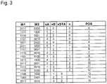
- FIG. 3 shows a diagram for determining the position POS from the read bit pattern (words) using the specific example.
- angle coding 1 can be supplemented by another track or several further tracks with absolute codes or with incremental divisions.
- an incremental track 4 in parallel, ie concentrically, to the tracks with the code sequences A, B.
- the graduation period of this incremental track 4 is advantageously a fraction of the width of a code element of the code sequences A, B. Within an angle sector of a code element, a number greater than or equal to 1 incremental graduation periods is advantageously arranged.
- the incremental graduation 4 is scanned by means of a further, not shown, detector unit, which generates in a known manner a plurality of mutually phase-shifted incremental signals.
- the angle coding 10 is in turn given by the lengths L A and L B of the code sequences A and B, where L A ⁇ L B and L A and L B is an integer. Since the code elements all enclose the same angle sector, the lengths L A and L B are again defined as the number of code elements of the corresponding code sequence A, B.
- the total position POS is here by means of the calculation rules R 1 and R 2 according to the FIG. 6 calculated.
- At the joint ST at least one of the code sequences A, B is cut off and thus the cyclical continuation of at least one of the code sequences (here the code sequence A) is interrupted.
- This area via this junction ST requires separate treatment with at least one separate table, because the bit patterns generated during the sampling via this junction ST are not present in the tables T A and / or T B.
- code sequences A and B are given by: Code sequence A: A 0 A 1 A 2 A 3 A 4 Code sequence B: B 0 B 1 B 2 B 3
- Tables T A and T B are then given by: Table T ⁇ sub> A ⁇ / sub>: for code sequence A Bitpattern Word w Partial position x A A 0 A 1 A 2 A 3 W A0 0 A 1 A 2 A 3 A 4 W A1 1 A 2 A 3 A 4 A 0 W A2 2 A 3 A 4 A 0 A 1 W A3 3 A 4 A 0 A 1 A 2 W A4 4 Bitpattern Word w Partial position x B B 0 B 1 B 2 B 3 W B0 0 B 1 B 2 B 3 B 0 W B1 1 B 2 B 3 B 0 B 1 W B2 2 B 3 B 0 B 1 B 2 W B3 3 3 3 3
- the code sequence A is interrupted at the joint ST.
- the code sequence A now dive when crossing the joint ST with the detector array 20 new bit patterns that do not occur in the table T A.
- the bit A 0 is not followed by A 1 , but again A 0 and then only A 1 .
- the new positions of the code sequence A at the joint ST can be summarized in a new table T STA ("ST" for joint; "A" for the code sequence A).
- calculation rules R1, R2, R3 and R4 for determining the position POS are in FIG. 6 It should be noted that these calculation rules R1, R2, R3 and R4 are given by way of example only, since other relationships may be used here as well.
- Code sequence A 01111
- Code sequence B 0100
- FIG. 7 1 is a diagram for determining the position POS from read bit patterns (words) w using the example of the second angle coding 10.
- words read bit patterns
- FIG. 5 In the second and third columns, those from the words w follow FIG. 5 detected words w1 and w2.
- the six further columns show the query as to whether the words w1 and w2 are found in the tables T A , T B , T STA .
- a "1" defines it found.
- the next column labeled "RV" defines the calculation rule R1, R2, R3 and R4 to be used.
- the following three columns show the subpositions x A , x B and x STA .
- the next column contains the one after the in FIG. 6 calculated value "n".
- the last column now contains the position POS calculated according to the corresponding calculation rules R1, R2, R3 or R4.
- the decoding device 3, 30 is advantageously formed as an ASIC, wherein the required tables T, so the required value inventories, each hardwired in the manufacture of the ASIC's are formed.
- the tables T or value stores can also be stored in read-only memories, such as EPROM.
- a mixed form of memory is particularly advantageous, on the one hand rapid access to the memory data, ie the value stores, being achieved and, on the other hand, rapid adaptation to the intended use.
- This is carried out by on the one hand the value stock T A , T B for the code sequences A and B and their cyclic sequels is hard wired executed and additionally a still programmable memory after the mask is provided, in this programmable memory of the individually required value store T ST , T STA of the shock ST is stored, so the tables T ST and T STA .
- the programmable memory is a read-only memory and is designed, for example, as an EPROM.
- the tables T ST and T STA can be fixed in the manufacture of the angle measuring device, so stored. Alternatively, the tables T ST and T STA can also be generated and stored automatically by means of a predetermined formation specification, or the generation is carried out by means of a calibration run in which each sampled bit pattern (word) is assigned and stored a position.
- the absolute angle coding 10 As in FIG. 4 shown schematically, the absolute angle coding 10 according to the example of FIG. 1 be supplemented by an incremental 40.
- a number advantageously equal to or greater than 1, incremental graduation periods is again arranged within an angle sector of a code element.
- the invention can be used particularly advantageously in the optical scanning principle, since optically scannable angle coding 1, 10 is possible with a maximum various positions over 360 ° (one revolution of the angle coding 1, 10) can be reproduced produced and thus a particularly high-resolution position measurement is possible.
- the detector arrangement 2, 20 and the decoding device 3, 30 may be housed together in an opto-ASIC.
- the invention is not limited to the optical sensing principle, but also in magnetic, inductive and capacitive sensing principles used.
Landscapes
- Physics & Mathematics (AREA)
- General Physics & Mathematics (AREA)
- Transmission And Conversion Of Sensor Element Output (AREA)
Claims (13)
- Codeur d'angle absolu, comportant plusieurs séquences de code (A, B) agencées sur 360° qui, en combinaison, codent de manière unique et absolue les 360°, parmi lesquelles
une première séquence de code (A) de longueur LA, constituée d'une série d'éléments de code, délimite un premier secteur angulaire, est agencée consécutivement de multiples fois, et est également prolongée cycliquement de multiples fois,
une deuxième séquence de code (B) de longueur LB, constituée d'une série d'éléments de code, délimite un deuxième secteur angulaire, est agencée consécutivement de multiples fois, et est également prolongée cycliquement de multiples fois, dans lequel la longueur LA de la première séquence de code (A) est le nombre entier des éléments de code de la première séquence de code et
la longueur LB de la deuxième séquence de code (B) est le nombre entier des éléments de code de la deuxième séquence de code (B), et dans lequel
le premier secteur angulaire est différent du deuxième secteur angulaire, en ce sens que la longueur LA de la première séquence de code (A) est différente de la longueur LB de la deuxième séquence de code (B),
au moins l'une des séquences de code (A, B) n'est réalisée que partiellement sur les 360° et forme un point de jonction (ST) avec la séquence de code suivante (A, B), et
les éléments de code de la première séquence de code (A) et de la deuxième séquence de code (B) délimitent des secteurs angulaires identiques. - Codeur d'angle absolu selon la revendication 1, caractérisé en ce que la longueur LA de la première séquence de code (A) diffère de 1 de la longueur LB de la deuxième séquence de code (B).
- Codeur d'angle absolu selon l'une quelconque des revendications 1 à 2 précédentes, caractérisé en ce que la première séquence de code (A) est disposée dans une première piste et en ce que la deuxième séquence de code (B) est disposée dans une autre piste qui s'étend concentriquement par rapport à la première piste.
- Codeur d'angle absolu selon la revendication 3, caractérisé en ce que des nombres identiques
M1 < KGV(LA, LB) d'éléments de code sont agencés sur 360° dans la première piste ainsi que dans l'autre piste, avec
KGV(LA, LB) = plus petit commun multiple de LA et LB,
LA = nombre entier des éléments de code de la première séquence de code (A),
LB = nombre entier des éléments de code de la deuxième séquence de code (B). - Codeur d'angle absolu selon la revendication 4, caractérisé en ce que le nombre est donné par M1 = 2k, avec k>4 et k étant un nombre entier.
- Codeur d'angle absolu selon l'une quelconque des revendications 1 à 2 précédentes, caractérisé en ce que la première séquence de code (A) et la deuxième séquence de code (B) sont agencées dans une piste commune, en ce sens qu'une partie de la première séquence (A) et qu'une partie de la deuxième séquence de séquence de code (B) sont respectivement disposées de manière alternée.
- Codeur d'angle absolu selon la revendication 6, caractérisé en ce qu'un nombre
M2 < 2*KGV(LA, LB) d'éléments de code sont agencés sur 360°, avec
KGV(LA, LB) = plus petit commun multiple de LA et LB,
LA = nombre entier des éléments de code de la première séquence de code (A),
LB = nombre entier des éléments de code de la deuxième séquence de code (B). - Codeur d'angle absolu selon la revendication 7, caractérisé en ce que le nombre est donné par M2 = 2k, avec k>4 et k étant un nombre entier.
- Codeur d'angle absolu selon l'une quelconque des revendications précédentes, caractérisé en ce qu'au moins une piste incrémentielle (4, 40) est agencée concentriquement par rapport au codeur d'angle absolu (1, 10).
- Codeur d'angle absolu selon la revendication 9, caractérisé en ce qu'une piste incrémentielle unique (4, 40) est agencée concentriquement par rapport au codeur d'angle absolu (1, 10) et en ce qu'un nombre entier supérieur ou égal à 1 de périodes de division incrémentielles est agencé à l'intérieur d'un élément de code.
- Dispositif de mesure d'angle absolu comportant un codeur d'angle (1, 10) selon l'une quelconque des revendications 1 à 10, et
un système détecteur (2, 20) destiné à échantillonner les première et deuxième séquences de code (A, B) du codeur d'angle (1, 10) et à générer des mots de code (w), et
un dispositif de décodage (3, 30) destiné à décoder les mots de code (w) et à générer des valeurs de position (POS). - Dispositif de mesure d'angle absolu selon la revendication 11, caractérisé en ce que le dispositif de décodage (3, 30) comporte une première réserve de valeurs (TA) permettant de décoder une première série de mots de code (wA), laquelle séquence se produit lors de l'échantillonnage de l'une des premières séquences de code (A) ainsi que de leur prolongement cyclique, et
le dispositif de décodage (3, 30) comporte une deuxième réserve de valeurs (TB) permettant de décoder une deuxième série de mots de code (wB), laquelle séquence se produit respectivement lors de l'échantillonnage de l'une des deuxièmes séquences de code (B) ainsi que de leur prolongement cyclique, et
le dispositif de décodage (30) comporte une autre réserve de valeurs (TSTA, TST) qui est appropriée pour le décodage des points de jonction (ST) de la première séquence de code (A) et/ou de la deuxième séquence de code (B). - Dispositif de mesure d'angle absolu selon la revendication 12, caractérisé en ce que l'autre réserve de valeurs (TSTA, TST) est stockée dans une mémoire morte programmable et en ce que la première réserve de valeurs (TA) ainsi que la deuxième réserve de valeurs (TB) sont présentes de manière câblée.
Applications Claiming Priority (2)
| Application Number | Priority Date | Filing Date | Title |
|---|---|---|---|
| DE102008053986A DE102008053986A1 (de) | 2008-10-30 | 2008-10-30 | Absolute Winkelcodierung und Winkelmessvorrichtung |
| PCT/EP2009/007043 WO2010049049A1 (fr) | 2008-10-30 | 2009-10-01 | Dispositif de mesure de position absolue |
Publications (2)
| Publication Number | Publication Date |
|---|---|
| EP2340417A1 EP2340417A1 (fr) | 2011-07-06 |
| EP2340417B1 true EP2340417B1 (fr) | 2017-09-06 |
Family
ID=41600704
Family Applications (1)
| Application Number | Title | Priority Date | Filing Date |
|---|---|---|---|
| EP09778793.1A Active EP2340417B1 (fr) | 2008-10-30 | 2009-10-01 | Dispositif de mesure de position absolue |
Country Status (7)
| Country | Link |
|---|---|
| US (1) | US20110218761A1 (fr) |
| EP (1) | EP2340417B1 (fr) |
| JP (1) | JP5425209B2 (fr) |
| CN (1) | CN102203561B (fr) |
| DE (1) | DE102008053986A1 (fr) |
| ES (1) | ES2650475T3 (fr) |
| WO (1) | WO2010049049A1 (fr) |
Families Citing this family (8)
| Publication number | Priority date | Publication date | Assignee | Title |
|---|---|---|---|---|
| ES2546989T3 (es) * | 2012-06-13 | 2015-09-30 | Dr. Johannes Heidenhain Gmbh | Dispositivo de medición de posición |
| DE102012216854A1 (de) * | 2012-09-20 | 2014-03-20 | Dr. Johannes Heidenhain Gmbh | Positionsmessgerät und Verfahren zu dessen Betrieb |
| EP2725325B1 (fr) * | 2012-10-26 | 2019-12-11 | Robert Bosch Gmbh | Système de mesure de position |
| DE102013222197A1 (de) * | 2013-10-31 | 2015-04-30 | Dr. Johannes Heidenhain Gmbh | Positionsmesseinrichtung |
| EP3021088B1 (fr) * | 2014-11-12 | 2018-03-07 | Balluff GmbH | Système de mesure de longueur incrémental et son procédé de fonctionnement |
| WO2021144966A1 (fr) | 2020-01-17 | 2021-07-22 | ヤマハ発動機株式会社 | Rotor de mécanisme de régulation de rotation, et actionneur |
| WO2021144965A1 (fr) * | 2020-01-17 | 2021-07-22 | ヤマハ発動機株式会社 | Codeur absolu et actionneur comprenant un codeur absolu |
| DE102023118535A1 (de) * | 2023-07-13 | 2025-01-16 | Sick Ag | Gebervorrichtung |
Family Cites Families (12)
| Publication number | Priority date | Publication date | Assignee | Title |
|---|---|---|---|---|
| GB2076147B (en) * | 1980-05-15 | 1984-07-11 | Ferranti Ltd | Position encoder |
| US4628298A (en) * | 1984-06-22 | 1986-12-09 | Bei Motion Systems Company, Inc. | Chain code encoder |
| US4947166A (en) * | 1988-02-22 | 1990-08-07 | Dynamics Research Corporation | Single track absolute encoder |
| GB8826114D0 (en) * | 1988-11-08 | 1988-12-14 | The Technology Partnership Ltd | Decoding of random sequences |
| US5135081A (en) * | 1991-05-01 | 1992-08-04 | United States Elevator Corp. | Elevator position sensing system using coded vertical tape |
| US5739775A (en) * | 1993-07-22 | 1998-04-14 | Bourns, Inc. | Digital input and control device |
| US5457371A (en) * | 1993-08-17 | 1995-10-10 | Hewlett Packard Company | Binary locally-initializing incremental encoder |
| JP3816679B2 (ja) * | 1998-09-17 | 2006-08-30 | 株式会社東海理化電機製作所 | 回転角度検出装置 |
| US7034283B2 (en) * | 2003-03-05 | 2006-04-25 | Raytheon Company | Absolute incremental position encoder and method |
| GB0412122D0 (en) * | 2004-05-29 | 2004-06-30 | Farrow Michael J | Magnetic encoder |
| JP4924878B2 (ja) * | 2006-11-06 | 2012-04-25 | 株式会社ニコン | アブソリュートエンコーダ |
| CN100476366C (zh) * | 2007-09-19 | 2009-04-08 | 苏州一光仪器有限公司 | 单码道绝对式角度编码度盘及采用该度盘的编码器 |
-
2008
- 2008-10-30 DE DE102008053986A patent/DE102008053986A1/de not_active Withdrawn
-
2009
- 2009-10-01 US US13/126,605 patent/US20110218761A1/en not_active Abandoned
- 2009-10-01 JP JP2011533563A patent/JP5425209B2/ja active Active
- 2009-10-01 CN CN200980143346.4A patent/CN102203561B/zh active Active
- 2009-10-01 EP EP09778793.1A patent/EP2340417B1/fr active Active
- 2009-10-01 WO PCT/EP2009/007043 patent/WO2010049049A1/fr not_active Ceased
- 2009-10-01 ES ES09778793.1T patent/ES2650475T3/es active Active
Non-Patent Citations (1)
| Title |
|---|
| None * |
Also Published As
| Publication number | Publication date |
|---|---|
| EP2340417A1 (fr) | 2011-07-06 |
| JP2012507015A (ja) | 2012-03-22 |
| JP5425209B2 (ja) | 2014-02-26 |
| US20110218761A1 (en) | 2011-09-08 |
| CN102203561A (zh) | 2011-09-28 |
| WO2010049049A1 (fr) | 2010-05-06 |
| CN102203561B (zh) | 2014-07-16 |
| ES2650475T3 (es) | 2018-01-18 |
| DE102008053986A1 (de) | 2010-05-06 |
Similar Documents
| Publication | Publication Date | Title |
|---|---|---|
| EP2340417B1 (fr) | Dispositif de mesure de position absolue | |
| EP2342540B1 (fr) | Codage d'angle absolu et dispositif de mesure d'angle | |
| DE10296644B4 (de) | Absolute Positionsmessung | |
| EP1821073B1 (fr) | Dispositif de mesure de position | |
| EP1329696A1 (fr) | Détecteur de position absolue avec échelle | |
| EP4242595B1 (fr) | Dispositif et procédé de détermination de position, de longueur ou d'angle | |
| EP2561319A1 (fr) | Dispositif de détection de position et procédé de fabrication d'un agencement de marquage pour un dispositif de détection de position | |
| EP1206684B1 (fr) | Dispositif de mesure de position | |
| EP2342539B1 (fr) | Dispositif de mesure de position absolue | |
| EP1514375B1 (fr) | Procede et dispositif de codage et decodage d'une sequence de donnees numeriques | |
| EP2725325B1 (fr) | Système de mesure de position | |
| EP2271897B1 (fr) | Dispositif de mesure angulaire et série comportant ce dispositif | |
| EP2340418B1 (fr) | Code d'une position absolu et dispositif de mesure de positions | |
| DE102006010161B4 (de) | Codestruktur für eine Positionsmesseinrichtung und Positionsmesseinrichtung mit einer solchen Codestruktur | |
| EP4492013B1 (fr) | Dispositif de détection | |
| DE102021110583B4 (de) | Gebervorrichtung und Verfahren zur Bestimmung einer Absolutposition | |
| EP1770375B1 (fr) | Dispositif de mesure de position comprenant deux echelles de mesure dont les pistes codées se chevauchent mutuellement | |
| EP1744127B1 (fr) | Procédé destiné à la détermination de la position angulaire absolue du volant d'un véhicule automobile | |
| DE102019103465A1 (de) | Positionsmessvorrichtung zur Messung einer Absolutposition | |
| DE19818654A1 (de) | Sensoreinheit für Gebersysteme | |
| EP0707384A1 (fr) | Dispositif de mesure de position | |
| DE2556803B1 (de) | Verfahren zur Datenkompression binaer codierter Bildsignale |
Legal Events
| Date | Code | Title | Description |
|---|---|---|---|
| PUAI | Public reference made under article 153(3) epc to a published international application that has entered the european phase |
Free format text: ORIGINAL CODE: 0009012 |
|
| 17P | Request for examination filed |
Effective date: 20110530 |
|
| AK | Designated contracting states |
Kind code of ref document: A1 Designated state(s): AT BE BG CH CY CZ DE DK EE ES FI FR GB GR HR HU IE IS IT LI LT LU LV MC MK MT NL NO PL PT RO SE SI SK SM TR |
|
| AX | Request for extension of the european patent |
Extension state: AL BA RS |
|
| DAX | Request for extension of the european patent (deleted) | ||
| GRAP | Despatch of communication of intention to grant a patent |
Free format text: ORIGINAL CODE: EPIDOSNIGR1 |
|
| INTG | Intention to grant announced |
Effective date: 20170621 |
|
| GRAS | Grant fee paid |
Free format text: ORIGINAL CODE: EPIDOSNIGR3 |
|
| GRAA | (expected) grant |
Free format text: ORIGINAL CODE: 0009210 |
|
| AK | Designated contracting states |
Kind code of ref document: B1 Designated state(s): AT BE BG CH CY CZ DE DK EE ES FI FR GB GR HR HU IE IS IT LI LT LU LV MC MK MT NL NO PL PT RO SE SI SK SM TR |
|
| REG | Reference to a national code |
Ref country code: GB Ref legal event code: FG4D Free format text: NOT ENGLISH |
|
| REG | Reference to a national code |
Ref country code: CH Ref legal event code: EP Ref country code: AT Ref legal event code: REF Ref document number: 926367 Country of ref document: AT Kind code of ref document: T Effective date: 20170915 |
|
| REG | Reference to a national code |
Ref country code: CH Ref legal event code: NV Representative=s name: ICB INGENIEURS CONSEILS EN BREVETS SA, CH |
|
| REG | Reference to a national code |
Ref country code: IE Ref legal event code: FG4D Free format text: LANGUAGE OF EP DOCUMENT: GERMAN |
|
| REG | Reference to a national code |
Ref country code: DE Ref legal event code: R096 Ref document number: 502009014342 Country of ref document: DE |
|
| REG | Reference to a national code |
Ref country code: NL Ref legal event code: MP Effective date: 20170906 |
|
| REG | Reference to a national code |
Ref country code: ES Ref legal event code: FG2A Ref document number: 2650475 Country of ref document: ES Kind code of ref document: T3 Effective date: 20180118 |
|
| REG | Reference to a national code |
Ref country code: LT Ref legal event code: MG4D |
|
| PG25 | Lapsed in a contracting state [announced via postgrant information from national office to epo] |
Ref country code: LT Free format text: LAPSE BECAUSE OF FAILURE TO SUBMIT A TRANSLATION OF THE DESCRIPTION OR TO PAY THE FEE WITHIN THE PRESCRIBED TIME-LIMIT Effective date: 20170906 Ref country code: NO Free format text: LAPSE BECAUSE OF FAILURE TO SUBMIT A TRANSLATION OF THE DESCRIPTION OR TO PAY THE FEE WITHIN THE PRESCRIBED TIME-LIMIT Effective date: 20171206 Ref country code: HR Free format text: LAPSE BECAUSE OF FAILURE TO SUBMIT A TRANSLATION OF THE DESCRIPTION OR TO PAY THE FEE WITHIN THE PRESCRIBED TIME-LIMIT Effective date: 20170906 Ref country code: SE Free format text: LAPSE BECAUSE OF FAILURE TO SUBMIT A TRANSLATION OF THE DESCRIPTION OR TO PAY THE FEE WITHIN THE PRESCRIBED TIME-LIMIT Effective date: 20170906 Ref country code: FI Free format text: LAPSE BECAUSE OF FAILURE TO SUBMIT A TRANSLATION OF THE DESCRIPTION OR TO PAY THE FEE WITHIN THE PRESCRIBED TIME-LIMIT Effective date: 20170906 |
|
| PG25 | Lapsed in a contracting state [announced via postgrant information from national office to epo] |
Ref country code: GR Free format text: LAPSE BECAUSE OF FAILURE TO SUBMIT A TRANSLATION OF THE DESCRIPTION OR TO PAY THE FEE WITHIN THE PRESCRIBED TIME-LIMIT Effective date: 20171207 Ref country code: LV Free format text: LAPSE BECAUSE OF FAILURE TO SUBMIT A TRANSLATION OF THE DESCRIPTION OR TO PAY THE FEE WITHIN THE PRESCRIBED TIME-LIMIT Effective date: 20170906 Ref country code: BG Free format text: LAPSE BECAUSE OF FAILURE TO SUBMIT A TRANSLATION OF THE DESCRIPTION OR TO PAY THE FEE WITHIN THE PRESCRIBED TIME-LIMIT Effective date: 20171206 |
|
| PG25 | Lapsed in a contracting state [announced via postgrant information from national office to epo] |
Ref country code: NL Free format text: LAPSE BECAUSE OF FAILURE TO SUBMIT A TRANSLATION OF THE DESCRIPTION OR TO PAY THE FEE WITHIN THE PRESCRIBED TIME-LIMIT Effective date: 20170906 |
|
| PG25 | Lapsed in a contracting state [announced via postgrant information from national office to epo] |
Ref country code: CZ Free format text: LAPSE BECAUSE OF FAILURE TO SUBMIT A TRANSLATION OF THE DESCRIPTION OR TO PAY THE FEE WITHIN THE PRESCRIBED TIME-LIMIT Effective date: 20170906 Ref country code: PL Free format text: LAPSE BECAUSE OF FAILURE TO SUBMIT A TRANSLATION OF THE DESCRIPTION OR TO PAY THE FEE WITHIN THE PRESCRIBED TIME-LIMIT Effective date: 20170906 Ref country code: RO Free format text: LAPSE BECAUSE OF FAILURE TO SUBMIT A TRANSLATION OF THE DESCRIPTION OR TO PAY THE FEE WITHIN THE PRESCRIBED TIME-LIMIT Effective date: 20170906 |
|
| PG25 | Lapsed in a contracting state [announced via postgrant information from national office to epo] |
Ref country code: SK Free format text: LAPSE BECAUSE OF FAILURE TO SUBMIT A TRANSLATION OF THE DESCRIPTION OR TO PAY THE FEE WITHIN THE PRESCRIBED TIME-LIMIT Effective date: 20170906 Ref country code: IS Free format text: LAPSE BECAUSE OF FAILURE TO SUBMIT A TRANSLATION OF THE DESCRIPTION OR TO PAY THE FEE WITHIN THE PRESCRIBED TIME-LIMIT Effective date: 20180106 Ref country code: EE Free format text: LAPSE BECAUSE OF FAILURE TO SUBMIT A TRANSLATION OF THE DESCRIPTION OR TO PAY THE FEE WITHIN THE PRESCRIBED TIME-LIMIT Effective date: 20170906 Ref country code: SM Free format text: LAPSE BECAUSE OF FAILURE TO SUBMIT A TRANSLATION OF THE DESCRIPTION OR TO PAY THE FEE WITHIN THE PRESCRIBED TIME-LIMIT Effective date: 20170906 |
|
| REG | Reference to a national code |
Ref country code: DE Ref legal event code: R097 Ref document number: 502009014342 Country of ref document: DE |
|
| PG25 | Lapsed in a contracting state [announced via postgrant information from national office to epo] |
Ref country code: MC Free format text: LAPSE BECAUSE OF FAILURE TO SUBMIT A TRANSLATION OF THE DESCRIPTION OR TO PAY THE FEE WITHIN THE PRESCRIBED TIME-LIMIT Effective date: 20170906 |
|
| PLBE | No opposition filed within time limit |
Free format text: ORIGINAL CODE: 0009261 |
|
| STAA | Information on the status of an ep patent application or granted ep patent |
Free format text: STATUS: NO OPPOSITION FILED WITHIN TIME LIMIT |
|
| REG | Reference to a national code |
Ref country code: IE Ref legal event code: MM4A |
|
| REG | Reference to a national code |
Ref country code: FR Ref legal event code: ST Effective date: 20180629 |
|
| PG25 | Lapsed in a contracting state [announced via postgrant information from national office to epo] |
Ref country code: DK Free format text: LAPSE BECAUSE OF FAILURE TO SUBMIT A TRANSLATION OF THE DESCRIPTION OR TO PAY THE FEE WITHIN THE PRESCRIBED TIME-LIMIT Effective date: 20170906 Ref country code: LU Free format text: LAPSE BECAUSE OF NON-PAYMENT OF DUE FEES Effective date: 20171001 |
|
| 26N | No opposition filed |
Effective date: 20180607 |
|
| REG | Reference to a national code |
Ref country code: BE Ref legal event code: MM Effective date: 20171031 |
|
| PG25 | Lapsed in a contracting state [announced via postgrant information from national office to epo] |
Ref country code: SI Free format text: LAPSE BECAUSE OF FAILURE TO SUBMIT A TRANSLATION OF THE DESCRIPTION OR TO PAY THE FEE WITHIN THE PRESCRIBED TIME-LIMIT Effective date: 20170906 Ref country code: FR Free format text: LAPSE BECAUSE OF NON-PAYMENT OF DUE FEES Effective date: 20171106 Ref country code: BE Free format text: LAPSE BECAUSE OF NON-PAYMENT OF DUE FEES Effective date: 20171031 |
|
| PG25 | Lapsed in a contracting state [announced via postgrant information from national office to epo] |
Ref country code: MT Free format text: LAPSE BECAUSE OF FAILURE TO SUBMIT A TRANSLATION OF THE DESCRIPTION OR TO PAY THE FEE WITHIN THE PRESCRIBED TIME-LIMIT Effective date: 20170906 |
|
| PG25 | Lapsed in a contracting state [announced via postgrant information from national office to epo] |
Ref country code: IE Free format text: LAPSE BECAUSE OF NON-PAYMENT OF DUE FEES Effective date: 20171001 |
|
| REG | Reference to a national code |
Ref country code: AT Ref legal event code: MM01 Ref document number: 926367 Country of ref document: AT Kind code of ref document: T Effective date: 20171001 |
|
| PG25 | Lapsed in a contracting state [announced via postgrant information from national office to epo] |
Ref country code: AT Free format text: LAPSE BECAUSE OF NON-PAYMENT OF DUE FEES Effective date: 20171001 |
|
| PG25 | Lapsed in a contracting state [announced via postgrant information from national office to epo] |
Ref country code: HU Free format text: LAPSE BECAUSE OF FAILURE TO SUBMIT A TRANSLATION OF THE DESCRIPTION OR TO PAY THE FEE WITHIN THE PRESCRIBED TIME-LIMIT; INVALID AB INITIO Effective date: 20091001 |
|
| PG25 | Lapsed in a contracting state [announced via postgrant information from national office to epo] |
Ref country code: CY Free format text: LAPSE BECAUSE OF NON-PAYMENT OF DUE FEES Effective date: 20170906 |
|
| PG25 | Lapsed in a contracting state [announced via postgrant information from national office to epo] |
Ref country code: MK Free format text: LAPSE BECAUSE OF FAILURE TO SUBMIT A TRANSLATION OF THE DESCRIPTION OR TO PAY THE FEE WITHIN THE PRESCRIBED TIME-LIMIT Effective date: 20170906 |
|
| PG25 | Lapsed in a contracting state [announced via postgrant information from national office to epo] |
Ref country code: TR Free format text: LAPSE BECAUSE OF FAILURE TO SUBMIT A TRANSLATION OF THE DESCRIPTION OR TO PAY THE FEE WITHIN THE PRESCRIBED TIME-LIMIT Effective date: 20170906 |
|
| PG25 | Lapsed in a contracting state [announced via postgrant information from national office to epo] |
Ref country code: PT Free format text: LAPSE BECAUSE OF FAILURE TO SUBMIT A TRANSLATION OF THE DESCRIPTION OR TO PAY THE FEE WITHIN THE PRESCRIBED TIME-LIMIT Effective date: 20170906 |
|
| REG | Reference to a national code |
Ref country code: CH Ref legal event code: U11 Free format text: ST27 STATUS EVENT CODE: U-0-0-U10-U11 (AS PROVIDED BY THE NATIONAL OFFICE) Effective date: 20251101 |
|
| PGFP | Annual fee paid to national office [announced via postgrant information from national office to epo] |
Ref country code: DE Payment date: 20251021 Year of fee payment: 17 |
|
| REG | Reference to a national code |
Ref country code: CH Ref legal event code: R17 Free format text: ST27 STATUS EVENT CODE: U-0-0-R10-R17 (AS PROVIDED BY THE NATIONAL OFFICE) Effective date: 20260108 |
|
| PGFP | Annual fee paid to national office [announced via postgrant information from national office to epo] |
Ref country code: GB Payment date: 20251022 Year of fee payment: 17 |
|
| PGFP | Annual fee paid to national office [announced via postgrant information from national office to epo] |
Ref country code: IT Payment date: 20251024 Year of fee payment: 17 |
|
| PGFP | Annual fee paid to national office [announced via postgrant information from national office to epo] |
Ref country code: CH Payment date: 20251101 Year of fee payment: 17 |
|
| PGFP | Annual fee paid to national office [announced via postgrant information from national office to epo] |
Ref country code: ES Payment date: 20251210 Year of fee payment: 17 |