EP2340708A1 - Geflügelsammeleinrichtung - Google Patents
Geflügelsammeleinrichtung Download PDFInfo
- Publication number
- EP2340708A1 EP2340708A1 EP10197103A EP10197103A EP2340708A1 EP 2340708 A1 EP2340708 A1 EP 2340708A1 EP 10197103 A EP10197103 A EP 10197103A EP 10197103 A EP10197103 A EP 10197103A EP 2340708 A1 EP2340708 A1 EP 2340708A1
- Authority
- EP
- European Patent Office
- Prior art keywords
- conveyor belt
- vehicle
- fowl
- belt
- unloading
- Prior art date
- Legal status (The legal status is an assumption and is not a legal conclusion. Google has not performed a legal analysis and makes no representation as to the accuracy of the status listed.)
- Withdrawn
Links
- 244000144977 poultry Species 0.000 title 1
- 238000005303 weighing Methods 0.000 claims abstract description 15
- 230000004888 barrier function Effects 0.000 claims description 25
- 238000011144 upstream manufacturing Methods 0.000 claims description 3
- 241001465754 Metazoa Species 0.000 description 10
- 241000287828 Gallus gallus Species 0.000 description 5
- 235000013330 chicken meat Nutrition 0.000 description 5
- 241001417527 Pempheridae Species 0.000 description 4
- 239000000463 material Substances 0.000 description 3
- 238000005259 measurement Methods 0.000 description 3
- 238000000034 method Methods 0.000 description 3
- 241001124569 Lycaenidae Species 0.000 description 2
- 239000002828 fuel tank Substances 0.000 description 2
- 238000009309 intensive farming Methods 0.000 description 2
- 235000013372 meat Nutrition 0.000 description 2
- 238000003307 slaughter Methods 0.000 description 2
- 238000009825 accumulation Methods 0.000 description 1
- 230000003466 anti-cipated effect Effects 0.000 description 1
- 230000005540 biological transmission Effects 0.000 description 1
- 238000002485 combustion reaction Methods 0.000 description 1
- 238000010276 construction Methods 0.000 description 1
- 238000009313 farming Methods 0.000 description 1
- 239000000446 fuel Substances 0.000 description 1
- 244000144972 livestock Species 0.000 description 1
- 230000001681 protective effect Effects 0.000 description 1
Images






Classifications
-
- A—HUMAN NECESSITIES
- A01—AGRICULTURE; FORESTRY; ANIMAL HUSBANDRY; HUNTING; TRAPPING; FISHING
- A01K—ANIMAL HUSBANDRY; AVICULTURE; APICULTURE; PISCICULTURE; FISHING; REARING OR BREEDING ANIMALS, NOT OTHERWISE PROVIDED FOR; NEW BREEDS OF ANIMALS
- A01K45/00—Other aviculture appliances, e.g. devices for determining whether a bird is about to lay
- A01K45/005—Harvesting or transport of poultry
Definitions
- the present invention relates to a vehicle for gathering fowl (for example, chickens or similar animals) from the ground and placing them in a cage.
- fowl for example, chickens or similar animals
- the live animals must be collected (without harming them) from the shed where they were raised and taken to the next treatment stages, typically slaughtering.
- the animals collected are typically put inside cages. However, the animals collected may also not be caged but taken to another farm shed or put inside another type of container or on a conveyor belt.
- Gathering (and caging) operations are typically carried out using particular machines, commonly known as “fowl harvesters”.
- the machines are called “chicken harvesters”.
- Patent no. EP0713642 describes a system for loading fowl into containers.
- the patent also describes a separate capturing vehicle that, moving independently from the system, can capture live fowl and take them to the receiving location.
- the capturing vehicle according to patent no. EP0713642 includes a tractor and two conveyor sets on the sides of the tractor. Each conveyor set includes an inclined conveyor and an accumulating conveyor.
- Patent application no. IT2007A000331 describes a fowl-gathering vehicle that comprises: a frame; wheels or tracks to support the frame above the ground; a gathering conveyor belt to collect the fowl from the ground and an accumulating conveyor belt that receives the fowl from the gathering conveyor belt and that runs in the same direction of the gathering conveyor belt, wherein the speed of the gathering conveyor belt, when picking up the fowl, is greater than the speed of the accumulating conveyor belt.
- the vehicle of patent application no. IT2007A000331 is very efficient, can be used inside small areas and has a high chicken-loading capacity.
- a vehicle which gathers fowl from the ground and carries them to a place of unloading, for example a cage.
- the vehicle comprises: a main frame; wheels or tracks to support the main frame above the ground; an accumulating conveyor belt to carry the fowl in a first direction (which can be, essentially, the longitudinal direction of the vehicle); and an unloading conveyor belt that receives the fowl from the accumulating conveyor belt and carries the fowl received towards a place of unloading.
- the unloading conveyor belt carries the fowl in a second direction.
- the second direction may be at an angle with respect to the first direction.
- the vehicle also comprises a belt-supporting structure to support the accumulating conveyor belt and the unloading conveyor belt.
- the vehicle may also comprise a counterframe.
- the belt-supporting structure is at least partially raisable respect to the counterframe.
- the vehicle may also advantageously comprise a weighing device placed between the main frame and the counterframe for weighing the fowl carried on the conveyor belts.
- the weighing device comprises load cells.
- the weighing device comprises two front load cells and two rear load cells placed symmetrically to a centre line of the vehicle.
- the main frame comprises crossbars, each of which crossbars comprises an end fastening block on which to fasten the load cells.
- the belt-supporting structure is pivotally hinged to the counterframe at a front part of the vehicle.
- the vehicle also comprises a lifting device for raising the belt-supporting structure respect to the counterframe at its rear part.
- the counterframe may comprise two longitudinal crossbars and the belt-supporting structure may be pivotally hinged to the longitudinal crossbars at a front part of them.
- the vehicle comprises a barrier between said accumulating conveyor belt and said unloading conveyor belt.
- the vehicle comprises a further barrier in an intermediate position of said accumulating conveyor belt.
- Said further barrier may be operated manually or by weight data referring to the weight of the fowl accumulated on said second conveyor belt, upstream of said further barrier.
- the unloading conveyor belt is preferably operated to unload fowl towards the right side and/or left side of the vehicle.
- the vehicle also comprises a gathering conveyor belt to collect the fowl from the ground and carry them to the accumulating conveyor belt.
- the second direction is substantially perpendicular to the first direction.
- the vehicle also comprises a wheel lifting device to raise said wheels or said tracks respect to the main frame.
- the vehicle also comprises a driving arrangement fixed to said belt-supporting structure and raisable with it. Between the driving arrangement and the accumulating conveyor belt sufficient space is provided for the fowl to pass.
- the term "speed" referred to a conveyor belt shall be understood to mean the length (for example in metres [m]) of conveyor belt that, in fully operational conditions, travels by during a predetermined unit of time (for example one minute [min]). Therefore, a speed of 20 m/min means that in one minute, in fully operational conditions, a length of twenty metres of belt travels by a fixed point.
- the present inventors have carried out speed measurements using a digital tachometer manufactured by Borletti, model "Digital Tachometer t20". This device, or a similar one, can be used to measure the speed of conveyor belts.
- the right side of the vehicle is the right side when the vehicle is viewed from the front.
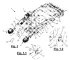
- Figure 1 shows an embodiment of the vehicle relating to the present invention.
- Reference number 1 refers to the vehicle in its entirety.
- the fowl that can be gathered by the vehicle 1 are chickens.
- the vehicle 1 comprises a main frame 2. To the main frame 2 are pivotally attached front wheels 31 and rear wheels 32.
- the front and rear wheels are operated by corresponding hydraulic drive motors (not shown).
- the hydraulic drive motors are connected to a pressurized-oil power supply with a pump controlled by an internal-combustion engine 4, for example an engine which is petrol or diesel fueled.
- the vehicle 1 is fitted with two front wheels 31, distanced from one another, and two directly coupled rear wheels 32.
- the vehicle can be fitted with crawler tracks.
- the motor 4 is preferably housed and sheltered in a protective, box-shaped casing (not shown) to prevent the operator and/or the fowl collected from accidentally coming into contact with parts of the motor 4.
- the vehicle 1 may not be equipped with its own motor and be hitched to another motor vehicle, such as a tractor or similar vehicle (not shown).
- another motor vehicle such as a tractor or similar vehicle (not shown).
- a driving arrangement 5 comprising a steering device 51 to direct the vehicle 1 in the direction chosen by the operator.
- the embodiment shown includes a seat 52 with a steering wheel 51 and other driving controls 53 operated by pedal and/or by hand. These controls 53 are not relevant for the purposes of the present invention and shall therefore not be described further.
- the driving arrangement 5, on the other hand, shall be better described below.
- the vehicle 1 also comprises a counterframe 23 supported by the main frame 2.
- the main frame 2 and counterframe 23 shall be described in more detail below.
- the vehicle 1 also comprises a conveyor belt assembly 6 and a conveyor belt-supporting structure 21.
- the conveyor belt assembly 6 preferably comprises three conveyor belts, a first pick-up conveyor belt 61, a second accumulating conveyor belt 62 and a third unloading conveyor belt 63.
- the sides of the second conveyor belt 62 are provided with sideboards 65 forming a channel and preventing the animals collected from falling off the sides.
- the first conveyor belt 61 and the second conveyor belt 62 are aligned.
- the gathering conveyor belt 61 is hinged to the main frame 2 in the front part of the main frame 2.
- Figure 14 shows in outline a hydraulic motor 612 configured to turn a roller (not shown) around an axis 613 and consequently actuate the rotation of the first conveyor belt 61.
- the accumulating conveyor belt 62 and the unloading conveyor belt 63 are supported by the belt-supporting structure 21.
- Said belt-supporting structure 21 is hinged to the counterframe 23 and rotates around an axis that passes through the centres of two holes 231 in the front part of the counterframe 23 ( Figure 14).
- Figure 14 shows only the right part of the counterframe 23 but it is clear that the counterframe 23 is symmetric to the vehicle's centre line.
- the counterframe may consist of a single piece with two transverse members and two longitudinal members connected so to form a rectangular structure.
- the counterframe comprises two longitudinal members 23 (only the right-hand side longitudinal member is shown in Figure 14 ) essentially fastened to the ends of a front crossbar 24F and a rear crossbar 24R of the main frame 2.
- the pick-up conveyor belt 61 is located at the head of the vehicle 1 and, at least in the pick-up configuration, can be inclined down towards the ground.
- the accumulating conveyor belt 62 is located downstream from the pick-up conveyor belt 61.
- the term "downstream" refers to the vehicle 1 in the pick-up configuration.
- the pick-up conveyor belt 61 is preferably a belt made of plastic or similar material wrapped in a closed loop around at least one shaft (drive roller) and one idle roller.
- the accumulating conveyor belt 62 is wrapped in a closed loop around a drive roller and an idle roller.
- intermediate idle rollers or transmission devices are placed between the drive roller and the idle roller around which the accumulating conveyor belt is wrapped, to ensure that the conveyor belt follows a predetermined path.
- the vehicle 1 comprises three hydraulic motors connected to the oil circuit, each one separately driving each conveyor belt 61, 62 and 63.
- the speed of the pick-up conveyor belt 61 is greater than the speed of the accumulating conveyor belt 62.
- the speed of the pick-up conveyor belt 61 in the fowl gathering phase is at least twice the speed of the accumulating conveyor belt 62. More preferably, the speed of the pick-up conveyor belt 61 in the fowl gathering phase is at least three times the speed of the accumulating conveyor belt 62. Even more preferably, the speed of the pick-up conveyor belt 61 in the fowl gathering phase is about four times the speed of the accumulating conveyor belt 62.
- the inventors believe that approximately 15 m/min is a convenient speed for the gathering conveyor belt 61 and that approximately 3 or 4 m/min is a convenient speed for the accumulating conveyor belt 62.
- the unloading conveyor belt 63 configured to receive fowl from the accumulating conveyor belt 62 and direct the fowl towards cages or coops, as described below, is preferably located downstream from the accumulating conveyor belt 62.
- the direction of movement of unloading conveyor belt 63 is perpendicular or essentially perpendicular to the direction of movement of the accumulating conveyor belt.
- the direction of movement of the accumulating conveyor belt 62 is essentially longitudinal to the main frame 2, while the direction of movement of the unloading conveyor belt 63 is at an angle with respect to the direction of the accumulating conveyor belt (for example, transversal), in order to unload the fowl from the sides.
- the unloading of the fowl is done from the right side of the vehicle 1. In another embodiment of the present invention the unloading of the fowl is done from the left side of the vehicle 1. In a particularly advantageous embodiment, the unloading of the fowl can be done from the right side and from the left side.
- the unloading conveyor belt 63 is extensible so that it can extend towards (and if necessary also inside) the cages at the time of unloading.
- Figure 7 shows the mechanism that allows the unloading conveyor belt 63 to extend towards cages placed on the right or left of the vehicle 1.
- the conveyor belt 63 is wrapped in an "S", both right and left, around rollers and/or fixed tubes 631-637, and forms loops. Thanks to hydraulic cylinders 638, 639 the upper level can be extended to the right and/or to the left.
- the rollers 631, 632, 633, 634, 635, 636, 637 that support the unloading conveyor belt 63 can turn clockwise or anticlockwise, depending on which side the operator wants to unload the fowl.
- the vehicle 1 comprises a driving arrangement 5 with a steering wheel 51 or handlebar for steering the vehicle 1 in the direction chosen by the operator, a seat 52 and other driving controls 53.
- the driving seat 5 is fastened to a plate 54 placed above the accumulating conveyor belt 61. Between the plate 54 and the surface of the accumulating conveyor belt 62 there is, preferably, a vertical distance (for example about 30 cm) high enough for the fowl to pass through. In this way, the entire width of the accumulating conveyor belt 62 can be used and the operator has complete visibility and control. This is very useful during both fowl loading and unloading operations.
- a separating barrier 66 is preferably placed between the accumulating conveyor belt 62 and the unloading conveyor belt 63. Said barrier 66 prevents the animals picked-up from accessing the unloading conveyor belt 63.
- the barrier 66 is opened (by lifting or rotating) when the fowl have to pass from the accumulating conveyor belt 62 to the unloading conveyor belt 63.
- an intermediate barrier 661 can be placed at an intermediate distance from the accumulating belt.
- the intermediate barrier 661 is preferably left closed during the initial fowl gathering phase until the first part of the gathering belt (upstream of the intermediate barrier) is essentially filled with fowl.
- the intermediate barrier 661 is then opened so that the fowl accumulated can be passed onto the second section of the accumulating conveyor belt making room for new fowl on the front part of the accumulating conveyor belt.
- At least two rotating sweepers 70 can be envisaged, with tips made of rubber or a similar flexible material.
- an upper transverse sweeper can be applied above the front edge of the gathering conveyor belt.
- the vehicle 1 comprises a fowl weighing system.
- the weighing system is particularly suited for weighing the fowl during the gathering phase and also during the unloading phase, as will be better explained below.
- the weighing system preferably comprises electronic load cells.
- the weighing system preferably comprises three or more load cells.
- four load cells are envisaged, two front load cells 91 fastened to the end blocks 24F1 of the front crossbar 24F of the main frame and two rear load cells 92 fastened to the end blocks 24R1 of the rear crossbar 24R ( Figure 14 ).
- each block 24F1 and 24R1 comprises holes for fastening the body of its respective load cell 91, 92 by means of screws (not shown).
- each longitudinal member 23 comprises a front hole 232 and a rear hole 233 configured, respectively, to receive one of the front load cells 91 and one of the rear load cells 92. Therefore, the counterframe 23 is connected to the main frame 2 through the load cells.
- each crossbar 23 comprises a rear bracket 234, preferably having a downward-curving shape.
- the rear bracket 234 is configured to support the piston rod of a respective hydraulic cylinder 22.
- the body of the hydraulic cylinder 22 is fastened to the belt-supporting structure.
- the hydraulic cylinder 22 can be extended to raise the rear part of the belt-supporting structure, which is hinged to the counterframe 23 at the front thereof.
- the vehicle 1 preferably comprises two hydraulic cylinders 22, one for each longitudinal crossbar 23.
- Each rear bracket 234 ends with a pair of holes 235 to receive a pivot pin for connecting the bracket 234 to the rod of the hydraulic cylinder 22.
- the load cells 91, 92 are preferably configured to detect the weight of the belt-supporting structure 21.
- the weight of said structure including the weight of conveyor belts 62, 63, of the driving arrangement 5 (and of the operator in the driver's seat) and of the motor 4 remains essentially unvaried during the vehicle's operation. Strictly speaking, the weight of the fuel that feeds the motor does change (if the fuel tank is supported by the belt-supporting structure 21), but this change in weight can be considered negligible. Therefore, the only substantial change in weight detected by the load cells is produced by the fowl carried on the conveyor belts 62 and/or 63.
- variable weight means the weight of the fowl on the conveyor belts, in particular on conveyor belts 62 and 63.
- the term “fixed weight” refers essentially to the weight of the structure 21, including the weight of the conveyor belts 62, 63, of the driving arrangement 5, of the operator, of the motor 4 and if necessary of the fuel tank.
- total weight means the sum of the fixed weight and the variable weight. Accordingly, knowing the fixed weight (measured by the load cells before starting the fowl gathering operations), the weight of the fowl can be deduced as being the difference between the total weight and the fixed weight.
- the load cells 91, 92 transmit weight data referring to the weight of the loaded fowl to a displaying device and/or to a computer (not shown).
- the displaying device for example a monitor or a display
- an acoustic device (not shown) provide information on the weight of the fowl loaded and/or unloaded. For example, if it was decided to gather and load fowl amounting to a certain weight (for example 400 kg), the load cells transmit, preferably in real time (that is, as the fowl are being loaded) the weight of the fowl on the accumulating conveyor belt 62 and/or on the unloading conveyor belt 63.
- the operator is alerted (acoustically and/or visually) and can stop gathering.
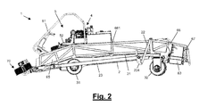
- the gathering conveyor belt 61 is automatically stopped and, if necessary, automatically raised to assume the travelling configuration, described hereunder with reference to Figure 2 .
- the vehicle's operator can be alerted and/or the intermediate barrier 661 can be automatically raised in order to transfer the collected fowl to the second section of the accumulating conveyor belt 62, which is closed off by barrier 66.
- the accumulation preferably occurs in two phases or stages.
- the fowl are loaded according to a preset weight. Since the weight of industrially-bred fowl is often essentially the same, this advantageous feature allows loading the desired number of fowl, within a tolerance interval.
- the accumulating conveyor belt 62 is stopped, to prevent the fowl from piling up against the closed barrier.
- the actual weight of the collected fowl is measured again.
- a software program then divides the total actual weight of the collected fowl by the total number of cages to be filled, in order to distribute the fowl inside the cages as evenly as possible.
- the weight of the remaining fowl is divided by the number of remaining cages, to obtain the theoretical weight of the fowl to put in the second cage.
- the weight of the remaining fowl is again divided by the number of remaining cages to obtain the weight of the fowl to put in the next cage.
- the procedure is repeated iteratively until all the cages are essentially evenly filled.
- a rear board 67 is envisaged along the outside edge (the edge that is not close to the accumulating conveyor belt 62) of the unloading conveyor belt 63.
- La rear board 67 prevents the fowl from falling off the unloading conveyor belt.
- the fowl can be unloaded either from the right side or the left side of the vehicle 1.
- the rear board 67 comprises a fixed board and a sliding rear board that runs alongside the fixed rear board.
- the sliding rear board is made to slide out so that the unloading conveyor belt 63 is provided with boards for its entire length, including the extended terminal section.
- Figures 4 and 5 show the vehicle of Figure 1 in its travelling configuration.
- the difference from the gathering configuration is that in this configuration the pick-up conveyor belt 61 is no longer turned down to the ground but upwards. This allows to move the vehicle 1 without dragging the gathering conveyor belt on the ground.
- this configuration can also be used when unloading the fowl.
- the raised pick-up conveyor belt 61 acts as a barrier for the fowl, preventing them from escaping from the front of the vehicle 1.
- the gathering conveyor belt can be retracted or extended by means of one or two hydraulic cylinders 611.
- the vehicle 1 according to this invention can also comprise a lifting device that raises the main frame 2 respect to the front wheels 31.
- Figures 15 and 16 show the main frame 2 in the raised position.
- the raised frame configuration is particularly advantageous to increase the angle of approach and allow the vehicle to be loaded on (or unloaded from) a trailer or to allow the vehicle to get over an obstacle such as a step or the shed's threshold more easily.
- the main frame lifting device comprises a hydraulic cylinder 311 fastened to the main frame by means of a fastening block.
- the cylinder 311 is hinged to the main frame 2 at a point behind the front wheel axle 31.
- the lifting device also comprises a box 312 for housing and protecting the motor that drives the front wheels.
- the box 312 is also hinged to the main frame 2 but in a position in front of the front wheel axle. When the cylinder 311 is extended, the main frame 2 rises respect to the front wheels 31.
- Figure 8 is a axonometric view of the vehicle of Figure 1 in the caging configuration with the unloading conveyor belt 63 lowered on the right side.
- the gathering conveyor belt 61 is at least partially raised
- the barrier 66 between the accumulating conveyor belt 62 and the unloading conveyor belt 63 is open and, preferably, the unloading conveyor belt 63 is extended towards the cages. In this way it is not necessary to come up to the cages. It is sufficient to draw near leaving a space between the cages and the vehicle.
- the cages are not shown; for greater clarity only the framework 80 which supports them and allows them to be stacked is shown. Depending on the type of cage, they can be filled starting from the bottom cage, from the top cage or from a cage in an intermediate position in the stack.
- the unloading conveyor belt 63 is turned on to unload the fowl from the accumulating conveyor belt 62 to the unloading conveyor belt 63 and carry them to the cages.
- the accumulating conveyor belt is also turned on.
- the load cells 91, 92 on the accumulating conveyor belt 62 show a lower weight than the weight of the fowl at the end of the gathering phase.
- the operator is visually and/or acoustically alerted of the change in weight so to have information on the amount of fowl unloaded and hence caged.
- the speed of the unloading conveyor belt is approximately 60 m/min.
- Figure 9 is a axonometric view of the vehicle 1 of Figure 1 in the caging configuration at an intermediate height, right side.
- Figure 12 is a rear view of the vehicle.
- the pick-up conveyor belt 61 is at least partially raised
- the barrier 66 between the accumulating conveyor belt 62 and the unloading conveyor belt 63 is open and, preferably, the unloading conveyor belt 63 is extended towards the cages. In this position the intermediate cages are being filled. For the rest, the considerations made about loading the fowl in the bottom cage apply ( Figure 8 ).
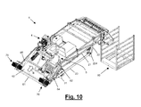
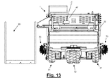
- Figures 10 , 11 and 13 show the vehicle 1 of Figure 1 in the caging configuration in the raised position on the right side.
- the surface of the gathering conveyor belt 61 is "rough", that is, it is provided with raised inserts or studs.
- the surface of the accumulating conveyor belt 62 is less profiled.
- the unloading conveyor belt 63 runs horizontally and it is not necessary for the belt surface to be rough. Its surface can also be smooth.
- the conveyor belts are made of PVC or a similar material.
- the vehicle 1 is brought inside the farm shed and made to move in direction MV ( Figure 1 ) with the pick-up conveyor belt 61 close to the ground.
- MV Figure 1
- both the pick-up conveyor belt 61 and the accumulating belt 62 are running, carrying fowl in the direction of arrows A and B, respectively.
- the speed of the pick-up conveyor belt 61 may be greater than the speed of the accumulating conveyor belt 62, as repeatedly mentioned above. In this way, the fowl collected from the ground are assembled close to each other on the accumulating belt 62, essentially occupying the entire belt.
- the operator When the operator, who is placed in the seat 52 and has complete visibility, decides that the vehicle 1 has loaded a sufficient number of fowl, the operator raises the gathering conveyor belt and stops the movement of the accumulating conveyor belt to prevent the fowl from piling up.
- the end of the gathering phase may be determined by reaching a preset weight of fowl, based on the data produced by the load cells and software program.
- the operator drives towards the place of unloading, where the cages are usually located.
- the belts 61, 62 remain preferably still also during the transfer phase.
- the operator brings the unloading conveyor belt 63 close to the cage and, when the position is right, opens the barrier 8 and starts, preferably essentially at the same time, the accumulating conveyor belt 62 and the unloading conveyor belt 63.
- the fowl are carried in the direction of arrow B and then in the transverse direction of arrow C (to the right and/or to the left).
- the sliding rear board is made to slide so that the fowl are prevented from falling off the extended unloading conveyor belt.
- the conveyor belt system is rotated upwards.
- the operator who is closely following the unloading operations, checks the weight of the fowl remaining on the accumulating conveyor belt 62 (and/or on the unloading conveyor belt) and decides when to stop filling a cage. Stopping the conveyor belts can of course be done automatically (for example based on bird weight data) or manually.
- a very advantageous feature of the vehicle relating to the present invention is that the belt-supporting structure 21 supports both the accumulating conveyor belt and the unloading conveyor belt. Therefore, raising the rear part of the structure 21 will also raise the end of the accumulating conveyor belt and the unloading conveyor belt to the level of the cages.
- the driving seat will also be raised, but, being fixed to the front part of the structure 21, it will raise relatively little above the ground. This allows the vehicle to be easily used inside farm sheds that have relatively low heights. The operator on board the vehicle shall never be in a dangerously high position during unloading operations.
- the vehicle relating to the present invention has very compact dimensions. This allows it to be used inside narrow sheds or in sheds with relatively close posts.
- the vehicle has a wheel base of about 200 cm, a gauge of about 200 cm and a total length of about 350 cm. It has also a rather light weight (about 1400 kg or however between 1000 kg and 2000 kg) which allows it to be used in multi-storey sheds, even with wooden floors.
Landscapes
- Life Sciences & Earth Sciences (AREA)
- Environmental Sciences (AREA)
- Birds (AREA)
- Animal Husbandry (AREA)
- Biodiversity & Conservation Biology (AREA)
- Housing For Livestock And Birds (AREA)
- Lighting Device Outwards From Vehicle And Optical Signal (AREA)
Applications Claiming Priority (1)
| Application Number | Priority Date | Filing Date | Title |
|---|---|---|---|
| ITMI2009A002330A IT1397221B1 (it) | 2009-12-30 | 2009-12-30 | Veicolo per raccogliere avicoli ed ingabbiarli |
Publications (1)
| Publication Number | Publication Date |
|---|---|
| EP2340708A1 true EP2340708A1 (de) | 2011-07-06 |
Family
ID=42735810
Family Applications (1)
| Application Number | Title | Priority Date | Filing Date |
|---|---|---|---|
| EP10197103A Withdrawn EP2340708A1 (de) | 2009-12-30 | 2010-12-28 | Geflügelsammeleinrichtung |
Country Status (3)
| Country | Link |
|---|---|
| EP (1) | EP2340708A1 (de) |
| CA (1) | CA2726546A1 (de) |
| IT (1) | IT1397221B1 (de) |
Families Citing this family (1)
| Publication number | Priority date | Publication date | Assignee | Title |
|---|---|---|---|---|
| CN108142318A (zh) * | 2017-09-02 | 2018-06-12 | 丁亮 | 一种可移动的网上养殖大棚 |
Citations (7)
| Publication number | Priority date | Publication date | Assignee | Title |
|---|---|---|---|---|
| DE2702174A1 (de) * | 1976-01-23 | 1977-07-28 | Giovanni Francesco Calabria | Foerdereinrichtung, insbesondere fuer lebendes gefluegel im allgemeinen |
| WO1994008451A1 (en) * | 1992-10-14 | 1994-04-28 | American Calan, Inc. | Poultry harvester |
| US5385117A (en) * | 1993-12-02 | 1995-01-31 | Hollis; Calvin L. | Poultry collection device |
| EP0713642A1 (de) | 1994-11-22 | 1996-05-29 | Anglia Autoflow Limited | Verfahren und Vorrichtung zur Bearbeitung von Tieren |
| IT1303293B1 (it) | 1998-10-30 | 2000-11-06 | Ciemme Di Calabria F Lli S N C | Apparecchiatura per il prelievo e l'introduzione in stie e simili diavicoli in genere. |
| US20020072317A1 (en) * | 2000-08-16 | 2002-06-13 | Bernard Livingston | Poultry cage staging and filling method and apparatus |
| ITMI20070331A1 (it) | 2007-02-21 | 2008-08-22 | Ciemmecalabria S R L | Veicolo raccogli-polli |
-
2009
- 2009-12-30 IT ITMI2009A002330A patent/IT1397221B1/it active
-
2010
- 2010-12-28 EP EP10197103A patent/EP2340708A1/de not_active Withdrawn
- 2010-12-29 CA CA 2726546 patent/CA2726546A1/en not_active Abandoned
Patent Citations (7)
| Publication number | Priority date | Publication date | Assignee | Title |
|---|---|---|---|---|
| DE2702174A1 (de) * | 1976-01-23 | 1977-07-28 | Giovanni Francesco Calabria | Foerdereinrichtung, insbesondere fuer lebendes gefluegel im allgemeinen |
| WO1994008451A1 (en) * | 1992-10-14 | 1994-04-28 | American Calan, Inc. | Poultry harvester |
| US5385117A (en) * | 1993-12-02 | 1995-01-31 | Hollis; Calvin L. | Poultry collection device |
| EP0713642A1 (de) | 1994-11-22 | 1996-05-29 | Anglia Autoflow Limited | Verfahren und Vorrichtung zur Bearbeitung von Tieren |
| IT1303293B1 (it) | 1998-10-30 | 2000-11-06 | Ciemme Di Calabria F Lli S N C | Apparecchiatura per il prelievo e l'introduzione in stie e simili diavicoli in genere. |
| US20020072317A1 (en) * | 2000-08-16 | 2002-06-13 | Bernard Livingston | Poultry cage staging and filling method and apparatus |
| ITMI20070331A1 (it) | 2007-02-21 | 2008-08-22 | Ciemmecalabria S R L | Veicolo raccogli-polli |
Also Published As
| Publication number | Publication date |
|---|---|
| IT1397221B1 (it) | 2013-01-04 |
| CA2726546A1 (en) | 2011-06-30 |
| ITMI20092330A1 (it) | 2011-06-30 |
Similar Documents
| Publication | Publication Date | Title |
|---|---|---|
| US6612918B2 (en) | Poultry cage staging and filling method and apparatus | |
| EP0779025B1 (de) | Melkmaschine zum automatischen Melken von Tieren | |
| US3420211A (en) | Turkey handling machine | |
| US5333981A (en) | Bale loading, transporting and unloading trailer | |
| EP2866547B1 (de) | Selbstausrichtende vorrichtung und verfahren zur erfassung von ballen | |
| FI109078B (fi) | Laitteisto ja menetelmä siipikarjan lastaamiseksi kontteihin | |
| US4766850A (en) | Method and apparatus for collecting and conveying objects from a surface | |
| US8302891B2 (en) | Scraping, hauling and compacting machine | |
| CA2776801C (en) | Apparatus for loading material | |
| US7281496B2 (en) | Poultry-loading machine | |
| US3631992A (en) | Apparatus for unloading a bale wagon one bale at a time | |
| US9560806B2 (en) | Control of conveyor speed in a bale gathering apparatus | |
| US4199913A (en) | Orchard fruit handling system | |
| US5353740A (en) | Hay distributing apparatus | |
| US8122854B2 (en) | Chicken-loading vehicle | |
| CA2726546A1 (en) | Vehicle for gathering fowl from the ground and carrying them to a place of unloading | |
| US4162135A (en) | Quarter bale turning apparatus | |
| EP2866546B1 (de) | Vorrichtung und verfahren zur erfassung von ballen | |
| EP2894969B1 (de) | System und verfahren zum transportieren von sand | |
| EP0560438B1 (de) | Melkmaschine zum automatischen Melken von Tieren | |
| US3921588A (en) | Method and apparatus for harvesting domestic fowl | |
| AU2014278895B2 (en) | Apparatus and methods for gathering and wrapping bales | |
| US3389690A (en) | Method of loading turkeys and the like | |
| US20260041067A1 (en) | Manure conveying device, in particular for use in barn egg production or broiler production | |
| US4455967A (en) | Animal feeding apparatus |
Legal Events
| Date | Code | Title | Description |
|---|---|---|---|
| PUAI | Public reference made under article 153(3) epc to a published international application that has entered the european phase |
Free format text: ORIGINAL CODE: 0009012 |
|
| AK | Designated contracting states |
Kind code of ref document: A1 Designated state(s): AL AT BE BG CH CY CZ DE DK EE ES FI FR GB GR HR HU IE IS IT LI LT LU LV MC MK MT NL NO PL PT RO RS SE SI SK SM TR |
|
| AX | Request for extension of the european patent |
Extension state: BA ME |
|
| 17P | Request for examination filed |
Effective date: 20111230 |
|
| 17Q | First examination report despatched |
Effective date: 20160219 |
|
| STAA | Information on the status of an ep patent application or granted ep patent |
Free format text: STATUS: EXAMINATION IS IN PROGRESS |
|
| STAA | Information on the status of an ep patent application or granted ep patent |
Free format text: STATUS: THE APPLICATION IS DEEMED TO BE WITHDRAWN |
|
| 18D | Application deemed to be withdrawn |
Effective date: 20170701 |