EP2341220A2 - Radialer Kanaldiffusor für eine Dampfturbinen-Abdampfhaube - Google Patents
Radialer Kanaldiffusor für eine Dampfturbinen-Abdampfhaube Download PDFInfo
- Publication number
- EP2341220A2 EP2341220A2 EP10195620A EP10195620A EP2341220A2 EP 2341220 A2 EP2341220 A2 EP 2341220A2 EP 10195620 A EP10195620 A EP 10195620A EP 10195620 A EP10195620 A EP 10195620A EP 2341220 A2 EP2341220 A2 EP 2341220A2
- Authority
- EP
- European Patent Office
- Prior art keywords
- exhaust
- turbine
- hood
- exhaust hood
- radial channel
- Prior art date
- Legal status (The legal status is an assumption and is not a legal conclusion. Google has not performed a legal analysis and makes no representation as to the accuracy of the status listed.)
- Withdrawn
Links
Images



Classifications
-
- F—MECHANICAL ENGINEERING; LIGHTING; HEATING; WEAPONS; BLASTING
- F01—MACHINES OR ENGINES IN GENERAL; ENGINE PLANTS IN GENERAL; STEAM ENGINES
- F01D—NON-POSITIVE DISPLACEMENT MACHINES OR ENGINES, e.g. STEAM TURBINES
- F01D25/00—Component parts, details, or accessories, not provided for in, or of interest apart from, other groups
- F01D25/30—Exhaust heads, chambers, or the like
Definitions
- the invention relates generally to steam turbines and more specifically to exhaust hoods for efficiently diffusing steam to a condenser.
- the prior art has employed, in the exhaust duct connected to the turbine, vanes, which have smoothly curved surfaces for effectively changing the axial flow of the steam from the turbine to the generally radial flow.
- vanes which have smoothly curved surfaces for effectively changing the axial flow of the steam from the turbine to the generally radial flow.
- U.S. Pat. 3,552,877 by Christ et al Further developments in prior art exhaust hoods for axial flow turbines, such as U.S. 4,013,378 by Herzog , have incorporated multiple sets of vanes for further smoothing flow.
- the exhaust hood includes a first set of guide vanes arranged in an exhaust duct connected to the turbine adjacent the last stage buckets thereof.
- vanes are curved to provide a relatively smooth transition of steam flow from an axial direction to a generally radial direction.
- a guide ring circumferentially surrounds the first set of guide vanes and a plurality of secondary vanes are circumferentially spaced around this guide ring.
- Steam, which is discharged radially from the first set of vanes to the secondary vanes, is directed by the secondary vanes to the discharge opening of the exhaust hood.
- the secondary vanes are substantially equally spaced around the guide ring and are curved at different angles to effect different angles of discharge of steam from these vanes.
- the angles of discharge are chosen so as to direct the steam toward the discharge opening of the exhaust hood in a manner achieving substantially uniform flow distribution across the exit plane of the last stage buckets and across the plane of the discharge opening.
- such vanes may be optimized for one set of flow conditions, they may operate with significantly less effectiveness at other flows.
- Diffusers for example, are commonly employed in steam turbines. Effective diffusers can improve turbine efficiency and output. Unfortunately, the complicated flow patterns existing in such turbines as well as the design problems caused by space limitations make fully effective diffusers almost impossible to design. A frequent result is flow separation that fully or partially destroys the ability of the diffuser to raise the static pressure as the steam velocity is reduced by increasing the flow area. For downward exhaust hoods used with axial steam turbines, the loss from the diffuser discharge to the exhaust hood discharge varies from top to bottom. At the top, much of the flow must be turned 180 degrees to place it over the diffuser and inner casing, then turned downward. Pressure at the top is thus higher than at the sides, which are in turn higher than at the bottom.
- FIG. 1 illustrates a perspective partial cutaway of a double flow steam turbine a portion of a steam turbine.
- the steam turbine generally designated 10, includes a rotor 12 mounting a plurality of turbine buckets 14.
- An inner turbine casing 16 is also illustrated mounting a plurality of diaphragms 18.
- a centrally disposed generally radial steam inlet 20 applies steam to each of the turbine buckets and stator blades on opposite axial sides of the turbine to drive the rotor.
- the stator vanes of the diaphragms 18 and the axially adjacent buckets 14 form the various stages of the turbine forming a flow path and it will be appreciated that the steam is exhausted from the final stage of the turbine for flow into a condenser beneath (not shown).
- an outer exhaust hood 21 which surrounds and supports the inner casing of the turbine as well as other parts such as the bearings.
- the turbine includes steam guides (not shown) for guiding the steam exhausting from the turbine into an outlet 26 for flow to one or more condensers.
- a plurality of support structures may be provided within the exhaust hood 21 to brace the exhaust hood and to assist in guiding the steam exhaust flow.
- An exemplary support structure 30 is situated to receive and direct the steam exhaust flow 35 from the steam turbine 10. The diffusion of the steam is restricted to the volume in the exhaust hood 21.
- the exhaust hood 21 includes an upper hood 22 and a lower hood 23.
- the upper and lower hoods are joined along a horizontal seating surface 33.
- An upper part of the lower hood 23 is reinforced with support members 34 providing a support frame 36. The weight borne by the support frame 36 is transferred at support ledge 27 to a foundation 40.
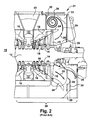
- FIG. 2 illustrates a schematic elevation view of a prior art exhaust hood for the double flow steam turbine 10 including an exhaust flow path 35.
- the steam turbine LP section consists of an inlet domain 20, turbine stages (nozzles 18 and buckets 14) and an exhaust hood 22 with diffuser 25.
- One of the main functions of the exhaust hood is to recover the static pressure and guide the exhaust steam flow 35 from last stage buckets 15 to the condenser steam outlet 26 to the condenser (not shown) underneath.
- the exhaust hood 21 includes the upper exhaust hood 22 and the lower exhaust hood 23. Flow from the last stage buckets 15, which could have very high swirl and high flow gradient in radial direction, enters the condenser through exhaust hood 21.
- an axial flow steam turbine includes an inner casing with a plurality of turbine stages providing an axial steam flow path through the inner casing and an exhaust outlet from a plurality of buckets of the last turbine stage.
- a turbine condenser is mounted below the steam turbine.
- a foundation is provided for the steam turbine.
- An exhaust hood at a downstream end of the steam turbine includes at least one exhaust path through a radial channel of a dual exhaust path from the exhaust outlet of the inner turbine casing to the turbine condenser.
- the exhaust hood is mounted to the inner turbine casing at an axial end of the inner casing. Support means are provided for the steam turbine such that the inner casing is supported directly from the foundation.
- the following embodiments of the present invention have many advantages, including improving static pressure recovery in a low pressure (LP) exhaust hood and thereby improving the heat rate or output of the steam turbine. Further, a very simple geometry construction results from the invention, thereby helping to reduce weight by eliminating a portion of the outer casing of the exhaust hood that covers the inner casing, thereby saving cost.
- LP low pressure
- a further advantage of the geometrical construction for the hood provides an opportunity to rest the inner turbine casing on the foundation for the turbine, which will lead to enhanced machine reliability.
- the present invention incorporates a concept of a radial channel, which guides the flow in upper half of the hood in the flow momentum direction. Due to this pattern of flow direction, the vortex generation in upper exhaust hood may be reduced and hence an increase in flow diffusion would result.
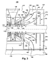
- the radial channel may be disposed behind the end wall of the exhaust diffuser to direct the flow from upper half of exhaust hood towards a turbine condenser as shown in FIG. 3 .
- This radial channel configuration will help to minimize the vortex generation in upper half of the hood. Since there is no inner casing in radial channel there will be smooth transition of flow over 180 degrees to the turbine condenser, which will improve the flow diffusion, and hence provide low pressure section efficiency improvement. Also, better diffusion of flow in upper section of the exhaust hood helps to achieve uniform pressure gradient between the last stage bucket (LSB) exits and the exhaust inlet, which has a favorable impact on LSB performance.
- LSB last stage bucket
- a first embodiment of the present invention provides an exhaust arrangement 121 for an axial flow steam turbine as illustrated in FIG. 3 .
- An inner turbine casing 116 includes one or more turbine stages of nozzles 114 and buckets 118 providing an axial steam flow path through the inner turbine casing 116.
- An exhaust outlet flows from multiple last stage buckets 115.
- An exhaust hood 125 is coupled to a downstream axial end 127 of the inner turbine casing 116.
- a turbine condenser 140 is mounted below the exhaust hood 125 for condensing and subcooling the exhausted steam.
- an exhaust hood 125 is coupled at each downstream axial end 127 of the inner casing 116 with one or more turbine condensers 140 accepting the exhausted steam.
- the exhaust hood 125 provides a dual exhaust path from the last stage buckets 118 to the turbine condenser 140.
- the exhaust hood 125 may include an upper exhaust hood 122 and a lower exhaust hood 123 separated conventionally along a horizontal joint 135 ( FIG. 4 ).
- the exhaust hood 125 includes a diffuser 150, a lower section 155, an upper section 160, and a downstream radial channel 170.
- a first exhaust path 180 for steam discharging into the exhaust hood 125 from the last stage buckets 118 includes a lower section 151 of the diffuser 150, the lower section 155 of the exhaust hood 125 and a downward discharge into the condenser 140.
- the second exhaust path 190 flowing from the last stage buckets 118 of the inner casing 116 includes an upper section 152 of the diffuser 150, the upper section 160 of the exhaust hood 125, and a downstream radial channel 170 of the exhaust hood 125 discharging downward to the turbine condenser 140 below.
- the diffuser 150 is formed between an inner wall 154 of a bearing cone 155 and steam guides 156, 157.
- the axial downstream ends of the bearing cones engage with a divider wall separating the upper section of the exhaust hood from the downstream section.
- the lower half 151 of the diffuser 150 opens into the lower section 155 of the exhaust hood 125.
- the lower section 155 of the exhaust hood opens downwardly into the turbine condenser 140.
- the upper half 152 of the diffuser 150 opens into the upper section 160 of the exhaust hood 125.
- An opening 161 for steam flow from the axial downstream end 161 of the upper section 160 of the exhaust hood 125 to the downstream radial channel 170 is provided between the upper exhaust hood casing wall 125 and the outer end 166 of the circumferential divider wall 165.
- the radial channel 170 connects the upper section 160 of the exhaust hood with the turbine condenser 140 below.
- the radial channel 170 includes an upper space 171 between a plane of the divider wall 165 and an endwall 172.
- the upper space 171 may be formed as a semi-annulus above the rotor shaft 112.
- the radial channel 170 may also include two descending exhaust spaces 173 to the turbine condenser 140.
- the descending exhaust spaces 173 may be positioned axially downstream from the divider wall 165 and be open radially to the upper section 171 of the radial channel above and to the turbine condenser 140 below.
- the two descending exhaust spaces 173 together may be formed around the rotor shaft 112, which extends axially through the exhaust arrangement 121 and divider wall 165.
- the exhaust spaces 173 may lie axially between the divider wall 165 and end wall 174.
- the two descending exhaust spaces 173 may be generally aligned in parallel for the vertical descent to the turbine condenser 140.
- the two descending exhaust spaces 173 may be an integral part of the exhaust arrangement 121 or may be enclosed in external ductwork.
- Each of the descending exhaust spaces 173 may include an inner sidewall 175 ( FIG. 6 ), wherein an opening space 176 is provided there-between.
- the opening space 176 between the descending exhaust spaces 173 of the radial channel 170 may be sufficiently large to allow personnel access to the bearing cone 145 areas.
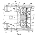
- FIG. 4 provides a top view of the steam turbine 100 with the upper exhaust hood removed. Spaces 177 and 178 are available to mount the turbine inner casing 116 to the foundation directly. At least one support arm 185 from each lateral side 186 of the turbine inner casing 116 may extend to the pads 187 on foundation wall 80.
- the exhaust hood 125 may include a reinforced section 135 which also seated on the foundation wall 80 to provide support for the exhaust hood.
- a general flow pattern 200 of exhaust along the second exhaust path is illustrated between the upper steam guide 157 and the inner wall 144 of the bearing cone 145, continuing over the inner wall 144, and around and over the divider wall 165.
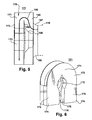
- the radial channel may be formed with different shape and contouring of outer casing as shown in FIGs. 5-6 .
- the configuration of the radial channel is modified.
- the two descending exhaust spaces of the radial channel in fluid communication with the upper section of the radial channel and with the turbine condenser may include an exhaust space on each lateral side of the exhaust hood.
- the descending exhaust space on each respective lateral side may extend radially outboard relative to the exhaust hood in a path to the turbine condenser below.
- the descending exhaust space may further curve upstream axially such that it descends vertically alongside the outer radial casing of the exhaust hood in a vertical path to the turbine condenser below.
- the vertically descending exhaust space may be enclosed in a separately enclosed volume that exhausts downward to the turbine condenser in a parallel path relative to the condenser flow from the lower section of the exhaust hood.
- FIG. 5 illustrates a three-dimensional side view of the exhaust arrangement structure 121 with the external casing of the exhaust hood removed.
- Steam exhausted from turbine inner casing 116 flows in the second exhaust path 190 between upper steam guide 157 and bearing cone 145 into upper exhaust section of exhaust hood 125.
- Flow continues over divider wall 165 into the upper section 171 of radial channel 170 between divider wall 165 and end wall 172.
- Flow continues downward through exhaust section 173 of radial channel 170 on way to condenser (not shown) below.
- FIG. 6 illustrates a three-dimensional end view of the exhaust arrangement structure 121 with a radial channel.
- the radial channel 170 includes an upper section 171 into which exhaust steam flow passing over divider wall 165 ( FIGs. 3 , 4 , 5 ) enters. Due to endwall 172, the exhaust steam flow is forced downward into two descending exhaust spaces 173 on the way to the condenser below ( FIG. 3 ).
- the two descending exhaust spaces include an inner radial surface (wall) 175.
- the two descending exhaust spaces 173 fold around rotor shaft 112 ( FIGs. 3 , 4 ) and may allow a space 176 below the rotor shaft for personnel access to the bearing cone area.
- FIG. 7 illustrates an isometric three-dimensional sectional view of the exhaust arrangement structure 121 viewed from the turbine inner casing end. Exhaust flow paths are shown as dashed lines within the individual volumes.
- the first exhaust flow path 180 flows from the diffuser volume between the lower steam guide (not shown) and the bearing cone (not shown) to the lower exhaust volume.
- the second exhaust path 190 flows from the diffuser volume between the upper steam guide (not shown) and the bearing cone (not shown) into the upper hood section 160, then into the upper section 171 of the radial channel 170 and then into the descending exhaust section 173 (one shown) on the path to the turbine condenser below (not shown).
- FIG. 8 provides a cutaway side view of the second exhaust path in the second embodiment of the exhaust arrangement 205.
- the second exhaust path from the upper half of inner casing outlet 216 flows between the steam guides 257 and an inner wall of the bearing cone 245 into the upper section of the second embodiment of exhaust hood 205.
- the divider wall 265 extends in a radial direction from the bearing cone 245.
- the second exhaust flow path 290 passes axially from the upper section 260 of the exhaust hood 205 to the radial channel 270 in the space between the divider wall 265 and the outer casing 225 of the exhaust hood.
- the second exhaust flow path 210 is forced to turn downward in the upper section 271 of the radial channel 270 by the endwall.
- a curved descending exhaust space 273 further directs the flow downward, upstream axially, and outboard relative to the exhaust hood outer casing.
- the second exhaust flow path 290 continues downward to the condenser in a flow parallel to the first exhaust path 280 from the lower section 255 of the exhaust hood.
- FIG. 9 illustrates an isometric view of one lateral side of the exhaust arrangement viewed from the turbine inner casing end.
- a first exhaust flowpath 280 from the lower half space of inner casing outlet flows between the steam guide 256 and an inner wall of the bearing cone (not shown) into the lower section of the exhaust hood and then downward to the turbine condenser.
- the second exhaust path 290 from the upper half of inner casing outlet 250 flows between the steam guide 257 and an inner wall of the bearing cone (not shown) into the upper section 260 of the exhaust hood.
- the second exhaust path 290 from the upper section 160 of the exhaust hood passes over the divider wall 265 into the radial channel 270 of the exhaust hood.
- the rear wall 272 of the downstream section forces the flow in a downward direction, passing into the curved descending exhaust space 273 which directs the flow outboard radially and upstream axially to a space 295 outboard of and parallel to the exhaust path from the lower section of the exhaust hood.
- the downward path may be in a same space or a space walled-off.
Landscapes
- Engineering & Computer Science (AREA)
- Mechanical Engineering (AREA)
- General Engineering & Computer Science (AREA)
- Turbine Rotor Nozzle Sealing (AREA)
Applications Claiming Priority (1)
| Application Number | Priority Date | Filing Date | Title |
|---|---|---|---|
| US12/648,721 US8317467B2 (en) | 2009-12-29 | 2009-12-29 | Radial channel diffuser for steam turbine exhaust hood |
Publications (1)
| Publication Number | Publication Date |
|---|---|
| EP2341220A2 true EP2341220A2 (de) | 2011-07-06 |
Family
ID=43617034
Family Applications (1)
| Application Number | Title | Priority Date | Filing Date |
|---|---|---|---|
| EP10195620A Withdrawn EP2341220A2 (de) | 2009-12-29 | 2010-12-17 | Radialer Kanaldiffusor für eine Dampfturbinen-Abdampfhaube |
Country Status (4)
| Country | Link |
|---|---|
| US (1) | US8317467B2 (de) |
| EP (1) | EP2341220A2 (de) |
| JP (1) | JP2011137460A (de) |
| RU (1) | RU2553837C2 (de) |
Cited By (1)
| Publication number | Priority date | Publication date | Assignee | Title |
|---|---|---|---|---|
| EP3054086A1 (de) * | 2015-02-05 | 2016-08-10 | Alstom Technology Ltd | Dampfturbinendiffusorkonfiguration |
Families Citing this family (11)
| Publication number | Priority date | Publication date | Assignee | Title |
|---|---|---|---|---|
| US8398359B2 (en) * | 2010-02-17 | 2013-03-19 | General Electric Company | Exhaust diffuser |
| US20130019600A1 (en) * | 2011-07-18 | 2013-01-24 | General Electric Company | Turbine exhaust arrangement |
| US9057287B2 (en) | 2011-08-30 | 2015-06-16 | General Electric Company | Butterfly plate for a steam turbine exhaust hood |
| US9062568B2 (en) | 2011-10-14 | 2015-06-23 | General Electric Company | Asymmetric butterfly plate for steam turbine exhaust hood |
| US20140026999A1 (en) * | 2012-07-25 | 2014-01-30 | Solar Turbines Incorporated | Exhaust diffuser for a gas turbine engine having curved and offset struts |
| CN106401669A (zh) * | 2015-07-31 | 2017-02-15 | 新乡航空工业(集团)有限公司 | 一种中间级涡轮出口流道结构 |
| JP6632510B2 (ja) * | 2016-10-31 | 2020-01-22 | 三菱重工業株式会社 | 蒸気タービンの排気室、蒸気タービン排気室用のフローガイド、及び、蒸気タービン |
| GB201712182D0 (en) * | 2017-07-28 | 2017-09-13 | Cummins Ltd | Diffuser space for a turbine of a turbomachine |
| US11143058B2 (en) * | 2017-12-20 | 2021-10-12 | General Electric Company | Exhaust device and an associated method thereof |
| JP6944871B2 (ja) * | 2017-12-28 | 2021-10-06 | 三菱パワー株式会社 | 排気室及び蒸気タービン |
| JP7184638B2 (ja) | 2018-12-28 | 2022-12-06 | 三菱重工業株式会社 | 蒸気タービン、及びその排気室 |
Citations (2)
| Publication number | Priority date | Publication date | Assignee | Title |
|---|---|---|---|---|
| US3552877A (en) | 1968-02-15 | 1971-01-05 | Escher Wyss Ltd | Outlet housing for an axial-flow turbomachine |
| US4013378A (en) | 1976-03-26 | 1977-03-22 | General Electric Company | Axial flow turbine exhaust hood |
Family Cites Families (13)
| Publication number | Priority date | Publication date | Assignee | Title |
|---|---|---|---|---|
| US3338052A (en) * | 1965-10-22 | 1967-08-29 | Westinghouse Electric Corp | High recovery condenser |
| SU688658A1 (ru) * | 1976-06-23 | 1979-09-30 | Предприятие П/Я А-3513 | Выхлопной патрубок турбомашины |
| JPS5566605A (en) * | 1978-11-14 | 1980-05-20 | Toshiba Corp | Exhaust casing for steam turbine |
| SU1109529A1 (ru) * | 1982-10-06 | 1984-08-23 | Производственное объединение "Турбомоторный завод" | Выхлопной патрубок теплофикационной турбины |
| JPS60183204U (ja) * | 1984-05-16 | 1985-12-05 | 株式会社東芝 | 蒸気タ−ビン |
| US5257906A (en) * | 1992-06-30 | 1993-11-02 | Westinghouse Electric Corp. | Exhaust system for a turbomachine |
| US5518366A (en) * | 1994-06-13 | 1996-05-21 | Westinghouse Electric Corporation | Exhaust system for a turbomachine |
| JP3746614B2 (ja) * | 1998-07-28 | 2006-02-15 | 三菱重工業株式会社 | 低圧蒸気タービン排気室 |
| US6484503B1 (en) * | 2000-01-12 | 2002-11-26 | Arie Raz | Compression and condensation of turbine exhaust steam |
| US6419448B1 (en) * | 2000-03-20 | 2002-07-16 | Jerzy A. Owczarek | Flow by-pass system for use in steam turbine exhaust hoods |
| JP4541950B2 (ja) | 2005-03-31 | 2010-09-08 | 株式会社日立製作所 | タービン排気装置及びその改造方法 |
| EP1921278A1 (de) * | 2006-11-13 | 2008-05-14 | ALSTOM Technology Ltd | Diffusor-und Abdampfsystem für Turbine |
| US8127557B2 (en) * | 2008-04-07 | 2012-03-06 | General Electric Company | Control systems and method for controlling a load point of a gas turbine engine |
-
2009
- 2009-12-29 US US12/648,721 patent/US8317467B2/en not_active Expired - Fee Related
-
2010
- 2010-12-17 EP EP10195620A patent/EP2341220A2/de not_active Withdrawn
- 2010-12-22 JP JP2010285230A patent/JP2011137460A/ja active Pending
- 2010-12-28 RU RU2010153499/06A patent/RU2553837C2/ru not_active IP Right Cessation
Patent Citations (2)
| Publication number | Priority date | Publication date | Assignee | Title |
|---|---|---|---|---|
| US3552877A (en) | 1968-02-15 | 1971-01-05 | Escher Wyss Ltd | Outlet housing for an axial-flow turbomachine |
| US4013378A (en) | 1976-03-26 | 1977-03-22 | General Electric Company | Axial flow turbine exhaust hood |
Cited By (1)
| Publication number | Priority date | Publication date | Assignee | Title |
|---|---|---|---|---|
| EP3054086A1 (de) * | 2015-02-05 | 2016-08-10 | Alstom Technology Ltd | Dampfturbinendiffusorkonfiguration |
Also Published As
| Publication number | Publication date |
|---|---|
| RU2010153499A (ru) | 2012-07-10 |
| RU2553837C2 (ru) | 2015-06-20 |
| US20110158799A1 (en) | 2011-06-30 |
| US8317467B2 (en) | 2012-11-27 |
| JP2011137460A (ja) | 2011-07-14 |
Similar Documents
| Publication | Publication Date | Title |
|---|---|---|
| US8317467B2 (en) | Radial channel diffuser for steam turbine exhaust hood | |
| JP3416210B2 (ja) | ターボ装置用の多区域ディフューザ | |
| JP2820403B2 (ja) | 軸流タービン | |
| JP5550318B2 (ja) | 多段気水分離装置、および気水分離器 | |
| US6419448B1 (en) | Flow by-pass system for use in steam turbine exhaust hoods | |
| JPH0842306A (ja) | ターボ機械のためのディフューザ | |
| JP5606473B2 (ja) | 蒸気タービン | |
| US3149470A (en) | Low pressure turbine exhaust hood | |
| EP2378077A2 (de) | Ummantelungswirbelentferner | |
| JP2004170064A (ja) | 境界層ブローイングを備えた燃焼器入口ディフューザ | |
| CN101255802A (zh) | 蒸汽涡轮机 | |
| US20120171030A1 (en) | Discharge scroll and turbomachine | |
| EP2385219A2 (de) | Diffusor einer Gasturbine zwischen Verdichteraustritt und Brennkammereintritt | |
| JP2008240725A5 (de) | ||
| CN104179689A (zh) | 抽出型立轴泵 | |
| JP2013525669A (ja) | ガスタービンの排ガスディフューザ | |
| EP2264286A2 (de) | Doppelströmungs-Niederdruckdampfturbinenkonfiguration | |
| EP1772595A2 (de) | Dampfturbinenauslassdiffusor | |
| JPH08260904A (ja) | 蒸気タービン排気室 | |
| US20090257868A1 (en) | Diffuser | |
| KR102056695B1 (ko) | 고효율 대용량 프란시스 수차 | |
| US8161749B2 (en) | Cooled exhaust hood plates for reduced exhaust loss | |
| KR101902240B1 (ko) | 가변형 가이드 베인을 포함하는 배기 디퓨저 및 이를 포함하는 가스터빈 | |
| JP5584281B2 (ja) | 多相流体流を相分離する装置、このような装置を備える蒸気タービン設備、およびこれに対応する運転方法 | |
| JP5693112B2 (ja) | 軸流タービン及び軸流タービンから流れを排出するための方法 |
Legal Events
| Date | Code | Title | Description |
|---|---|---|---|
| PUAI | Public reference made under article 153(3) epc to a published international application that has entered the european phase |
Free format text: ORIGINAL CODE: 0009012 |
|
| AK | Designated contracting states |
Kind code of ref document: A2 Designated state(s): AL AT BE BG CH CY CZ DE DK EE ES FI FR GB GR HR HU IE IS IT LI LT LU LV MC MK MT NL NO PL PT RO RS SE SI SK SM TR |
|
| AX | Request for extension of the european patent |
Extension state: BA ME |
|
| STAA | Information on the status of an ep patent application or granted ep patent |
Free format text: STATUS: THE APPLICATION IS DEEMED TO BE WITHDRAWN |
|
| 18D | Application deemed to be withdrawn |
Effective date: 20160701 |