EP2341242A2 - Explorateur de ressources atmosphériques pour exploiter l'énergie éolienne - Google Patents
Explorateur de ressources atmosphériques pour exploiter l'énergie éolienne Download PDFInfo
- Publication number
- EP2341242A2 EP2341242A2 EP10398010A EP10398010A EP2341242A2 EP 2341242 A2 EP2341242 A2 EP 2341242A2 EP 10398010 A EP10398010 A EP 10398010A EP 10398010 A EP10398010 A EP 10398010A EP 2341242 A2 EP2341242 A2 EP 2341242A2
- Authority
- EP
- European Patent Office
- Prior art keywords
- group
- cable
- airborne
- wind
- aerodynamic
- Prior art date
- Legal status (The legal status is an assumption and is not a legal conclusion. Google has not performed a legal analysis and makes no representation as to the accuracy of the status listed.)
- Granted
Links
Images


Classifications
-
- F—MECHANICAL ENGINEERING; LIGHTING; HEATING; WEAPONS; BLASTING
- F03—MACHINES OR ENGINES FOR LIQUIDS; WIND, SPRING, OR WEIGHT MOTORS; PRODUCING MECHANICAL POWER OR A REACTIVE PROPULSIVE THRUST, NOT OTHERWISE PROVIDED FOR
- F03D—WIND MOTORS
- F03D5/00—Other wind motors
-
- F—MECHANICAL ENGINEERING; LIGHTING; HEATING; WEAPONS; BLASTING
- F03—MACHINES OR ENGINES FOR LIQUIDS; WIND, SPRING, OR WEIGHT MOTORS; PRODUCING MECHANICAL POWER OR A REACTIVE PROPULSIVE THRUST, NOT OTHERWISE PROVIDED FOR
- F03D—WIND MOTORS
- F03D13/00—Assembly, mounting or commissioning of wind motors; Arrangements specially adapted for transporting wind motor components
- F03D13/20—Arrangements for mounting or supporting wind motors; Masts or towers for wind motors
-
- F—MECHANICAL ENGINEERING; LIGHTING; HEATING; WEAPONS; BLASTING
- F03—MACHINES OR ENGINES FOR LIQUIDS; WIND, SPRING, OR WEIGHT MOTORS; PRODUCING MECHANICAL POWER OR A REACTIVE PROPULSIVE THRUST, NOT OTHERWISE PROVIDED FOR
- F03D—WIND MOTORS
- F03D15/00—Transmission of mechanical power
- F03D15/10—Transmission of mechanical power using gearing not limited to rotary motion, e.g. with oscillating or reciprocating members
-
- F—MECHANICAL ENGINEERING; LIGHTING; HEATING; WEAPONS; BLASTING
- F03—MACHINES OR ENGINES FOR LIQUIDS; WIND, SPRING, OR WEIGHT MOTORS; PRODUCING MECHANICAL POWER OR A REACTIVE PROPULSIVE THRUST, NOT OTHERWISE PROVIDED FOR
- F03D—WIND MOTORS
- F03D80/00—Details, components or accessories not provided for in groups F03D1/00 - F03D17/00
- F03D80/10—Arrangements for warning air traffic
-
- F—MECHANICAL ENGINEERING; LIGHTING; HEATING; WEAPONS; BLASTING
- F03—MACHINES OR ENGINES FOR LIQUIDS; WIND, SPRING, OR WEIGHT MOTORS; PRODUCING MECHANICAL POWER OR A REACTIVE PROPULSIVE THRUST, NOT OTHERWISE PROVIDED FOR
- F03D—WIND MOTORS
- F03D80/00—Details, components or accessories not provided for in groups F03D1/00 - F03D17/00
- F03D80/30—Lightning protection
-
- F—MECHANICAL ENGINEERING; LIGHTING; HEATING; WEAPONS; BLASTING
- F03—MACHINES OR ENGINES FOR LIQUIDS; WIND, SPRING, OR WEIGHT MOTORS; PRODUCING MECHANICAL POWER OR A REACTIVE PROPULSIVE THRUST, NOT OTHERWISE PROVIDED FOR
- F03D—WIND MOTORS
- F03D9/00—Adaptations of wind motors for special use; Combinations of wind motors with apparatus driven thereby; Wind motors specially adapted for installation in particular locations
- F03D9/10—Combinations of wind motors with apparatus storing energy
- F03D9/19—Combinations of wind motors with apparatus storing energy storing chemical energy, e.g. using electrolysis
-
- F—MECHANICAL ENGINEERING; LIGHTING; HEATING; WEAPONS; BLASTING
- F05—INDEXING SCHEMES RELATING TO ENGINES OR PUMPS IN VARIOUS SUBCLASSES OF CLASSES F01-F04
- F05B—INDEXING SCHEME RELATING TO WIND, SPRING, WEIGHT, INERTIA OR LIKE MOTORS, TO MACHINES OR ENGINES FOR LIQUIDS COVERED BY SUBCLASSES F03B, F03D AND F03G
- F05B2240/00—Components
- F05B2240/20—Rotors
- F05B2240/201—Rotors using the Magnus-effect
-
- F—MECHANICAL ENGINEERING; LIGHTING; HEATING; WEAPONS; BLASTING
- F05—INDEXING SCHEMES RELATING TO ENGINES OR PUMPS IN VARIOUS SUBCLASSES OF CLASSES F01-F04
- F05B—INDEXING SCHEME RELATING TO WIND, SPRING, WEIGHT, INERTIA OR LIKE MOTORS, TO MACHINES OR ENGINES FOR LIQUIDS COVERED BY SUBCLASSES F03B, F03D AND F03G
- F05B2240/00—Components
- F05B2240/90—Mounting on supporting structures or systems
- F05B2240/91—Mounting on supporting structures or systems on a stationary structure
- F05B2240/917—Mounting on supporting structures or systems on a stationary structure attached to cables
-
- F—MECHANICAL ENGINEERING; LIGHTING; HEATING; WEAPONS; BLASTING
- F05—INDEXING SCHEMES RELATING TO ENGINES OR PUMPS IN VARIOUS SUBCLASSES OF CLASSES F01-F04
- F05B—INDEXING SCHEME RELATING TO WIND, SPRING, WEIGHT, INERTIA OR LIKE MOTORS, TO MACHINES OR ENGINES FOR LIQUIDS COVERED BY SUBCLASSES F03B, F03D AND F03G
- F05B2240/00—Components
- F05B2240/90—Mounting on supporting structures or systems
- F05B2240/92—Mounting on supporting structures or systems on an airbourne structure
- F05B2240/921—Mounting on supporting structures or systems on an airbourne structure kept aloft due to aerodynamic effects
-
- F—MECHANICAL ENGINEERING; LIGHTING; HEATING; WEAPONS; BLASTING
- F05—INDEXING SCHEMES RELATING TO ENGINES OR PUMPS IN VARIOUS SUBCLASSES OF CLASSES F01-F04
- F05B—INDEXING SCHEME RELATING TO WIND, SPRING, WEIGHT, INERTIA OR LIKE MOTORS, TO MACHINES OR ENGINES FOR LIQUIDS COVERED BY SUBCLASSES F03B, F03D AND F03G
- F05B2240/00—Components
- F05B2240/90—Mounting on supporting structures or systems
- F05B2240/92—Mounting on supporting structures or systems on an airbourne structure
- F05B2240/922—Mounting on supporting structures or systems on an airbourne structure kept aloft due to buoyancy effects
-
- F—MECHANICAL ENGINEERING; LIGHTING; HEATING; WEAPONS; BLASTING
- F05—INDEXING SCHEMES RELATING TO ENGINES OR PUMPS IN VARIOUS SUBCLASSES OF CLASSES F01-F04
- F05B—INDEXING SCHEME RELATING TO WIND, SPRING, WEIGHT, INERTIA OR LIKE MOTORS, TO MACHINES OR ENGINES FOR LIQUIDS COVERED BY SUBCLASSES F03B, F03D AND F03G
- F05B2240/00—Components
- F05B2240/90—Mounting on supporting structures or systems
- F05B2240/98—Mounting on supporting structures or systems which is inflatable
-
- Y—GENERAL TAGGING OF NEW TECHNOLOGICAL DEVELOPMENTS; GENERAL TAGGING OF CROSS-SECTIONAL TECHNOLOGIES SPANNING OVER SEVERAL SECTIONS OF THE IPC; TECHNICAL SUBJECTS COVERED BY FORMER USPC CROSS-REFERENCE ART COLLECTIONS [XRACs] AND DIGESTS
- Y02—TECHNOLOGIES OR APPLICATIONS FOR MITIGATION OR ADAPTATION AGAINST CLIMATE CHANGE
- Y02E—REDUCTION OF GREENHOUSE GAS [GHG] EMISSIONS, RELATED TO ENERGY GENERATION, TRANSMISSION OR DISTRIBUTION
- Y02E10/00—Energy generation through renewable energy sources
- Y02E10/70—Wind energy
- Y02E10/72—Wind turbines with rotation axis in wind direction
-
- Y—GENERAL TAGGING OF NEW TECHNOLOGICAL DEVELOPMENTS; GENERAL TAGGING OF CROSS-SECTIONAL TECHNOLOGIES SPANNING OVER SEVERAL SECTIONS OF THE IPC; TECHNICAL SUBJECTS COVERED BY FORMER USPC CROSS-REFERENCE ART COLLECTIONS [XRACs] AND DIGESTS
- Y02—TECHNOLOGIES OR APPLICATIONS FOR MITIGATION OR ADAPTATION AGAINST CLIMATE CHANGE
- Y02E—REDUCTION OF GREENHOUSE GAS [GHG] EMISSIONS, RELATED TO ENERGY GENERATION, TRANSMISSION OR DISTRIBUTION
- Y02E10/00—Energy generation through renewable energy sources
- Y02E10/70—Wind energy
- Y02E10/728—Onshore wind turbines
-
- Y—GENERAL TAGGING OF NEW TECHNOLOGICAL DEVELOPMENTS; GENERAL TAGGING OF CROSS-SECTIONAL TECHNOLOGIES SPANNING OVER SEVERAL SECTIONS OF THE IPC; TECHNICAL SUBJECTS COVERED BY FORMER USPC CROSS-REFERENCE ART COLLECTIONS [XRACs] AND DIGESTS
- Y02—TECHNOLOGIES OR APPLICATIONS FOR MITIGATION OR ADAPTATION AGAINST CLIMATE CHANGE
- Y02E—REDUCTION OF GREENHOUSE GAS [GHG] EMISSIONS, RELATED TO ENERGY GENERATION, TRANSMISSION OR DISTRIBUTION
- Y02E70/00—Other energy conversion or management systems reducing GHG emissions
- Y02E70/30—Systems combining energy storage with energy generation of non-fossil origin
Definitions
- RES Renewable Energy Sources
- the present invention developed in the field of mechanical engineering, proposes a different approach to wind energy conversion and to the harness of wind power, with a clear focus on decreasing the inherent costs of this energy source. Instead of maximizing the efficiency of currently available wind turbines, a system is conceived where the cost per unit of power output from wind power is not only much lower, but also far less dependent upon the conversion efficiency of the system, when compared with wind turbines.
- the Lois patent ( 1975 - US 3,924,827 A ) laid out the fundamentals of the concept of extracting power from medium altitude winds (100m to 400m), without the need for a rigid support connected to the ground; its concept includes pressurized lighter-than-air bodies able to convert wind energy into mechanical work which can be harnessed at a ground base.
- the 2 nd Lois patent ( 1978 - US 4,076,190 A ) is basically an improvement upon the first Lloyd patent filed (1975). It is still aimed at harnessing energy from wind speeds at medium altitude, and it still does so through a buoyant wing airfoil.
- the main improvement concerns the addition of a device capable of sensing the wind velocity gradient and elevating (or lowering) the airfoil correspondingly. It maintains the working configuration of the first patent version and adds clear remarks that the energy to be harnessed comes clearly from drag. Nevertheless all of the above mentioned problems remain unsolved.
- Loyd's Patent ( 1981 - US 4,251,040 A ) is a clear evolution from Lois initial patent, since it uses a device, on the extremity of a tether cable which is capable of harnessing energy contained in wind from both drag and lift. Hence an aerodynamic similarity with the applicant's concept exists since in this patent lift is mentioned. Other relevant features include the cable connection system to the ground station which produces electrical power. Nevertheless the similarities end here, as:
- the control is done by iteratively changing the bridle point while monitoring the power output, meaning that in practice the pitch angle of the airborne group is being blindly changed.
- Ockels patent 2000 - US 6,072,245 A is the first to integrate two fundamental concepts that have previously been introduced by Lois (1975) and Loyd (1981): possible tethered lighter-than-air forms transform wind energy into mechanical energy which can be converted, in the ground, to electrical energy (Lois, 1975) and the use of lift as the dominant form for the harnessing of the wind power. But, its operating process is entirely different than the one envisaged by the applicant:
- Carpenter's patent ( 2001 - US 6,254,034 B1 ), which draws upon his own 1996 and 1999 patents, shows no major evolution.
- the positive working phase aircraft traveling upwards and imposing tension on a cable, or downwind as Carpenter calls it
- negative working phase when the aircraft is reeled in
- Making no use of lift one can also point out that its power producing ability will always be limited.
- not being a lighter-than-air craft doubts remain over operation under wind absence conditions.
- it is a small evolution when compared to Lois (1975) initial patent, since his only significant achievement is the fact that the energy producing system (as well as the control) is simpler, yielding a more favourable cost per kWh of energy produced.
- Cornelis patent ( 2002 - NL1017171 ) seems intends to protect mainly the process for kite control through a remote controlled servo-motor that acts on a closed loop cable or ring like cable which by moving changes the bridle point position.
- An embodiment with a buoyancy component is presented and along with a description for losing the kite making it behave like a flag for the cycle for power generation.
- the only aspect related with the present invention is the bridle point changing process. It is different from the presently proposed since the bridle point is fixed and is the entire loop or ring of cable that is moving. It is applied to traction kites.
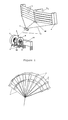
- FIG 1 a possible layout of the system is presented, where a control box (2) with actuators for the control group are shown, as well as cabling equipment (3), belonging to the cable group, which is being directed either during the unwinding or rewinding phase to the reeler (7), by a roller fairlead component (1) (such as the ones used in winches), or another cabling guiding device.
- the cabling harness not only performs the connection between different components of the airborne group but also links this group to the ground station group.
- a clutch apparatus (12) is responsible for the transmission (or its absence) of movement to the remaining elements, like the installed inertia wheel (8), the shaft (11) that feeds the alternator (10), or a propulsion system (16) or any other system able to use torque as an input.
- the mountings (9) restrain the ground station group components and support the efforts transmitted into them.
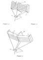
- the airborne group is also composed of inflated elements from the buoyancy system (4), a central element with a center of pressure back enough from the leading edge as to ensure natural aerodynamic stability to the airborne group when subject to an air flux and stabilizing tails (6) designed to perform similar tasks to the central element and also part of the control group.
- the inflated elements of the buoyancy system (4) also perform the task for the structural system since they are attached to, and provide support for, the aerodynamic system (5) responsible for the provision of lift. All the equipments, which might be used in order to accomplish functions other than the Atmospheric Resources Explorer main functions, are placed in the payload system (14) which, in this example, is located underneath the structural part of the airborne group.
- Figure 2 shows, another possible configuration for the airborne group of systems. Components are numbered in much the same way as they were in figure 1 , for ease of identification purposes.
- This wind power harnessing device has the ability to, in agreement with the occasional requirements, be modular. This is to increase the power output, being able to, in its final form, present dimensions as large as needed, to achieve the desired output. Enlargement is possible in all directions.
- a typical example of this modularity is shown, identifying the pattern developed and realizing that the exposed area can easily be multiplied both in height and/or span.
- Figures 3 and 4 represent the orientations of, respectively, the work and recovery phases of the airborne group of systems.
- the wing airfoils (5) present an attitude (angle of attack versus the incoming air flux) that is positive and inclined enough to generate lift along the area of the wing airfoils. This in turn transfers a traction force to the cable (3) and a subsequently feeds mechanical power to, for example, a shaft (11) in the ground station group (not present in this figure).
- a shaft (11) in the ground station group not present in this figure.
- these same profiles present an angle of attack which differs from the one used during the working phase, guaranteeing a downward movement of the airborne group, with minimized aerodynamic opposing forces, which reduces the energy required for cable rewinding. It should be noted that during this phase the supply of energy input to the airborne group is required, hence making this phase energy consuming.
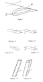
- Figure 5 demonstrates a possible cabling (3) layout able to better distribute the efforts sustained by the different components in order to prevent hazardous effects, such as cloth rupture, and also improving the normal working conditions of the system as well as its durability.
- Figure 6 exemplifies another possible arrangement for the airborne group, being a possible alternative to the drawings of figures 1, 2 , 3 and 4 .
- Figure 7 displays an example of an inflated wing profile with net buoyancy (able to stay adrift without wind). It also presents the peculiarity of having two gas tight layers, an inner layer (27) inflated with any lighter-than-air gas (hydrogen, helium, methane, neon, just to mention some possibilities) and an outer layer (28) inflated with an inert gas. This further complements the safety of the overall system since the inert gas functions as a buffer and assures that the leakage of any inflammable gas (such as hydrogen) from the inner layer (27), will never be mixed with air's oxygen in a flammable proportion.
- any inflammable gas such as hydrogen
- Figures 8, 9, 10, and 11 provide examples of components used in the aerodynamic system (5) to obtain the expected lift force.
- the component of figure 8 is a wing profile designed to provide high lift to drag ratio, as are those of figures 9 and 11 which, also have the ability to generate buoyancy.
- FIGS 12 and 13 show multiple examples (though these should not be considered restrictive) of possible buoyancy components. Its main goal is to render the whole airborne group adrift, even during periods of complete wind absence. In these particular drawings these components also serve to sustain the wing profiles which guarantee that lift is acting upon the system, thus being part of at least two systems: buoyancy (4) and structural (18).
- FIG 14 illustrates a possible embodiment of the ground station group, which is amongst other tasks, responsible for the rewinding of the cable during the recovery phase and the mechanical to electrical energy conversion that is periodically harnessed by the airborne group.
- the ground station group is, in this particular case, composed of a reeler (7) for the Cable group that feeds an alternator (10).
- an inertia wheel (8) may be added, as well as mounting supports (9) for the various components, a shaft (11) and a lock or clutch (12) in order to decouple the reeler (7) during the recovery phase.
- the flywheel (8) is one of the components of optional use, the aim being a constant energy and power transfer which is difficult to achieve without a torque smoothing device such as a flywheel.
- this device accepts energy from the airborne group during the work phase, using it to increase its rotating speed. Afterwards, when the recovery phase begins, it acts as an energy reserve, supplying power for the recovery phase of the airborne group through a reduction in its rotating velocity.
- the alternator is provided with power directly from the flywheel (8). But, in order to guarantee the supply of work during the recovery phase another device, that not a flywheel can be used, just as long as it is capable of storing energy.
- Such devices include electrochemical cells, capacitors, gas compressors, amongst other currently known devices to perform such a task.
- the alternator (10) is responsible for the conversion of mechanical movement into electrical energy.
- the mountings (9) can be used to maintain the reeler (7) and the flywheel (8) in a position in which the efforts supported by them pose no particular problem to the group, but also in a position that does not hamper any rotating movements that are required for the correct functioning of the ground station group.
- Figure 15 represents a roller fairlead system, whose objective is to minimize friction while performing the unwinding/rewinding of the cable (3) to the reeler (7).
- the roller fairlead includes a mobile part destined to drive the cable in a determinate direction and with a specific pitch, through the complete width of the reeler (7), in order to maximize the length of wound cable. Or rephrasing, in this component the cable passes through the slot between the rollers, of which one pair moves back and forth guiding the cable onto the reeler (7).
- the cable may (or not) slide over the two horizontal shafts depending on the angle of incidence at which it is arriving at this guiding system.
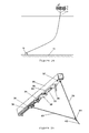
- Figure 16 proposes a solution to reduce the drag of the main cable (3) from the cable group.
- Wind form drag is minimized by placing streamlined components (29) on the cable (3), that are independent and free to rotate and align themselves naturally with the wind direction.
- These devices can also be used as wind direction sensors at different altitudes, which may be an important input to the control group.
- FIGs 17 and 18 are intended to exemplify another possible embodiment.
- the buoyancy system (4) includes several elements inflated with lighter-than-air gas, inside a large dimension balloon having enough net buoyancy for itself, the cables (3) and the airborne group.
- This embodiment solves the problem of the visual recognition elements (17), since the cables including them are not being rewound during the systems periodic movement.
- this large dimension balloon is working as a safety base in case of wind absence, for alternatives in which the airborne group might, as a whole, be heavier-than-air. In this later case, should no wind exist, the airborne group will remain stationed in this platform and will not come down any further.
- Figure 18 clearly shows the possibility for the airborne group to land on the buoyancy platform of the buoyancy system (4) which is designed to hold this component should a wind absence situation arise.
- buoyancy system balloons (4) destined to provide extra buoyancy to the Cable group are shown.
- Visual recognition elements (17) such as balloons, are also fitted in the Cable group.
- these balloons should have visual distinguishable features (e.g. contrasting colors versus the surrounding environment, sun light reflectors, light emission devices) but may also be equipped with non-visual warning devices, part of the recognition system, such as the emission of unpleasant noises in order to serve as a bird frightening device.
- Figures 20 and 21 (wherein the later is a zoom-in on the previous one) present an embodiment better suited to act as a high altitude platform which is intended to remain with the payload at a quasi-stationary position.
- the working principal is the same as explained previously. It is also a modular solution, the main difference being the presence of a propulsion system (16) to improve the positioning of the overall platform against the prevailing wind.
- the Cable group is inherently complex and multipurpose due to the need to guarantee a connection between the airborne group and the ground station group.
- the main cable connects the airborne group to the ground station group and is composed of two or more independent cables.
- the structural cable (21), one of the cables that make up this cabling system, provides for the traction effort caused by the airborne group as it is lifted during the work phase.
- Attached to this traction cable is another cable (25) which is responsible for providing information exchange between airborne and ground station groups through optical fiber cables (23), for providing lighter-than-air gas from tubing (22) to the buoyancy system and also for providing electrical power to the airborne group using conductive wires (19)..
- Both cables (21 and 25) can be bonded to each other through various tightening elements (20) placed with pre-determined spacing along the length of the cable. Since wind direction changes, if performed consistently in one direction (clockwise or counterclockwise), can impose several turns to the airborne group, this means that knots could be induce on the main cable.
- one or more cable swivels (24) may be disposed, from the control box down, along the length of the cable group. The cable swivel (24) permits that a torsion imposed on one stretch of the cablings does not have to be imposed on the next stretch of the cables, while still maintaining connection between them, and hence allowing knot formation avoidance, even when facing turbulent winds.
- Figure 23 simulates a possible configuration of units in case a thunderstorm should develop, in the area where the Atmospheric Resource Explorer is operating.
- the definition of safety level is provided with the help of an auxiliary system, featuring a lightning arrester component (26) (commonly named lightning rod), connected to the ground through a high current conductive cable (19).
- This lightning arrester is raised to a much higher altitude than the other airborne groups in the vicinity using at least a balloon filled with either helium or hot air.
- this auxiliary system meaning that all the Atmospheric Resources Explorers composing a wind farm could be considered to be at a safety level.
- Figure 24 simulates the safety procedure in the case of a possible outbreak of cyclonic winds.
- the destruction of the airborne group it might be required to go up to stratospheric altitudes, where wind conditions remain more stable.
- wind conditions remain more stable.
- Figure 25 shows one of the configurations that can be used to control the angle of attack of the aerodynamic system (5).
- the control components are mounted in a support beam (35) that can be placed in the structural system (18) of the airborne group.
- a wireless connection is established through a wireless transceiver module (34) that exchanges data with the ground station group.
- the wireless transceiver module is linked to the control board (32) through a data cable (19 and 23).
- the control board drives the electric motor (31) coupled to the linear table (30) that can change the position of the moving cable anchor (38) pulling or releasing the movable angle of attack control cable (40).
- the electric components are powered by a battery module (33).
- the fixed angle of attack control cable (39) is attached to the fixed cable anchor (37) and to the bridle point (41) that joins the control cables to the tether cable (42).
- Figure 26 shows another configuration that can be used to control the angle of attack of the aerodynamic system.
- the difference between this configuration and the one presented in figure 27 is that the moveable angle of attack control cable is pulled or released by using a cable drum coupled to an electric motor (31) instead of a linear table (30).
- the cable is redirected by a pulley (44) placed in the back end of the support beam (35).
- Figure 27 shows a cable drum (50) driven by an electric motor (31).
- the electric motor is coupled to a gear head (45), whose shaft is coupled to a toothed belt pulley (48), which transmits power to the cable drum shaft through a toothed belt (47).
- the electric motor and the gear head are attached to the structural system (18) through two plated brackets (46).
- the cable drum shaft is supported by two pillow block bearings (49).
- the above detailed invention is capable of harnessing atmospheric wind resources, through an apparatus which transforms wind's momentum into cable tension, that combined with the unwinding from a cable (3) connected to a reeler (7) at the ground station generates mechanical power which can then be converted into electrical power, as is shown in figure 1 .
- upward is defined as being oriented from the surface to the sky, going away from the user at ground station group. Upward should not be mistaken with vertical, as an upward force must only point to the sky, not straight at it. Conversely, downward is defined as being from the sky to the ground, and is not necessarily vertical or perpendicular to it.
- a module is henceforth considered to be each of a set of parts or units that can be used repeatedly to construct a more complex structure.
- the Atmospheric Resources Explorer when producing power, undertakes a periodic motion, performing a cyclic movement or working cycle.
- the control group ensures that the airborne group executes a periodical movement consisting of a work phase, in which the airborne group's attitude is that shown in figure 3 , and a recovery phase, in which the attitude of the airborne group is that presented in figure 4 , with work being required by the system to ensure the cable rewinding. For each power and recovery phase the system is said to complete a cycle or period.
- the aerodynamic system parameters will change in order to decrease the upward lift force thus allowing the main cable to be reeled in by the reeler (7), during the recovery phase.
- the airborne group is pulled downwards to return to the position from where it will start a new cycle.
- drag will always work against the system and, should upward forces still exist, either from aerodynamic lift or from net buoyancy, these will also need to be overcome.
- control group will act upon the aerodynamic (5) and structural (18) systems of the airborne group changing its aerodynamic parameters regarding the wind in order to reduce aerodynamic lift and, if possible, create enough aerodynamic downforce to cancel out any eventual positive net buoyancy. This will greatly reduce the work required to rewind the cable (3), as only drag needs to be overcome.
- a control mechanism able to extend and recover the tether cable (42) may be used to change the airborne group's attitude in regard to the incoming wind, thus changing its attack angle ( figure 27 ). Even though this may seem a preferred solution to execute the transition between the power and recovery phases it is not the sole possibility, and can be accomplished also through other forms, should they prove more efficient.
- the aerodynamic system might also include one (or more) variable configuration sub-systems, wing profiles (5) (also referred to as airfoils).
- variable configuration element can be interpreted here as:
- the aerodynamic system (5) if equipped with airfoils capable of generating lift, can be controlled in what respects to the change in attitude of the airborne group, by:
- the Airborne group's structural system (18) is composed of elements required to ensure that the deformations occurring, due to the stresses caused by all forces acting upon the airborne group (wind related, buoyancy related or cable related during the rewinding phase), will not jeopardize the system's ability to perform its main tasks.
- the elements of this system can be rigid, in order to better cope with torsion, bending and flexing moments, and better distribute stress tensions acting upon its surface, in which case they could resemble conventional beams, joints and tubular elements.
- Other elements of this system may not be so rigid and may include, stitching lines to join pieces of cloth, glue applications to bind cloth to other elements and other mounting or support points. In practice one could say that almost every element has also a function in the structural system.
- the buoyancy system (4) includes all components installed with the sole purpose of decreasing the overall airborne group's density and with the objective of producing positive net buoyancy, by which it is meant here the positive difference between the upward force created by the lighter-than-air gas volume and the weight of all components that must be airborne.
- a double layer system may be employed, as a safety measure against possible static discharges, wherein an outer layer, filed with an inert gas, completely surrounds the hydrogen inflated inner layer.
- the objective of this double layer system is to prevent the contact between the inflammable substance and the atmosphere's oxygen.
- the buoyancy system (4) should be provided with means of re-inflating the lighter-than-air components while airborne.
- One possible process to accomplish this task is to equip the main cable (3) from the cable group with a tubing system through which lighter-than-air gas will reach the airborne group.
- both the buoyancy gas and the inert gas may be obtained directly at the airborne group from equipment installed there.
- the in-situ production of the required gas during operation having the equipment (or devices) installed either in the ground station group or on the airborne group, may be accomplished according to the following schemes:
- This buoyancy system (4) may also feature elements that are not attached to the main airborne structural system (18), being attached solely to, for example, the cable group ( figure 21 ).
- the inherent advantage is that the buoyancy achieved is greater at smaller altitudes than at higher ones, since buoyancy is related to the density difference between the inner gas and the surrounding atmospheric air. Because the density of air decreases with altitude so will the above mentioned difference, thus reducing buoyancy. Having buoyancy components scattered along the main cable's length, each buoyancy component could counterweight at least its own weight and that of the cable section immediately below it.
- One added advantage of this procedure would be that an increase on the cables cross section area and consequent increase of the total cables mass may not be required. The reasoning being that each cable's section must only sustain its own weight (and not the whole structure) back to the surface.
- the airborne group due to its versatility can operate until the limits of troposphere, where the power density from wind is at its peak. In the stratosphere the wind speed diminishes (as does air density) and as a consequence there's no strong argument to operate in this region except if it is providing a permanently stable stratospheric platform, in which case advantages can be taken from such a location.
- the Cable group comprises at least the main cable (25) (having an example of a possible cross section presented in figure 24 ), which connects the ground station group to the airborne group and may have several other functions then just this structural function just mentioned and which will be further on detailed.
- the Cable group may also comprise other cables, used to perform the control of the airborne group. These other cables that connect the multiple systems of the airborne group to the control box positioned at the top end of the main cable must include the fixing points to the airborne group, which are positioned in order to ensure optimum spacing in between, thus making sure that no rupture takes place as the wind force acts upon these elements.
- the main cable example presented in figure 24 also ensures data exchange between the Airborne and ground station groups, which may be done for instance through fiber-optic cabling (23) or electric conductive wires (19). Additionally these cables (19), or similar cable, may transport electric current to power the propulsion and/or control system which, in case the Magnus effect is being used, for instance, may include engines to rotate some of the components in the aerodynamic system.
- Cable swivels (24) are used in the main cable in order to prevent a phenomenon that could otherwise occur, as the airborne group is constantly aligning with the wind and could eventual cause a constant torsion on the cable in a same direction. If no cable swivels were installed, the main cable could succumb to the resulting torsion stresses and develop knots throughout its length implying that after a period it would be almost impossible to unwind and rewind it.
- the cable does not need to be perfectly circular in its section, but it will be approximately circular, as a squared section cable would prove very difficult to unwind and rewind. Thus, the section will probably be elliptic or circular.
- the position control can be performed by changing the aerodynamic system parameters, namely the angle of attack when using airfoils and, simultaneously, pulling or releasing the tether cable (42) that connects the airborne group to the ground station group, meaning that the angle of attack can be defined by monitoring the power produced by the ground station generator.
- the angle of attack can be changed by one of the following ways:
- the angle of attack is controlled by pulling or releasing tether cables (42) from the ground station group.
- all the cables (3) are used to transmit work to the ground station.
- the data from the airborne group can be transmitted either by wireless module (34), electrical cable (19) or optic fibre (23).
- the control box controls the angle of attack by pulling or releasing the angle of attack control cables. If the control box (2) is placed in the bridle point of the airborne group, the cables may be pulled by using actuators such as for example small cable drums (50) that can pull various cables (3) or pull some cables while releasing others.
- control box may use linear tables (30) or small cable drums (50) as shown in figures 27 and 28 respectively.
- the cable drums and linear tables may in turn be actuated by electric motors (31).
- the power for the motors in the control box can be ensured by electric cables (19) from the ground station group or by any rechargeable electrical system in the airborne group.
- the data transmission can be done by electric cables (19), optic fibre (23) or a wireless communication system.
- the control box can include electric motors, cable drums, electronic components, power system, data transmission module and all non-mentioned devices that may be needed to control the orientation of to the airborne group.
- the airborne group aerodynamic stability (6) is another important factor to guarantee the airborne group's safety, preventing it from crashing onto the surface (15), with potential damaging consequences to both people and goods.
- vertical (and/or horizontal) stabilizers (6) which, due to their inherent construction, provide added aerodynamic stability as well as improving the buoyancy characteristics of the group.
- the system should be endowed with intrinsic stability characteristics with some similarities with the equilibrium of forces and moments of flying kites.
- the airborne group might include one or multiple tails that can range from simple non-structural parts, such as the ones used in kites, to more complex components.
- Atmospheric Resource Explorers might be operating in the vicinity area and their control groups should be able to communicate with each other in order to avoid collisions between neighboring airborne groups.
- Atmospheric Resource Explorers might be operating in the vicinity area and their control groups should be able to communicate with each other in order to avoid collisions between neighboring airborne groups.
- One of these methods is used as the position primary control while all other ensure redundancy to the control system.
- the control system is also responsible for the safe operation of all the apparatus, implementing safety procedures when something goes wrong in the system (e.g. a loss of wireless connection) or collision avoidance between airborne groups.
- the system's dynamic model may be estimated.
- This model can be obtained by analytical or learning techniques.
- the analytical solution requires an aerodynamic model of the airborne that is difficult to obtain due to the highly nonlinear behaviour of the system.
- the application of learning techniques requires the airborne group design to guarantee, a priori, the stability of the system, hence making it possible to launch the airborne group an initial time into the air without any modeling simulation. After this initial launch data will be acquired that, when processed, will supply important insights into the elaboration of a model.
- the electric power and data transfer by cable between the ground station group and the airborne group can be performed by a rotary transformer or slip ring in the cable drum of the ground station group. Since slip rings usually have very short time spans and imposes frictional torque forces on the system, the rotary transformer should prove the best choice. However a solution to avoid the interference of the power transfer on the data transfer might be needed and can possibly be obtained through some kind of isolation or modulation of the data signals.
- the cable may have a non-rotating end on the ground station in which case the winding has to be done using a conical system similar to the ones used to recoil fishing net cables.
- Power supply to the control system is achieved through means of a secondary power system, featuring rechargeable electrical systems such as batteries, capacitors and/or regenerative fuel cells, to name just a few.
- This secondary power system not only can be recharged from the ground, but may also be recharged, for instance, with photovoltaic generated energy, in case solar panels are mounted in the airborne group, or through wind power, should a small conventional aero-generator be attached to the structural system of the airborne group.
- the Control group if desired, can define the altitude operating interval between working and recovery phase in order to always provide the amount of power that the ground station is able to convert or the power allowed by the licensing contract.
- the force with which the cable (3) is pulled upwards, combined with the cable unwinding speed, is transformed into power. This is accomplished through the rotation of the reeler (7) and is a consequence of the force generated at the aerodynamic system (5), plus the action of net buoyancy. It is this rotating movement of the reeler that can be converted into a magnetic field variation, which will then induce an electrical current through Faraday's law. It should be noticed that the reeling system should be large enough to be able to reel in the full cable length (in order to bring the airborne group down) and, in a preferred embodiment, composed of a cable drum with a motored reeling system.
- This mechanical power can be used directly, for example connected to the propelling system of a ship, or to a pumping system or to any other system able to use mechanical energy directly.
- the ground station group can be used both in land and sea. While in land it can be:
- the absence of large compressive forces in the Atmospheric Resources Explorer herein described means that the ground station group may easily be installed on an offshore platform, which for power production may be as simple as a floating vessel anchored to the maritime sea bed or ground. If the apparatus is to be used as a High Altitude Platform, thus imposing traction forces to the ground station group, a more stable solution should be found.
- the specific advantages of installing the Atmospheric Resources Explorer in the sea one can count:
- Atmospheric Resources Explorers be used simultaneously, on a similar arrangement to a wind farm, it might be possible to dispense with some of the electrical equipment at the ground station group by putting them to work on a synchronized phase.
- This term is used whenever these apparatus perform similar cycles but have a phase decoupling which enables some of them to be performing the work phase while some others are performing the recovery phase.
- the flux of power to the system can be smoothed as the positive output of some is countered by the output requirements of some other.
- Such an operating scheme could dispense with the use of, for instance, an inertia wheel (8) as a means of providing power for the negative part of the cycle.
- a lightening strike is probably the worst scenario, as the electrical discharge can reach several hundred thousands Ampere and this could certainly endanger the Atmospheric Resource Explorer.
- an auxiliary system comprised of at least a lighter-than-air balloon (4) linked to a grounded conductor cable (19) ending on a lightening rod (26), is to be lifted into the air should a lightening storm develop.
- the Atmospheric Resource Explorer(s) operating in that area, should be brought down to an altitude inferior to that of the auxiliary system, making this auxiliary system the highest object in the vicinity sky.
- this auxiliary system is purposely built to safely drive such an electrical discharge to the surface (15), it has the highest probability of being hit by any lightening.
- each Atmospheric Resources Explorer could also include a lightning rod on its top connected to the last section of the structural cable (21) to be rewound, which could be made of a high current conductive material (such as aluminium high cross section flexible cable) that would be pressed against the grounded electric conductive roller fairlead component (1).
- a lightning rod on its top connected to the last section of the structural cable (21) to be rewound, which could be made of a high current conductive material (such as aluminium high cross section flexible cable) that would be pressed against the grounded electric conductive roller fairlead component (1).
- the airborne group will have a considerable surface area that exposed to the wind friction could accumulate a considerable static electric charge. This may be prevented if the surface material of the various airborne groups is electrically conductive, which may be ensured through the use of metalized polymer sheets, available in the market.
- an embodiment can be devised in which both the airborne and cable groups are even less electric conductive than the atmosphere and so are the most improbable path for any lightning.
- the third situation the occurrence of big waves is usually less felt in the open seas than near the shores, since the size of the wave is inversely related to the depth of the waters in which it is travelling. Still, should the system be required to be brought down, remaining afloat over the seas, this will not pose specific problems. Due to its low specific weight it is guaranteed to remain afloat. Remaining connected to the ground station group (which is firmly anchored to the bottom) the airborne group might be able to drift in the water but it will not break connection with the station, as the cable (3) is able to withstand the stresses imposed by the water on the deflated airborne group. As soon as the control group (which is water sealed for maritime use) acknowledges that the storm is over, the order will be given for the system to be refilled with the buoyancy gas, which will put the airborne group to fly again.
- the control group which is water sealed for maritime use
- the system is endowed with potential for use as a high altitude platform, also known as atmospheric or (if high enough) stratospheric platform.
- a high altitude platform also known as atmospheric or (if high enough) stratospheric platform.
- this platform achieves the pioneering aspect of remaining long-term airborne and stationary.
- the structural system (18) may be used as an aerial anchorage or support point, where a payload system (14) can be installed and controlled through appropriate measures from the control group.
- This payload system has an interface with the cable group and may be understood as a black box (or an empty volume) which is not fundamental to the proper functioning of the Atmospheric Resources Explorer or the interaction between its components.
- This payload system (14) allows the installation of equipment for both the military and the civilian market with applications as diverse as observation, scientific research, telecommunications and others.
- a brief summary of non-exclusive possible applications, for which the payload system is adequate, includes at least:
- the Atmospheric Resources Explorer may also be used as means of traction of a system otherwise subject to unstable loading, which then, due to the reduction of the compression forces, acquires the ability to support higher loads without the risk of buckling.
- the argument stands under the assumption that the ground station group is not used for electricity production (it is instead composed of a system that harness the traction force transmitted by the cables).
- Such a system can be as simple as a beam, a mast, a bar or a pole, or attain much higher scales such as a building, a bridge pillar or any other current application in structural engineering. Another such application is to use one of these platforms to install cargo lifters in construction works that span high in the sky.
- This energy could be transferred to the cargo without loss of mass, for example, through the use of a payload cabling arrangement.
- the launch might even benefit if executed inside a tower (or tubing) inside which a rarefied atmosphere can be found and/or a gas with a speed of sound over the surrounding atmospheric air.
- High altitude platforms may also be used as tourism attractions through the installation of panoramic sky-lifts, or a type of human environment simulation dome that might render the platform attractive to this new type of tourism.
Landscapes
- Engineering & Computer Science (AREA)
- Chemical & Material Sciences (AREA)
- Sustainable Development (AREA)
- Life Sciences & Earth Sciences (AREA)
- Sustainable Energy (AREA)
- Combustion & Propulsion (AREA)
- Mechanical Engineering (AREA)
- General Engineering & Computer Science (AREA)
- Electrochemistry (AREA)
- Power Engineering (AREA)
- Chemical Kinetics & Catalysis (AREA)
- Aviation & Aerospace Engineering (AREA)
- Wind Motors (AREA)
- Installation Of Indoor Wiring (AREA)
- Pharmaceuticals Containing Other Organic And Inorganic Compounds (AREA)
Applications Claiming Priority (3)
| Application Number | Priority Date | Filing Date | Title |
|---|---|---|---|
| PT103489A PT103489B (pt) | 2006-05-31 | 2006-05-31 | Sistema modular de aproveitamento de recursos atmosféricos |
| EP07747762A EP2021625B1 (fr) | 2006-05-31 | 2007-05-31 | Explorateur de ressources atmosphériques |
| PCT/PT2007/000022 WO2007139412A1 (fr) | 2006-05-31 | 2007-05-31 | Explorateur de ressources atmosphériques |
Related Parent Applications (2)
| Application Number | Title | Priority Date | Filing Date |
|---|---|---|---|
| EP07747762A Division EP2021625B1 (fr) | 2006-05-31 | 2007-05-31 | Explorateur de ressources atmosphériques |
| EP07747762.8 Division | 2007-05-31 |
Publications (3)
| Publication Number | Publication Date |
|---|---|
| EP2341242A2 true EP2341242A2 (fr) | 2011-07-06 |
| EP2341242A3 EP2341242A3 (fr) | 2017-04-26 |
| EP2341242B1 EP2341242B1 (fr) | 2018-08-01 |
Family
ID=38461776
Family Applications (2)
| Application Number | Title | Priority Date | Filing Date |
|---|---|---|---|
| EP07747762A Not-in-force EP2021625B1 (fr) | 2006-05-31 | 2007-05-31 | Explorateur de ressources atmosphériques |
| EP10398010.8A Not-in-force EP2341242B1 (fr) | 2006-05-31 | 2007-05-31 | Explorateur de ressources atmosphériques pour exploiter l'énergie éolienne |
Family Applications Before (1)
| Application Number | Title | Priority Date | Filing Date |
|---|---|---|---|
| EP07747762A Not-in-force EP2021625B1 (fr) | 2006-05-31 | 2007-05-31 | Explorateur de ressources atmosphériques |
Country Status (6)
| Country | Link |
|---|---|
| US (1) | US8247912B2 (fr) |
| EP (2) | EP2021625B1 (fr) |
| AT (1) | ATE508275T1 (fr) |
| DE (1) | DE602007014355D1 (fr) |
| PT (1) | PT103489B (fr) |
| WO (1) | WO2007139412A1 (fr) |
Cited By (3)
| Publication number | Priority date | Publication date | Assignee | Title |
|---|---|---|---|---|
| CN102022270B (zh) * | 2009-09-23 | 2012-09-05 | 中国中煤能源集团有限公司 | 悬浮式风能接收装置 |
| WO2016150561A1 (fr) | 2015-03-20 | 2016-09-29 | Suwis Sagl | Dispositif d'air de traction, dispositif d'air pour un parc éolien et parc éolien pour la production d'énergie électrique, navire doté d'un dispositif d'air de traction |
| IT201700023540A1 (it) * | 2017-03-06 | 2018-09-06 | Marco Ghivarello | Ala customizzata per utilizzo su generatori di tipo airborne wind energy (awe) |
Families Citing this family (79)
| Publication number | Priority date | Publication date | Assignee | Title |
|---|---|---|---|---|
| ITTO20060491A1 (it) * | 2006-07-04 | 2006-10-03 | Massimo Ippolito | Sistema eolico per la conversione di energia mediante una turbina ad asse verticale azionata per mezzo di profili alari di potenza e procedimento di produzione di energia elettrica mediante tale sistema |
| US20110049894A1 (en) * | 2006-10-06 | 2011-03-03 | Green William M | Electricity Generating Assembly |
| ITTO20070233A1 (it) * | 2007-03-30 | 2007-06-29 | Massimo Ippolito | Sistema eolico per la conversione di energia mediante la traslazione su rotaia di moduli trainati da profili alari di potenza e procedimento di produzione di energia elettrica mediante tale sistema. |
| FR2931451B1 (fr) * | 2008-05-22 | 2010-12-17 | Fmc Technologies Sa | Dispositif de commande pour systeme de chargement et/ou dechargement de fluides |
| US20110101692A1 (en) * | 2008-07-16 | 2011-05-05 | Nykolai Bilaniuk | Airborne wind powered generator |
| GB0812937D0 (en) * | 2008-07-16 | 2008-08-20 | Whitelaw Matthew | Tidal drag line |
| MX2011000722A (es) * | 2008-07-18 | 2011-08-12 | Baseload Energy Inc | Manejo de cables retenedores para generadores de energia electrica en el aire. |
| US20110210559A1 (en) * | 2008-08-08 | 2011-09-01 | Zanettistudios S.R.L. | Energy generation system with self opening and closing of sails |
| US9000605B2 (en) * | 2008-10-15 | 2015-04-07 | Altaeros Energies, Inc. | Lighter-than-air craft for energy-producing turbines |
| WO2010064918A1 (fr) * | 2008-12-03 | 2010-06-10 | Prototech As | Système de conversion d'énergie |
| US20110133023A1 (en) * | 2009-01-21 | 2011-06-09 | John Steven Surmont | Collapsible aerial payload deployment system and method |
| US20100185346A1 (en) * | 2009-01-21 | 2010-07-22 | John Steven Surmont | Aerial payload deployment method |
| US20110147513A1 (en) * | 2009-01-21 | 2011-06-23 | John Steven Surmont | Aerial payload deployment system |
| WO2010099447A1 (fr) * | 2009-02-26 | 2010-09-02 | Sky Windpower Corporation | Générateur d'énergie éolienne aéroporté amarré |
| US20100308174A1 (en) * | 2009-06-03 | 2010-12-09 | Grant Calverley | Rotocraft power-generation, control apparatus and method |
| CN102011691B (zh) * | 2009-09-04 | 2012-01-25 | 中国中煤能源集团有限公司 | 浮空式风能接收装置 |
| ITTO20090706A1 (it) * | 2009-09-16 | 2009-12-16 | Ce S I Ct Studi Ind Di Taddei Simona | Sistema di rinvio e guida antiattorcigliamento per cavi correnti. |
| DE102010008061A1 (de) * | 2010-02-16 | 2011-12-15 | Erwin Becker | Umlaufrollenwindturbine und Verfahren zur Stromerzeugung aus Windenergie |
| US8437891B2 (en) * | 2010-04-13 | 2013-05-07 | The United States Of America As Represented By The Secretary Of The Navy | Method and apparatus for parafoil guidance that accounts for ground winds |
| US8602363B2 (en) * | 2010-05-06 | 2013-12-10 | Quinn Larson | Power generating kite system |
| CN103249945A (zh) * | 2010-08-05 | 2013-08-14 | 侧风能源系统公司 | 使用系留翼面来利用风能的方法和系统 |
| US20120086210A1 (en) * | 2010-10-07 | 2012-04-12 | Dennis John Gray | Device for Extracting Energy from Moving Air or Moving Water |
| US20120181380A1 (en) * | 2011-01-19 | 2012-07-19 | Van Staagen Peter K | System for providing a rapidly elevated aerostat platform |
| US20120235410A1 (en) * | 2011-03-15 | 2012-09-20 | Serrano Richard J | Lighter than air wind and solar energy conversion system |
| PT105565A (pt) * | 2011-03-15 | 2012-09-17 | Omnidea Lda | Aeronave |
| US8446034B1 (en) * | 2011-10-13 | 2013-05-21 | Geoffrey Stevens | Electric power generation using a wind chute |
| WO2013085800A1 (fr) * | 2011-12-04 | 2013-06-13 | Leonid Goldstein | Dispositif éolien avec voile dynamique, câble aérodynamique ou mécanisme au sol amélioré |
| EP2610481B1 (fr) * | 2011-12-27 | 2017-01-25 | Minesto AB | Amarre pour véhicule mobile immergé |
| ES2605421T3 (es) * | 2012-02-27 | 2017-03-14 | Ampyx Power B.V. | Sistema y procedimiento de producción de energía eólica en vuelo |
| NL2010370C2 (en) | 2012-02-29 | 2015-02-04 | Gregory Howard Hastings | Tethered gyroglider control systems. |
| SG194257A1 (en) * | 2012-04-26 | 2013-11-29 | Yik Hei Sia | Power generating windbags and water-bags |
| CA2884734A1 (fr) | 2012-09-19 | 2014-03-27 | Solar Ship Inc. | Aeronef alimente par pile solaire regenerant de l'hydrogene |
| US10427772B2 (en) | 2012-09-19 | 2019-10-01 | Solar Ship Inc. | Hydrogen-regenerating solar-powered aircraft |
| WO2014109917A1 (fr) * | 2013-01-10 | 2014-07-17 | Leonid Goldstein | Système d'énergie éolienne aéroporté |
| BR102013001316B1 (pt) | 2013-01-18 | 2021-11-03 | Altave Industria, Comercio E Exportação De Aeronaves Ltda-me | Dispositivo de ancoragem de aeróstatos |
| ITTO20130481A1 (it) * | 2013-06-12 | 2013-09-11 | Kite Gen Res Srl | Ala a funzionamento bimodale. |
| US20150020865A1 (en) * | 2013-07-17 | 2015-01-22 | Quan Xiao | Methods and apparatus for Inflatable concentrated solar energy station/balloon and self supporting cable |
| US9777698B2 (en) | 2013-11-12 | 2017-10-03 | Daniel Keith Schlak | Multiple motor gas turbine engine system with auxiliary gas utilization |
| US9205921B1 (en) | 2013-12-19 | 2015-12-08 | Google Inc. | Methods and systems for conserving power during hover flight |
| US9317043B2 (en) * | 2013-12-19 | 2016-04-19 | Google Inc. | Path based power generation control for an aerial vehicle |
| US9475589B2 (en) * | 2013-12-20 | 2016-10-25 | Google Inc. | Systems and apparatus for winch drum mechanism |
| US9389132B1 (en) | 2013-12-26 | 2016-07-12 | Google Inc. | Methods and systems for estimating an orientation of a tethered aerial vehicle relative to wind |
| US9212032B2 (en) * | 2013-12-30 | 2015-12-15 | Google Inc. | Extruded drum surface for storage of tether |
| US9308975B2 (en) | 2013-12-30 | 2016-04-12 | Google Inc. | Spar buoy platform |
| JP6339209B2 (ja) * | 2014-02-07 | 2018-06-06 | ミネスト・アーベー | 水中発電プラント |
| US20150233254A1 (en) * | 2014-02-17 | 2015-08-20 | Edmund Daniel Villarreal | Vented airfoil assemblies |
| RU2016141581A (ru) * | 2014-03-26 | 2018-04-26 | Секвоя Отомейшн С.Р.Л. | Система зарядки энергией, связанная с остановкой электрического транспортного средства |
| US9587630B2 (en) * | 2014-03-31 | 2017-03-07 | Leonid Goldstein | Rotor kite wind energy system and more |
| US20150330366A1 (en) * | 2014-05-17 | 2015-11-19 | Young Suk WOO | Medium/Large Electricity Generator Equipped with Automatically Winding and Un-winding Kite Cable Mechanism for minimum energy loss |
| US20150330368A1 (en) * | 2014-05-18 | 2015-11-19 | Leonid Goldstein | Airborne wind energy system with rotary wing, flying generator and optional multi-leg tether |
| US9884692B2 (en) | 2014-06-30 | 2018-02-06 | X Development Llc | Systems and methods for controlling rotation and twist of a tether |
| WO2016057171A1 (fr) * | 2014-09-18 | 2016-04-14 | Vision Engineering Solutions, LLC | Systèmes de profilage atmosphérique |
| US9546954B2 (en) | 2014-09-18 | 2017-01-17 | Vision Engineering Solutions, LLC | Atmosphere profiling systems |
| US9683549B2 (en) | 2014-11-05 | 2017-06-20 | Hassan Mohajer | Turbine with dynamically adaptable savonius blades |
| GB201420109D0 (en) * | 2014-11-12 | 2014-12-24 | Kite Power Solutions Ltd | A kite |
| GB2532764A (en) * | 2014-11-27 | 2016-06-01 | Kite Power Solutions Ltd | A winch |
| US10024297B2 (en) | 2014-12-18 | 2018-07-17 | Cyrus H Gerami | Reciprocating motion energy conversion apparatus |
| US9528497B2 (en) * | 2015-01-06 | 2016-12-27 | Suey-Yueh Hu | Vehicular wind power generator |
| NL2014817B1 (en) * | 2015-05-18 | 2017-01-31 | Seacurrent Holding B V | Method and system for energy conversion from a flow of fluid. |
| PH12017550130B1 (en) * | 2015-05-18 | 2022-08-19 | Seaqurrent Holding B V | Method and system for energy conversion from a flow of fluid |
| US10118696B1 (en) | 2016-03-31 | 2018-11-06 | Steven M. Hoffberg | Steerable rotating projectile |
| DE102016106138A1 (de) * | 2016-04-04 | 2017-10-05 | Bernd Lau | Auftriebskörper zur schwebenden Anordnung über der Erdoberfläche, System zur schwebenden Anordnung eines Auftriebskörpers und Verfahren zur Bereitstellung einer Funktionseinheit |
| US10280034B2 (en) * | 2016-12-02 | 2019-05-07 | Makani Technologies Llc | Floating counter-balanced levelwind carrier system |
| US10301143B2 (en) | 2016-12-02 | 2019-05-28 | Makani Technologies Llc | Sensor equipped tether guide with open tether channel |
| DE102017205647A1 (de) * | 2017-03-14 | 2018-09-20 | Bitmanagement Software GmbH | Verfahren zum bestimmen eines pfades entlang eines objekts, system und verfahren zum automatischen inspizieren eines objekts |
| DK3592973T3 (da) * | 2017-04-18 | 2023-08-28 | Siemens Gamesa Renewable Energy As | Fremgangsmåde til montering af komponenter til en vindmølle og løftearrangement |
| DE102017206747A1 (de) * | 2017-04-21 | 2018-10-25 | Sanfritsch Gmbh | Seil zur ortsfesten Fixierung eines Höhenwindkraftwerks |
| IT201700096187A1 (it) * | 2017-08-25 | 2019-02-25 | Paolo Tili | Vela-aquilone aerostatica munita di cornice di supporto, sistema d'illuminazione e cavi distanziati |
| WO2019108686A1 (fr) * | 2017-11-28 | 2019-06-06 | Facebook, Inc. | Véhicule aérien sans pilote à deux cerfs-volants |
| US10844839B2 (en) | 2018-03-19 | 2020-11-24 | Hood Technology Corporation | Wind harvesting systems and methods |
| US11712637B1 (en) | 2018-03-23 | 2023-08-01 | Steven M. Hoffberg | Steerable disk or ball |
| US10723602B2 (en) * | 2018-10-11 | 2020-07-28 | Goodrich Corporation | Cable offset detection with contact |
| CN109441726A (zh) * | 2018-12-05 | 2019-03-08 | 贵州理工学院 | 一种电机组发散式分布的高空发电装置及方法 |
| CN113126633B (zh) * | 2019-12-30 | 2022-05-06 | 中国科学院沈阳自动化研究所 | 一种轻型长航程auv的零攻角定深航行控制方法 |
| CN113135282B (zh) * | 2020-01-19 | 2024-04-09 | 苏州泰思特电子科技有限公司 | 具有防雷电功能的飞艇 |
| DE102021106494A1 (de) * | 2021-03-17 | 2022-09-22 | Harald Kuhn | Energieerzeugungsvorrichtung |
| FR3123317B1 (fr) * | 2021-05-27 | 2023-08-25 | Wind Fisher SAS | Système de pilotage à distance d’un aéronef à effet Magnus |
| CN114436146A (zh) * | 2022-03-09 | 2022-05-06 | 上海振华重工(集团)股份有限公司 | 一种用于高空风能发电的摩擦绞车 |
| CN116127570B (zh) * | 2023-01-03 | 2024-08-30 | 中国电力工程顾问集团有限公司 | 空中伞梯系统的稳定性判别方法及装置 |
Citations (8)
| Publication number | Priority date | Publication date | Assignee | Title |
|---|---|---|---|---|
| US3924827A (en) | 1975-04-25 | 1975-12-09 | Lambros Lois | Apparatus for extracting energy from winds at significant height above the surface |
| US4076190A (en) | 1976-03-30 | 1978-02-28 | Lambros Lois | Apparatus for extracting energy from winds at significant height above the surface |
| US4251040A (en) | 1978-12-11 | 1981-02-17 | Loyd Miles L | Wind driven apparatus for power generation |
| FR2475148A1 (fr) | 1980-02-06 | 1981-08-07 | Guerin Jean | Eolienne flottante |
| US6072245A (en) | 1996-11-12 | 2000-06-06 | Ockels; Wubbo Johannes | Wind-driven driving apparatus employing kites |
| US6254034B1 (en) | 1999-09-20 | 2001-07-03 | Howard G. Carpenter | Tethered aircraft system for gathering energy from wind |
| NL1017171C1 (nl) | 2001-01-23 | 2002-07-25 | Cornelis Eerkens | Werkwijze en inrichting voor het opwekken van electriciteit met windenergie op grote hoogte. |
| US6523781B2 (en) | 2000-08-30 | 2003-02-25 | Gary Dean Ragner | Axial-mode linear wind-turbine |
Family Cites Families (10)
| Publication number | Priority date | Publication date | Assignee | Title |
|---|---|---|---|---|
| US4073516A (en) * | 1975-06-06 | 1978-02-14 | Alberto Kling | Wind driven power plant |
| US4084102A (en) * | 1976-01-19 | 1978-04-11 | Charles Max Fry | Wind driven, high altitude power apparatus |
| US4124182A (en) * | 1977-11-14 | 1978-11-07 | Arnold Loeb | Wind driven energy system |
| SE7901237L (sv) * | 1979-02-13 | 1980-08-14 | Peter Olof Broberg | Energisystem |
| US4659940A (en) * | 1982-04-27 | 1987-04-21 | Cognitronics Corporation | Power generation from high altitude winds |
| US6498402B2 (en) * | 2000-11-16 | 2002-12-24 | Manuel Munoz Saiz | Wing energy catchment device |
| GB2411209A (en) * | 2004-02-20 | 2005-08-24 | Rolls Royce Plc | Wind-driven power generating apparatus |
| US7335000B2 (en) * | 2005-05-03 | 2008-02-26 | Magenn Power, Inc. | Systems and methods for tethered wind turbines |
| US7275719B2 (en) * | 2005-11-28 | 2007-10-02 | Olson Gaylord G | Wind drive apparatus for an aerial wind power generation system |
| US20070120005A1 (en) * | 2005-11-28 | 2007-05-31 | Olson Gaylord G | Aerial wind power generation system |
-
2006
- 2006-05-31 PT PT103489A patent/PT103489B/pt active IP Right Grant
-
2007
- 2007-05-31 WO PCT/PT2007/000022 patent/WO2007139412A1/fr not_active Ceased
- 2007-05-31 US US12/302,435 patent/US8247912B2/en active Active - Reinstated
- 2007-05-31 EP EP07747762A patent/EP2021625B1/fr not_active Not-in-force
- 2007-05-31 AT AT07747762T patent/ATE508275T1/de not_active IP Right Cessation
- 2007-05-31 EP EP10398010.8A patent/EP2341242B1/fr not_active Not-in-force
- 2007-05-31 DE DE602007014355T patent/DE602007014355D1/de active Active
Patent Citations (8)
| Publication number | Priority date | Publication date | Assignee | Title |
|---|---|---|---|---|
| US3924827A (en) | 1975-04-25 | 1975-12-09 | Lambros Lois | Apparatus for extracting energy from winds at significant height above the surface |
| US4076190A (en) | 1976-03-30 | 1978-02-28 | Lambros Lois | Apparatus for extracting energy from winds at significant height above the surface |
| US4251040A (en) | 1978-12-11 | 1981-02-17 | Loyd Miles L | Wind driven apparatus for power generation |
| FR2475148A1 (fr) | 1980-02-06 | 1981-08-07 | Guerin Jean | Eolienne flottante |
| US6072245A (en) | 1996-11-12 | 2000-06-06 | Ockels; Wubbo Johannes | Wind-driven driving apparatus employing kites |
| US6254034B1 (en) | 1999-09-20 | 2001-07-03 | Howard G. Carpenter | Tethered aircraft system for gathering energy from wind |
| US6523781B2 (en) | 2000-08-30 | 2003-02-25 | Gary Dean Ragner | Axial-mode linear wind-turbine |
| NL1017171C1 (nl) | 2001-01-23 | 2002-07-25 | Cornelis Eerkens | Werkwijze en inrichting voor het opwekken van electriciteit met windenergie op grote hoogte. |
Cited By (5)
| Publication number | Priority date | Publication date | Assignee | Title |
|---|---|---|---|---|
| CN102022270B (zh) * | 2009-09-23 | 2012-09-05 | 中国中煤能源集团有限公司 | 悬浮式风能接收装置 |
| WO2016150561A1 (fr) | 2015-03-20 | 2016-09-29 | Suwis Sagl | Dispositif d'air de traction, dispositif d'air pour un parc éolien et parc éolien pour la production d'énergie électrique, navire doté d'un dispositif d'air de traction |
| CN107592848A (zh) * | 2015-03-20 | 2018-01-16 | 司盖普股份公司 | 牵引空气装置、用于风力设备的空气装置、用于电力生产的风力设备和设置有牵引空气装置的船舶 |
| US10953970B2 (en) | 2015-03-20 | 2021-03-23 | Skypull Sa | Traction air device, air device for a wind plant and wind plant for electric power production, ship provided with a traction air device |
| IT201700023540A1 (it) * | 2017-03-06 | 2018-09-06 | Marco Ghivarello | Ala customizzata per utilizzo su generatori di tipo airborne wind energy (awe) |
Also Published As
| Publication number | Publication date |
|---|---|
| DE602007014355D1 (de) | 2011-06-16 |
| EP2021625A1 (fr) | 2009-02-11 |
| EP2341242A3 (fr) | 2017-04-26 |
| US20090278353A1 (en) | 2009-11-12 |
| PT103489A (pt) | 2007-11-30 |
| ATE508275T1 (de) | 2011-05-15 |
| EP2021625B1 (fr) | 2011-05-04 |
| EP2341242B1 (fr) | 2018-08-01 |
| WO2007139412B1 (fr) | 2008-02-21 |
| US8247912B2 (en) | 2012-08-21 |
| WO2007139412A1 (fr) | 2007-12-06 |
| PT103489B (pt) | 2008-11-28 |
Similar Documents
| Publication | Publication Date | Title |
|---|---|---|
| EP2341242B1 (fr) | Explorateur de ressources atmosphériques pour exploiter l'énergie éolienne | |
| US20230407842A1 (en) | Power generating windbags and waterbags | |
| US8864064B2 (en) | Wind power generation system for lighter than air (LTA) platforms | |
| EP2712346B1 (fr) | Plate-forme aérienne | |
| US9030038B2 (en) | Tethered airborne wind power generator system | |
| CN107592848B (zh) | 牵引空气装置、用于风力设备的空气装置、用于电力生产的风力设备和设置有牵引空气装置的船舶 | |
| US20170363070A1 (en) | Methods and Systems of Maintaining an Offshore Power Plant | |
| GB2469740A (en) | Extraction of energy from the wind using kites | |
| US20170363069A1 (en) | Systems and Methods for Offshore Power Generation Using Airborne Power Generating Craft Tethered to a Floating Structure | |
| US20170363066A1 (en) | Methods and Systems for Electrical Isolation in an Offshore Power Generation Plant | |
| JP2004232461A (ja) | 発電装置 | |
| US20170363067A1 (en) | Methods and Systems for Maintaining an Offshore Power Plant Having Airborne Power Generating Craft | |
| WO2007051034A2 (fr) | Machine a energie eolienne dynamique statique | |
| US20100001534A1 (en) | Electric Power Generation System Using Hydro Turbine Tracted by Paraglider | |
| US20170363068A1 (en) | Systems and Methods for Offshore Power Generation Using Airborne Power Generating Craft | |
| JPH0321592A (ja) | 高空係留浮上装置と浮上方法 | |
| JPH02161173A (ja) | 滞空式の風力発電装置 | |
| CA2342430A1 (fr) | Transporteur robotise |
Legal Events
| Date | Code | Title | Description |
|---|---|---|---|
| PUAI | Public reference made under article 153(3) epc to a published international application that has entered the european phase |
Free format text: ORIGINAL CODE: 0009012 |
|
| AC | Divisional application: reference to earlier application |
Ref document number: 2021625 Country of ref document: EP Kind code of ref document: P |
|
| AK | Designated contracting states |
Kind code of ref document: A2 Designated state(s): AT BE BG CH CY CZ DE DK EE ES FI FR GB GR HU IE IS IT LI LT LU LV MC MT NL PL PT RO SE SI SK TR |
|
| PUAL | Search report despatched |
Free format text: ORIGINAL CODE: 0009013 |
|
| AK | Designated contracting states |
Kind code of ref document: A3 Designated state(s): AT BE BG CH CY CZ DE DK EE ES FI FR GB GR HU IE IS IT LI LT LU LV MC MT NL PL PT RO SE SI SK TR |
|
| RIC1 | Information provided on ipc code assigned before grant |
Ipc: A63H 27/08 20060101ALI20170322BHEP Ipc: F03D 5/00 20060101AFI20170322BHEP Ipc: F03D 13/20 20160101ALI20170322BHEP |
|
| STAA | Information on the status of an ep patent application or granted ep patent |
Free format text: STATUS: REQUEST FOR EXAMINATION WAS MADE |
|
| 17P | Request for examination filed |
Effective date: 20171025 |
|
| RBV | Designated contracting states (corrected) |
Designated state(s): AT BE BG CH CY CZ DE DK EE ES FI FR GB GR HU IE IS IT LI LT LU LV MC MT NL PL PT RO SE SI SK TR |
|
| GRAP | Despatch of communication of intention to grant a patent |
Free format text: ORIGINAL CODE: EPIDOSNIGR1 |
|
| STAA | Information on the status of an ep patent application or granted ep patent |
Free format text: STATUS: GRANT OF PATENT IS INTENDED |
|
| RIC1 | Information provided on ipc code assigned before grant |
Ipc: F03D 5/00 20060101AFI20180131BHEP Ipc: A63H 27/08 20060101ALI20180131BHEP Ipc: F03D 13/20 20160101ALI20180131BHEP |
|
| INTG | Intention to grant announced |
Effective date: 20180222 |
|
| GRAS | Grant fee paid |
Free format text: ORIGINAL CODE: EPIDOSNIGR3 |
|
| GRAA | (expected) grant |
Free format text: ORIGINAL CODE: 0009210 |
|
| STAA | Information on the status of an ep patent application or granted ep patent |
Free format text: STATUS: THE PATENT HAS BEEN GRANTED |
|
| AC | Divisional application: reference to earlier application |
Ref document number: 2021625 Country of ref document: EP Kind code of ref document: P |
|
| AK | Designated contracting states |
Kind code of ref document: B1 Designated state(s): AT BE BG CH CY CZ DE DK EE ES FI FR GB GR HU IE IS IT LI LT LU LV MC MT NL PL PT RO SE SI SK TR |
|
| REG | Reference to a national code |
Ref country code: GB Ref legal event code: FG4D |
|
| REG | Reference to a national code |
Ref country code: CH Ref legal event code: EP Ref country code: AT Ref legal event code: REF Ref document number: 1024608 Country of ref document: AT Kind code of ref document: T Effective date: 20180815 |
|
| REG | Reference to a national code |
Ref country code: IE Ref legal event code: FG4D |
|
| REG | Reference to a national code |
Ref country code: DE Ref legal event code: R096 Ref document number: 602007055614 Country of ref document: DE |
|
| REG | Reference to a national code |
Ref country code: NL Ref legal event code: MP Effective date: 20180801 |
|
| REG | Reference to a national code |
Ref country code: LT Ref legal event code: MG4D |
|
| REG | Reference to a national code |
Ref country code: AT Ref legal event code: MK05 Ref document number: 1024608 Country of ref document: AT Kind code of ref document: T Effective date: 20180801 |
|
| PG25 | Lapsed in a contracting state [announced via postgrant information from national office to epo] |
Ref country code: PL Free format text: LAPSE BECAUSE OF FAILURE TO SUBMIT A TRANSLATION OF THE DESCRIPTION OR TO PAY THE FEE WITHIN THE PRESCRIBED TIME-LIMIT Effective date: 20180801 Ref country code: FI Free format text: LAPSE BECAUSE OF FAILURE TO SUBMIT A TRANSLATION OF THE DESCRIPTION OR TO PAY THE FEE WITHIN THE PRESCRIBED TIME-LIMIT Effective date: 20180801 Ref country code: IS Free format text: LAPSE BECAUSE OF FAILURE TO SUBMIT A TRANSLATION OF THE DESCRIPTION OR TO PAY THE FEE WITHIN THE PRESCRIBED TIME-LIMIT Effective date: 20181201 Ref country code: LT Free format text: LAPSE BECAUSE OF FAILURE TO SUBMIT A TRANSLATION OF THE DESCRIPTION OR TO PAY THE FEE WITHIN THE PRESCRIBED TIME-LIMIT Effective date: 20180801 Ref country code: BG Free format text: LAPSE BECAUSE OF FAILURE TO SUBMIT A TRANSLATION OF THE DESCRIPTION OR TO PAY THE FEE WITHIN THE PRESCRIBED TIME-LIMIT Effective date: 20181101 Ref country code: AT Free format text: LAPSE BECAUSE OF FAILURE TO SUBMIT A TRANSLATION OF THE DESCRIPTION OR TO PAY THE FEE WITHIN THE PRESCRIBED TIME-LIMIT Effective date: 20180801 Ref country code: NL Free format text: LAPSE BECAUSE OF FAILURE TO SUBMIT A TRANSLATION OF THE DESCRIPTION OR TO PAY THE FEE WITHIN THE PRESCRIBED TIME-LIMIT Effective date: 20180801 Ref country code: GR Free format text: LAPSE BECAUSE OF FAILURE TO SUBMIT A TRANSLATION OF THE DESCRIPTION OR TO PAY THE FEE WITHIN THE PRESCRIBED TIME-LIMIT Effective date: 20181102 Ref country code: SE Free format text: LAPSE BECAUSE OF FAILURE TO SUBMIT A TRANSLATION OF THE DESCRIPTION OR TO PAY THE FEE WITHIN THE PRESCRIBED TIME-LIMIT Effective date: 20180801 |
|
| REG | Reference to a national code |
Ref country code: CH Ref legal event code: PK Free format text: BERICHTIGUNGEN |
|
| RIC2 | Information provided on ipc code assigned after grant |
Ipc: F03D 13/20 20160101ALI20180131BHEP Ipc: F03D 5/00 20060101AFI20180131BHEP Ipc: A63H 27/08 20060101ALI20180131BHEP |
|
| PG25 | Lapsed in a contracting state [announced via postgrant information from national office to epo] |
Ref country code: LV Free format text: LAPSE BECAUSE OF FAILURE TO SUBMIT A TRANSLATION OF THE DESCRIPTION OR TO PAY THE FEE WITHIN THE PRESCRIBED TIME-LIMIT Effective date: 20180801 Ref country code: ES Free format text: LAPSE BECAUSE OF FAILURE TO SUBMIT A TRANSLATION OF THE DESCRIPTION OR TO PAY THE FEE WITHIN THE PRESCRIBED TIME-LIMIT Effective date: 20180801 |
|
| PG25 | Lapsed in a contracting state [announced via postgrant information from national office to epo] |
Ref country code: CZ Free format text: LAPSE BECAUSE OF FAILURE TO SUBMIT A TRANSLATION OF THE DESCRIPTION OR TO PAY THE FEE WITHIN THE PRESCRIBED TIME-LIMIT Effective date: 20180801 Ref country code: IT Free format text: LAPSE BECAUSE OF FAILURE TO SUBMIT A TRANSLATION OF THE DESCRIPTION OR TO PAY THE FEE WITHIN THE PRESCRIBED TIME-LIMIT Effective date: 20180801 Ref country code: EE Free format text: LAPSE BECAUSE OF FAILURE TO SUBMIT A TRANSLATION OF THE DESCRIPTION OR TO PAY THE FEE WITHIN THE PRESCRIBED TIME-LIMIT Effective date: 20180801 Ref country code: RO Free format text: LAPSE BECAUSE OF FAILURE TO SUBMIT A TRANSLATION OF THE DESCRIPTION OR TO PAY THE FEE WITHIN THE PRESCRIBED TIME-LIMIT Effective date: 20180801 |
|
| REG | Reference to a national code |
Ref country code: DE Ref legal event code: R097 Ref document number: 602007055614 Country of ref document: DE |
|
| PG25 | Lapsed in a contracting state [announced via postgrant information from national office to epo] |
Ref country code: DK Free format text: LAPSE BECAUSE OF FAILURE TO SUBMIT A TRANSLATION OF THE DESCRIPTION OR TO PAY THE FEE WITHIN THE PRESCRIBED TIME-LIMIT Effective date: 20180801 Ref country code: SK Free format text: LAPSE BECAUSE OF FAILURE TO SUBMIT A TRANSLATION OF THE DESCRIPTION OR TO PAY THE FEE WITHIN THE PRESCRIBED TIME-LIMIT Effective date: 20180801 |
|
| PLBE | No opposition filed within time limit |
Free format text: ORIGINAL CODE: 0009261 |
|
| STAA | Information on the status of an ep patent application or granted ep patent |
Free format text: STATUS: NO OPPOSITION FILED WITHIN TIME LIMIT |
|
| 26N | No opposition filed |
Effective date: 20190503 |
|
| PG25 | Lapsed in a contracting state [announced via postgrant information from national office to epo] |
Ref country code: SI Free format text: LAPSE BECAUSE OF FAILURE TO SUBMIT A TRANSLATION OF THE DESCRIPTION OR TO PAY THE FEE WITHIN THE PRESCRIBED TIME-LIMIT Effective date: 20180801 |
|
| REG | Reference to a national code |
Ref country code: CH Ref legal event code: PL |
|
| PG25 | Lapsed in a contracting state [announced via postgrant information from national office to epo] |
Ref country code: CH Free format text: LAPSE BECAUSE OF NON-PAYMENT OF DUE FEES Effective date: 20190531 Ref country code: LI Free format text: LAPSE BECAUSE OF NON-PAYMENT OF DUE FEES Effective date: 20190531 Ref country code: MC Free format text: LAPSE BECAUSE OF FAILURE TO SUBMIT A TRANSLATION OF THE DESCRIPTION OR TO PAY THE FEE WITHIN THE PRESCRIBED TIME-LIMIT Effective date: 20180801 |
|
| REG | Reference to a national code |
Ref country code: BE Ref legal event code: MM Effective date: 20190531 |
|
| PG25 | Lapsed in a contracting state [announced via postgrant information from national office to epo] |
Ref country code: LU Free format text: LAPSE BECAUSE OF NON-PAYMENT OF DUE FEES Effective date: 20190531 |
|
| PG25 | Lapsed in a contracting state [announced via postgrant information from national office to epo] |
Ref country code: TR Free format text: LAPSE BECAUSE OF FAILURE TO SUBMIT A TRANSLATION OF THE DESCRIPTION OR TO PAY THE FEE WITHIN THE PRESCRIBED TIME-LIMIT Effective date: 20180801 |
|
| PG25 | Lapsed in a contracting state [announced via postgrant information from national office to epo] |
Ref country code: IE Free format text: LAPSE BECAUSE OF NON-PAYMENT OF DUE FEES Effective date: 20190531 |
|
| PG25 | Lapsed in a contracting state [announced via postgrant information from national office to epo] |
Ref country code: BE Free format text: LAPSE BECAUSE OF NON-PAYMENT OF DUE FEES Effective date: 20190531 |
|
| PG25 | Lapsed in a contracting state [announced via postgrant information from national office to epo] |
Ref country code: PT Free format text: LAPSE BECAUSE OF FAILURE TO SUBMIT A TRANSLATION OF THE DESCRIPTION OR TO PAY THE FEE WITHIN THE PRESCRIBED TIME-LIMIT Effective date: 20181201 Ref country code: FR Free format text: LAPSE BECAUSE OF NON-PAYMENT OF DUE FEES Effective date: 20190531 |
|
| PG25 | Lapsed in a contracting state [announced via postgrant information from national office to epo] |
Ref country code: CY Free format text: LAPSE BECAUSE OF FAILURE TO SUBMIT A TRANSLATION OF THE DESCRIPTION OR TO PAY THE FEE WITHIN THE PRESCRIBED TIME-LIMIT Effective date: 20180801 |
|
| PG25 | Lapsed in a contracting state [announced via postgrant information from national office to epo] |
Ref country code: MT Free format text: LAPSE BECAUSE OF FAILURE TO SUBMIT A TRANSLATION OF THE DESCRIPTION OR TO PAY THE FEE WITHIN THE PRESCRIBED TIME-LIMIT Effective date: 20180801 Ref country code: HU Free format text: LAPSE BECAUSE OF FAILURE TO SUBMIT A TRANSLATION OF THE DESCRIPTION OR TO PAY THE FEE WITHIN THE PRESCRIBED TIME-LIMIT; INVALID AB INITIO Effective date: 20070531 |
|
| PGFP | Annual fee paid to national office [announced via postgrant information from national office to epo] |
Ref country code: GB Payment date: 20220505 Year of fee payment: 16 Ref country code: DE Payment date: 20220531 Year of fee payment: 16 |
|
| REG | Reference to a national code |
Ref country code: DE Ref legal event code: R119 Ref document number: 602007055614 Country of ref document: DE |
|
| GBPC | Gb: european patent ceased through non-payment of renewal fee |
Effective date: 20230531 |
|
| PG25 | Lapsed in a contracting state [announced via postgrant information from national office to epo] |
Ref country code: DE Free format text: LAPSE BECAUSE OF NON-PAYMENT OF DUE FEES Effective date: 20231201 Ref country code: GB Free format text: LAPSE BECAUSE OF NON-PAYMENT OF DUE FEES Effective date: 20230531 |