EP2341380A2 - Doppelaktuatorkonfigurierung für ein Kameramodul - Google Patents
Doppelaktuatorkonfigurierung für ein Kameramodul Download PDFInfo
- Publication number
- EP2341380A2 EP2341380A2 EP10368005A EP10368005A EP2341380A2 EP 2341380 A2 EP2341380 A2 EP 2341380A2 EP 10368005 A EP10368005 A EP 10368005A EP 10368005 A EP10368005 A EP 10368005A EP 2341380 A2 EP2341380 A2 EP 2341380A2
- Authority
- EP
- European Patent Office
- Prior art keywords
- camera module
- lens barrel
- actuators
- deployed
- coils
- Prior art date
- Legal status (The legal status is an assumption and is not a legal conclusion. Google has not performed a legal analysis and makes no representation as to the accuracy of the status listed.)
- Withdrawn
Links
- 238000000034 method Methods 0.000 claims abstract description 18
- XEEYBQQBJWHFJM-UHFFFAOYSA-N Iron Chemical compound [Fe] XEEYBQQBJWHFJM-UHFFFAOYSA-N 0.000 description 6
- 230000002457 bidirectional effect Effects 0.000 description 3
- 229910052742 iron Inorganic materials 0.000 description 3
- 238000004519 manufacturing process Methods 0.000 description 2
- 230000008878 coupling Effects 0.000 description 1
- 238000010168 coupling process Methods 0.000 description 1
- 238000005859 coupling reaction Methods 0.000 description 1
- 230000003247 decreasing effect Effects 0.000 description 1
- 238000001514 detection method Methods 0.000 description 1
- 239000000463 material Substances 0.000 description 1
- 239000002184 metal Substances 0.000 description 1
- 229910052751 metal Inorganic materials 0.000 description 1
- 125000006850 spacer group Chemical group 0.000 description 1
Images



Classifications
-
- G—PHYSICS
- G02—OPTICS
- G02B—OPTICAL ELEMENTS, SYSTEMS OR APPARATUS
- G02B7/00—Mountings, adjusting means, or light-tight connections, for optical elements
- G02B7/02—Mountings, adjusting means, or light-tight connections, for optical elements for lenses
- G02B7/04—Mountings, adjusting means, or light-tight connections, for optical elements for lenses with mechanism for focusing or varying magnification
- G02B7/08—Mountings, adjusting means, or light-tight connections, for optical elements for lenses with mechanism for focusing or varying magnification adapted to co-operate with a remote control mechanism
-
- G—PHYSICS
- G02—OPTICS
- G02B—OPTICAL ELEMENTS, SYSTEMS OR APPARATUS
- G02B13/00—Optical objectives specially designed for the purposes specified below
- G02B13/001—Miniaturised objectives for electronic devices, e.g. portable telephones, webcams, PDAs, small digital cameras
Definitions
- This invention relates generally to camera modules and relates more specifically to camera modules having a movable lens barrel and wherein the actuators are deployed in a way to achieve minimal size of the camera module.
- Digital camera modules are used with many electronic devices such as e.g. mobile phones, personal data assistants (PDAs), computers, etc. These camera modules have to be as small as possible, reliable and easy to be used, robust and require minimal power consumption. Furthermore the design of the camera modules should allow low manufacturing cost, while the quality of the images has to conform to a high standard.
- modem camera modules should allow auto-focusing and minimal friction of the bearing for a movable lens barrel in order to achieve precise focusing of the camera.
- U. S. Patent Publication( US 2008/0037143 to Yoon ) teaches a lens assembly has a driving actuator that includes a magnet, a yoke and a coil and is formed along a lens barrel that accommodates a lens unit for focusing and an auto-focus controlling apparatus comprises the lens assembly for camera module.
- the magnet or the coil has an internal diameter smaller than a maximal diameter of the lens barrel. Therefore, it is possible to manufacture much smaller lens assembly according to the present invention compared to the conventional ones and to reduce the possibility of component damages in the lens assembly in operating the camera module.
- a magnet, a yoke and a coil are arranged adjacently to or along the outside of the lens barrel. Besides, leaf springs are formed respectively on the top of the lens barrel and the beneath the lens barrel.
- the leaf springs interconnect the lens barrel, which moves repeatedly up and down, with the magnet, yoke, and coil fixed to the lens barrel so that they function as supplying currents with both ends of the coil.
- the lens barrel and a driving actuator including the magnet, the yoke, and the coil for operating the lens barrel are accommodated in a housing through threaded couplings.
- U. S. Patent Publication discloses a digital camera module including a lens module, an image sensor and a linear voice coil actuator.
- the lens module further includes a lens set, an infrared cut filter, a spacer set and a barrel.
- the image sensor is a CCD or a CMOS.
- the linear voice coil actuator includes an elongated soft magnetic core, a tubular permanent magnet positioned parallel to the axis of the core, a sliding holder and a coil attached to the sliding holder and positioned to interact with the permanent magnet along the axis of the core.
- the digital camera module further includes a servo-controller for controlling the movement of the linear voice coil actuator.
- An image sensor is attached to the driving portion of the sliding holder of the linear voice coil actuator and is arranged in the tubular permanent magnet.
- U. S. Patent ( US 7,499,095 to Kwon et al .) describes an apparatus and method for auto-focusing in a mobile terminal having a camera module which can automatically photograph an image in optimum focus when the camera function is used are provided.
- the apparatus and method comprise detecting the subject by performing a preview mode in a camera mode; detecting and storing a focus value while moving the lens by increasing/decreasing electrical current in stages based on a focus characteristic of the detected subject, determining based on a presently-detected focus value and a previously-stored focus value if a slope has changed, and detecting an optimum focus value from a focus value at which the slope has changed; and performing a tracking mode to track a focus in a predetermined zone which includes the detected focus value at a center of the zone.
- the value of electrical current which is applied to the camera module including the lens that moves to perform the auto-focusing for photographing an image in optimum focus, is controlled according to a distance between a subject and a lens so that the occurrence of unwanted sound caused by motion of the lens can be prevented.
- an electrical current flows along a conducting wire wound around a cylindrical form by a predetermined number of turns, so that a magnetic field is generated along one direction according to an induced current by the right-hand rule.
- a principal object of the present invention is to achieve methods and systems to achieve camera modules having a movable lens barrel, allowing a maximum lens diameter with minimal outside dimensions
- a further object of the present invention is to use at least two actuators to move the lens barrel.
- a further object of the present invention is to deploy each actuator in a separate corner of the camera module.
- a method for camera modules having a movable lens barrel allowing a maximum lens diameter with minimal outside dimensions comprises the following steps of (1) providing a camera module a camera module comprising a movable lens barrel and at least two actuators to move the lens barrel, and (2) deploying each actuators in a separate corner of the camera module.
- a camera module having a movable lens barrel allowing a maximum lens diameter with minimal outside dimensions has been achieved.
- the camera module invented comprises, firstly, an image sensor, a shutter with an aperture function driven by a linear motor, and said motor driving the shutter, wherein the motor has an integrated position sensing system.
- the camera module comprises a movable lens barrel, at least two actuators to move said lens barrel, wherein each actuator is deployed in a separate corner of the camera module, an integrated circuit controlling the motor driving the shutter and the actuators moving the lens barrel, and a means to guide the movements of the lens barrel.
- a camera module having a movable lens barrel allowing a maximum lens diameter with minimal outside dimensions has been achieved.
- the camera module invented comprises a movable lens barrel, at least two actuators to move said lens barrel, wherein each actuator is deployed in a separate corner of the camera module, and a means to guide the movements of the lens barrel.
- the preferred embodiments disclose methods and systems to design camera modules having a movable lens barrel and allowing a maximum lens diameter with minimal outside dimensions.
- Preferred embodiments of the invention are characterized by using more than one actuator to move a lens barrel.
- actuators with integrated position detection are used to drive the movable lens barrel and to control an actual position of the lens barrel, e.g. as disclosed in the European patent application entitled “Camera Shutter and position control thereof" filed on January 19, 2010 by the Applicant of the present application.
- Other motors having a position control could be used as well.
- All embodiments of the present invention achieve minimal outer dimensions by using more than one actuator to move the lens barrel and have these actuators deployed in a corner of the camera module.
- the actuators can be built smaller if more than one actuator is used.
- the invention has been used with a camera module using ball bearings as shown in Figs. 1 a.b.
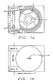
- Fig. 1a shows a top view of the first embodiment of the present invention. It shows two identical actuators 1 . Identical actuators are preferable but they could be of different types as long as they have a same torque. Furthermore it shows a movable lens barrel 2 , which is moved by the two actuators 1 and guided by two ball bearings 3 to achieve minimal friction of the movement of the lens barrel and a carrier 5. The lens barrel 2 is moving up and down with respect to the carrier 5 . The ball bearing system 3 is guiding the lens barrel 2 containing the lens 4 .
- the twin actuators 1 can be smaller of size than a single actuator and fit into the corners of the camera module with minimum extra space requirement because the lens and lens barrel are round and the camera module is rectangular.
- Fig. 1b shows key points of the first embodiment of the present invention.
- the right and left motors/actuators 1 are deployed in the corners on the same side as the ball bearings, thus minimizing the space requirements.
- Fig. 2a shows a more detailed top view of the first embodiment of the present invention. It shows iron and magnets of the twin actuators 1 , the movable lens barrel 2 , having a lens 4 in the middle, two ball bearings 3 , and a carrier 5 of the camera module.
- Fig. 2b shows a side view of the first embodiment of the present invention. It shows coils of one of the two actuators 1 , the lens barrel 2 , having a lens in the middle, one of two ball cages 6 of the ball bearings, and a carrier 5 of the camera module.
- Bidirectional actuators comprising coils wrapped around magnetic metal, preferably iron, and at least one permanent magnet are deployed to move the lens barrels shown in of Figs. 1 a-b and Figs. 2 a-b. ln a preferred embodiment two of such actuators are used to move the lens barrel and the permanent magnet is mounted on the lens barrel and the iron carrying the coils is mounted on the carrier.
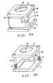
- Figs. 3a-c show a second embodiment of the present invention. Guiding rods, diagonally located at two corners, guide the movable lens barrel. Two preferably identical actuators are located also diagonally at the other corners of the camera module. Adjusting springs can be applied to the guiding rods.
- Fig. 3a shows an assembled camera module with a movable lens barrel 2 , fixed parts 5 , guiding rods 30 , being diagonally deployed, and two bidirectional actuators comprising coils 32 , which are firmly connected to fixed parts 5 of the camera module, and magnets 33 , which are firmly connected to the movable lens barrel 2 .
- the two actuators are also diagonally deployed. Depending upon the currents flowing through the coils 32 , the magnets 33 are moved inside the coils 32 .
- Each of the two guiding rods 30 and each of the two actuators are deployed in a separate corner of the camera module.
- Fig. 3b shows fixed parts 5 with diagonally located guiding rods 30 , springs 31 and diagonally deployed actuator coils 32 .
- This second embodiment of the present invention is using guiding rods 30 instead of ball bearings as used in the first embodiment. It is relying on symmetrical forces to move the lens barrel. Thus a sliding contact bearing seems has been selected.
- the magnets for the actuators are centered inside the coils 32 . Therefore only longitudinal forces are generated by the actuators.
- Fig. 3c shows the movable lens barrel 2 with magnets 33 , which can move inside the coils depending upon the currents through the coils. Via holes 34 are provided for the guiding rods 30 shown in Fig. 3a .
- This configuration of the second embodiment of the present invention does not have a ball bearing system as disclosed with the first embodiment. lnstead it is relying on symmetrical forces by diagonally deployed actuators having a magnet moving inside of coils. Thus a sliding contact bearing seems more appropriate. The magnets are centered inside the coils. So no forces except for longitudinal ones appear from the motors.
- twin-actuator deployment in corners of the camera module allows optimal use of the available space of the rectangular camera module having a round lens. Placing the actuators in the corners of the camera module allows furthermore a maximum lens diameter with the minimal outside dimension of the camera module.
- the present invention yields smaller outside dimensions.
- Fig. 4 illustrates a flowchart of a method invented for camera modules having a movable lens barrel, allowing a maximum lens diameter with minimal outside dimensions.
- a first step 40 describes the provision of a camera module comprising a movable lens barrel and more than one actuator to move the lens barrel.
- the next step 41 illustrates deploying each actuator in a separate corner of the camera module.
- the actuators could be deployed in a first embodiment on a same side of the camera module or be deployed diagonally as described in the second embodiment.
- the camera module invented furthermore comprises an integrated circuit (lC) controlling the actuators of the present invention, an image sensor, and a shutter which also can be used as an aperture.
- This lC also controls one or more motors with integrated position control to move shutter blades of the camera module.
Landscapes
- Physics & Mathematics (AREA)
- General Physics & Mathematics (AREA)
- Optics & Photonics (AREA)
- Lens Barrels (AREA)
Priority Applications (1)
| Application Number | Priority Date | Filing Date | Title |
|---|---|---|---|
| EP10368005A EP2341380A3 (de) | 2009-12-15 | 2010-01-19 | Doppelaktuatorkonfigurierung für ein Kameramodul |
Applications Claiming Priority (2)
| Application Number | Priority Date | Filing Date | Title |
|---|---|---|---|
| EP09368050 | 2009-12-15 | ||
| EP10368005A EP2341380A3 (de) | 2009-12-15 | 2010-01-19 | Doppelaktuatorkonfigurierung für ein Kameramodul |
Publications (2)
| Publication Number | Publication Date |
|---|---|
| EP2341380A2 true EP2341380A2 (de) | 2011-07-06 |
| EP2341380A3 EP2341380A3 (de) | 2011-08-03 |
Family
ID=43530677
Family Applications (1)
| Application Number | Title | Priority Date | Filing Date |
|---|---|---|---|
| EP10368005A Withdrawn EP2341380A3 (de) | 2009-12-15 | 2010-01-19 | Doppelaktuatorkonfigurierung für ein Kameramodul |
Country Status (2)
| Country | Link |
|---|---|
| US (1) | US20110141587A1 (de) |
| EP (1) | EP2341380A3 (de) |
Families Citing this family (5)
| Publication number | Priority date | Publication date | Assignee | Title |
|---|---|---|---|---|
| US20110268434A1 (en) * | 2010-04-28 | 2011-11-03 | Digital Imaging Systems Gmbh | Lens barrel retention systems of a camera module |
| US8320756B2 (en) | 2010-08-10 | 2012-11-27 | Digital Imaging Systems Gmbh | Single actuator configuration for a camera module |
| WO2013005074A1 (en) * | 2011-07-01 | 2013-01-10 | Nokia Corporation | Optical element control |
| US10257433B2 (en) | 2015-04-27 | 2019-04-09 | Microsoft Technology Licensing, Llc | Multi-lens imaging apparatus with actuator |
| CN213423564U (zh) * | 2020-02-10 | 2021-06-11 | 台湾东电化股份有限公司 | 光学元件驱动机构 |
Citations (3)
| Publication number | Priority date | Publication date | Assignee | Title |
|---|---|---|---|---|
| US20070097218A1 (en) | 2005-10-28 | 2007-05-03 | Hon Hai Precision Industry Co., Ltd. | Digital camera module |
| US20080037143A1 (en) | 2006-08-08 | 2008-02-14 | Diostech Co., Ltd. | Lens assembly with actuating means and auto-focus controlling apparatus having the same |
| US7499095B2 (en) | 2004-06-02 | 2009-03-03 | Samsung Electronics Co., Ltd. | Apparatus and method for auto-focusing in a mobile terminal |
Family Cites Families (4)
| Publication number | Priority date | Publication date | Assignee | Title |
|---|---|---|---|---|
| US7505219B2 (en) * | 2006-01-20 | 2009-03-17 | Powergate Optical Inc. | Multi-stage lens driving device |
| KR100843403B1 (ko) * | 2006-12-19 | 2008-07-03 | 삼성전기주식회사 | 렌즈 이송장치 |
| KR100849580B1 (ko) * | 2007-04-10 | 2008-07-31 | 삼성전자주식회사 | 카메라 렌즈 어셈블리 |
| CN101295062B (zh) * | 2007-04-29 | 2010-09-29 | 鸿富锦精密工业(深圳)有限公司 | 镜头模组及相机模组 |
-
2010
- 2010-01-19 EP EP10368005A patent/EP2341380A3/de not_active Withdrawn
- 2010-03-23 US US12/661,755 patent/US20110141587A1/en not_active Abandoned
Patent Citations (3)
| Publication number | Priority date | Publication date | Assignee | Title |
|---|---|---|---|---|
| US7499095B2 (en) | 2004-06-02 | 2009-03-03 | Samsung Electronics Co., Ltd. | Apparatus and method for auto-focusing in a mobile terminal |
| US20070097218A1 (en) | 2005-10-28 | 2007-05-03 | Hon Hai Precision Industry Co., Ltd. | Digital camera module |
| US20080037143A1 (en) | 2006-08-08 | 2008-02-14 | Diostech Co., Ltd. | Lens assembly with actuating means and auto-focus controlling apparatus having the same |
Also Published As
| Publication number | Publication date |
|---|---|
| US20110141587A1 (en) | 2011-06-16 |
| EP2341380A3 (de) | 2011-08-03 |
Similar Documents
| Publication | Publication Date | Title |
|---|---|---|
| CN110352371B (zh) | 减少高度容余的折叠摄像装置 | |
| JP6138969B2 (ja) | カメラモジュール | |
| US7570880B2 (en) | Auto focus control apparatus for camera module | |
| US8320756B2 (en) | Single actuator configuration for a camera module | |
| US9448382B2 (en) | Electromagnetic actuators for digital cameras | |
| US8086099B2 (en) | Camera module having a low-friction movable lens | |
| KR100582746B1 (ko) | 영상 촬영 장치 | |
| KR20180119595A (ko) | 렌즈 구동 장치, 카메라 모듈, 및 카메라 탑재 장치 | |
| EP2341380A2 (de) | Doppelaktuatorkonfigurierung für ein Kameramodul | |
| JP2009058601A (ja) | レンズ駆動装置及び撮像装置並びに携帯端末 | |
| KR20110068504A (ko) | 저가 제작 및 소형화가 가능한 렌즈 액츄에이터 | |
| US20060228099A1 (en) | Digital camera with electromagnetic focusing module | |
| US8180211B2 (en) | Drop detection using lens position sensing of camera module | |
| US8462452B2 (en) | Electromagnetic driving device | |
| US20110268434A1 (en) | Lens barrel retention systems of a camera module | |
| KR100466508B1 (ko) | 정보통신기기용 소형 카메라장치 | |
| JP2008096705A (ja) | レンズ駆動装置及び撮像装置並びに携帯端末 | |
| JP2005070609A (ja) | レンズ駆動装置の駆動方法およびレンズ駆動装置ならびにカメラ | |
| KR100562721B1 (ko) | 통신기기용 소형 카메라장치 | |
| JP2007148354A (ja) | レンズ駆動装置 | |
| JP4711121B2 (ja) | レンズ装置、およびレンズ装置を有する撮像装置 | |
| JP2006094581A (ja) | 駆動装置、および撮像装置 | |
| KR101904419B1 (ko) | 광학 요소 이송 장치 및 이를 구비한 촬상 장치 | |
| JP2006178006A (ja) | 撮像用レンズ装置 | |
| JP2005275269A (ja) | レンズ鏡筒および撮像装置 |
Legal Events
| Date | Code | Title | Description |
|---|---|---|---|
| PUAI | Public reference made under article 153(3) epc to a published international application that has entered the european phase |
Free format text: ORIGINAL CODE: 0009012 |
|
| PUAL | Search report despatched |
Free format text: ORIGINAL CODE: 0009013 |
|
| AK | Designated contracting states |
Kind code of ref document: A2 Designated state(s): AT BE BG CH CY CZ DE DK EE ES FI FR GB GR HR HU IE IS IT LI LT LU LV MC MK MT NL NO PL PT RO SE SI SK SM TR |
|
| AX | Request for extension of the european patent |
Extension state: AL BA RS |
|
| AK | Designated contracting states |
Kind code of ref document: A3 Designated state(s): AT BE BG CH CY CZ DE DK EE ES FI FR GB GR HR HU IE IS IT LI LT LU LV MC MK MT NL NO PL PT RO SE SI SK SM TR |
|
| AX | Request for extension of the european patent |
Extension state: AL BA RS |
|
| RIC1 | Information provided on ipc code assigned before grant |
Ipc: G02B 13/00 20060101ALI20110630BHEP Ipc: G02B 7/08 20060101AFI20110630BHEP |
|
| RAP1 | Party data changed (applicant data changed or rights of an application transferred) |
Owner name: DIGITAL IMAGING SYSTEMS GMBH |
|
| 19U | Interruption of proceedings before grant |
Effective date: 20110930 |
|
| 19W | Proceedings resumed before grant after interruption of proceedings |
Effective date: 20120801 |
|
| STAA | Information on the status of an ep patent application or granted ep patent |
Free format text: STATUS: THE APPLICATION IS DEEMED TO BE WITHDRAWN |
|
| 18D | Application deemed to be withdrawn |
Effective date: 20121205 |