EP2341744A2 - Schéma de contrôle de bout en bout à faible gigue pour communications isochrones basées sur des informations d'horodatage de transmetteur - Google Patents
Schéma de contrôle de bout en bout à faible gigue pour communications isochrones basées sur des informations d'horodatage de transmetteur Download PDFInfo
- Publication number
- EP2341744A2 EP2341744A2 EP10196165A EP10196165A EP2341744A2 EP 2341744 A2 EP2341744 A2 EP 2341744A2 EP 10196165 A EP10196165 A EP 10196165A EP 10196165 A EP10196165 A EP 10196165A EP 2341744 A2 EP2341744 A2 EP 2341744A2
- Authority
- EP
- European Patent Office
- Prior art keywords
- time stamp
- time
- data
- payload
- transmitter
- Prior art date
- Legal status (The legal status is an assumption and is not a legal conclusion. Google has not performed a legal analysis and makes no representation as to the accuracy of the status listed.)
- Granted
Links
Images


Classifications
-
- H—ELECTRICITY
- H04—ELECTRIC COMMUNICATION TECHNIQUE
- H04J—MULTIPLEX COMMUNICATION
- H04J3/00—Time-division multiplex systems
- H04J3/02—Details
- H04J3/06—Synchronising arrangements
- H04J3/0635—Clock or time synchronisation in a network
- H04J3/0638—Clock or time synchronisation among nodes; Internode synchronisation
- H04J3/0652—Synchronisation among time division multiple access [TDMA] nodes, e.g. time triggered protocol [TTP]
- H04J3/0655—Synchronisation among time division multiple access [TDMA] nodes, e.g. time triggered protocol [TTP] using timestamps
-
- H—ELECTRICITY
- H04—ELECTRIC COMMUNICATION TECHNIQUE
- H04J—MULTIPLEX COMMUNICATION
- H04J3/00—Time-division multiplex systems
- H04J3/02—Details
- H04J3/06—Synchronising arrangements
- H04J3/062—Synchronisation of signals having the same nominal but fluctuating bit rates, e.g. using buffers
-
- H—ELECTRICITY
- H04—ELECTRIC COMMUNICATION TECHNIQUE
- H04R—LOUDSPEAKERS, MICROPHONES, GRAMOPHONE PICK-UPS OR LIKE ACOUSTIC ELECTROMECHANICAL TRANSDUCERS; ELECTRIC HEARING AIDS; PUBLIC ADDRESS SYSTEMS
- H04R2420/00—Details of connection covered by H04R, not provided for in its groups
- H04R2420/07—Applications of wireless loudspeakers or wireless microphones
-
- H—ELECTRICITY
- H04—ELECTRIC COMMUNICATION TECHNIQUE
- H04R—LOUDSPEAKERS, MICROPHONES, GRAMOPHONE PICK-UPS OR LIKE ACOUSTIC ELECTROMECHANICAL TRANSDUCERS; ELECTRIC HEARING AIDS; PUBLIC ADDRESS SYSTEMS
- H04R25/00—Electric hearing aids
- H04R25/55—Electric hearing aids using an external connection, either wireless or wired
- H04R25/554—Electric hearing aids using an external connection, either wireless or wired using a wireless connection, e.g. between microphone and amplifier or using Tcoils
Definitions
- the present invention relates to ways to control the jitter caused by different arrival times of data, due in part to different paths or different components that may introduce delay. More particularly, the present invention relates to latency control for isochronous data streams in order to reduce jitter in applications that may require paths through several intermediary nodes before reaching a final destination.
- the management of delay between the audio signal at the input of a transmitter and the audio signal at the output of the receiver(s) is important to avoid distortion of the sound.
- the delay between the audio signal at the input and the audio signal at the output should be the same for every receiving node.
- the sound direction information will be significantly distorted when the latency for both signal paths is different.
- an accurate indication of the position of the sound source is a significant parameter for consideration.
- a time delay difference between the left and right audio signal should be typically less than 5 to 10 us.
- latency control mechanisms are often comprised of a series of buffers that are used to store a certain predetermined amount of data in accordance with typical network delays so that the data provided to a receiver can come from the buffer in the event there is a delay in receiving data.
- each loudspeaker outputs roughly the same sample.
- the virtual sound source position or stereo image is no longer stable as delays of sound arrival in the human ear for sound produced by each of the loudspeakers create the virtual sound source illusion.
- the aforementioned WO publication proposes that the amount of buffer filling can compensate for end-to-end delays, by measuring items such as an input time measurement.
- An input time measuring unit yields a measurement
- a delay control unit controls the delay by controlling the data rate conversion on the basis of a filling measurement of the buffers and the input time measurement.
- a read time measuring component is arranged to measure a read time instant and yields a read time measurement of a first data unit in which the delay control unit is arranged to control the data rate conversion on the basis of the read time measurement.
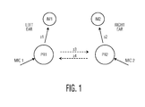
- FIG. 1 shows an example of a hearing aid application in which implant IM1 is arranged in the left ear and implant IM2 is arranged in the right ear.
- both hearing aids for the left and right ears work independently of each other.
- processor PR1 captures sound from microphone MIC 1 and transmits this audio stream to implant IM1 via stream al.
- right ear processor PR2 captures sound from microphone MIC2 and transmits this particular audio stream to implant IM2 via stream a2.
- audio stream a1 should have the same latency as audio stream a2.
- the signals of microphones MIC1 and MIC2 are combined for audio beam forming that results in a better hearing experience.
- additional streams a3 and a4 are needed so that each processor can combine both microphone signals and send the processed signals a1 and a2 to the respective implants.
- These streams are potentially transmitted via different physical layers, e.g. Magnetic Induction for al and a2, and RF for a3 and a4.
- Processor PR1 will receive the signal of MIC2 with a certain delay compared to the signal of MIC1 since it has to be transmitted by PR2 via channel a4. Therefore the signal of MIC1 has to be delayed also in order to align it with the signal of MIC2. The processed signal will be transmitted via a1 to IM1 and this introduces an additional delay. Similarly, processor PR2 receives the signal of MIC1 via a3 with a certain delay and it has to delay the signal of MIC2 before combining it with the signal of MIC1 and sending the processed signal via a2 device IM2.
- the end-to-end delay between all source and destination devices should be the same:
- This end-to-end delay is preferably constant and controllable. It should also have a low time jitter since otherwise the audio signal at the destination side will be significantly distorted.
- Embodiments of the present invention provide a latency control mechanism and method that provides a very low jitter time on the end-to-end latency, and renders the latency controllable within a given range, depending on the constraints imposed by the implementation.
- the present invention is applicable in many other applications beyond that of wireless applications, and can be used for all applications that have to communicate isochronous data streams with a controlled end-to-end latency.
- an isochronous data stream is organized into frames and/or super frames with well-defined time references, which are known by all devices along the path followed by the data stream.
- time references can be, e.g. defined by fixed data patterns in the frame such as the frame synch word.
- the time relation (time offset) between the time reference at the transmitter/source side and the time reference at the receiver destination side should be known by the receiver.
- a time stamp is taken at the local transmitter time reference and this time stamp information is transmitted together with the isochronous data stream.
- a time stamp is taken at the local receiver time reference.
- This time stamp information combined with the transmitter time stamp, received together with the data stream, and the known time offset between the receiver and the transmitter time reference, allows implementing a constant end-to-end latency control mechanism.
- the time stamp information is expressed as a number of audio samples. It contains an integer part, representing the number of audio samples received so far, and a fractional part, representing the fraction of the audio sample that has already entered the transmitter or left the receiver when the time stamp is taken.
- FIG. 2 illustrates an exemplary wireless audio system for hearing aid systems utilizing the latency control mechanism according to the present invention.
- this particular wireless link is assumed to have a channel bit rate of 298kbps, but this rate is only provided for illustrative purposes.
- the audio samples are transmitted by means of data frames according to, in this example, a Time Division Multiple Access (TDMA) mechanism. These data frames have a length of one or more time slots and are organized in a superframe structure, as shown, for example, in FIG. 3 .
- TDMA Time Division Multiple Access
- the digital audio stream is encoded to obtain a 4:1 bit rate reduction. It should be noted that such encoding is optional.
- the concept of the present invention does not depend on the method used to encode the data stream.
- a typical frame and time slot allocation scheme for the example of FIG. 2 is shown in FIG. 4 .
- the incoming audio samples are counted with a high-resolution fractional sample counter, encoded by the payload encoder and written to the TX buffer.
- the Tx control block 205 handles the transfer between both clock domains.
- the transmitter 200 includes a data sample counter 225 for counting the input data samples.
- Payload encoder 220 encodes input data samples into payload data.
- Write control unit 224 controls the storage of payload data.
- a transmit buffer 222 stores the payload data to be transmitted.
- Transmit control unit 205 generates a time reference TrefTx and a related time synchronization symbol, and the transmit control unit 205 takes a snapshot TxScnt of the transmit sample counter 225 at the aforementioned time reference.
- Transmit time stamp unit 210 generates a transmit time stamp information based on the value TxScnt.
- Transmit unit 201 for transmitting the time reference symbol, the payload data representing the input data samples, and the related time stamp information.
- a time synchronization unit 303 detects the transmitted time reference symbol, generating a time reference Tref Rx, which has a fixed and known time relationship with respect to TrefTx, and provides the time reference Tref Rx to time stamp unit 310.
- a receive unit 301 for receiving the time reference symbol, the payload data and the related time stamp information from transmit unit 201.
- RX DPLL and Latency control block 315 generates an estimate FsTxe of the data sample rate FsTx at the input of the transmitter, based on the received transmitter time stamp, on the receiver time stamp generated by time stamp unit 310 and on a target latency between the transmitter timestamp and the receiver time stamp.
- a fractional sample counter 325 counts the number of data samples provided to the receiver output, based on the estimated sample rate FsTxe of the input data rate FsTx.
- Time stamp unit 310 generates a receiver time stamp by taking a snapshot RxScnt of sample counter 325 at time instant TrefRx, and providing this time stamp information to latency control block 315.
- Read control unit 324 controls the transfer of payload data from receive buffer 305 to a payload decoder 320 and transfers the output of payload decoder 320 to the receiver output at the rate determined by sample counter 325.
- Payload decoder 320 converts the payload data from receive buffer 305 to a representation of the data samples provided at the input of the transmitter.
- the block RX DPLL and latency control 315 adjusts the reading moment and position from the RX buffer 305 so that the delay between the time stamp taken at the source side 200 by the transmitter time stamp unit 210, and the time stamp taken at the receiver side 300 by receiver time stamp unit 310 is constant and equal to a given value.
- the RX DPLL block 315 based on the included time stamp information, the RX DPLL block 315 generates an estimated value FsTxe of the audio sample rate FsTx at the source side.
- the payload decoder 320 reads the compressed data from one RX buffer 305 and provides decoded audio samples at the estimated source sample FsTxe.
- the samples leaving the payload decoder 320 are counted with a high resolution fractional sample counter 325, similar to the sample counter 225 used on the transmitter side 200.
- This counter 325 is sampled at instant TrefRx, which has a fixed and known time relationship with respect to TrefTx, e.g. the position of the correlation peak of the frame synch word.
- the block RX DPLL and latency control 315 adjusts the reading from the RX buffer in such a way that the delay between the time stamp taken at the TX side 200 by the time stamp unit 210, and the time stamp taken at the RX side 300 by time stamp unit 310 is constant and equal to a given value.
- a sample rate converter 330 can be inserted between the payload decoder 320 and the digital audio output, as indicated at the right hand side of FIG. 2 .
- FIG. 3 illustrates an example of a superframe structure 3100 according to the present invention.
- the start of the superframe is indicated by a beacon frame 3050.
- data frames and time slots are allocated such that there is sufficient capacity to support the rate of the encoded audio stream.
- the distance between the different frames does not have to be constant, but the allocated time slots should be distributed as evenly as possible over the superframe in order to obtain a low end-to-end latency.
- FIG. 4 shows an exemplary frame allocation scheme for two audio channels of 64 kps in this example.
- the audio stream parameters are an audio sample rate of 16 kHz and an encoded audio rate of 64 kbps.
- the superframe parameters include a channel rate of 298 kbps, a time slot length of 322.15us, a superframe length of 82.47 ms and 256 timeslots per superframe.
- channel 10 is the beacon channel
- audio channel a1 is allocated to channel 1
- audio channel a2 is allocated to channel 2.
- Channel 3 is free in this example.
- the sample counter 225 monitors the digital audio input and counts the number of samples received.
- the sample counter 225 may have, for example, a high resolution, by counting the bit clock of the serial audio interface instead of the word clock.
- the audio samples are sent to the payload encoder 220, which stores the encoded samples in the TX buffer 222 under the control of the write control unit 224.
- the write control unit 224 introduces a delay ofNenc audio samples between the digital audio input and the encoded audio data written to the TX buffer 222, representing the delay introduced by the audio encoder or by any other data processing.
- a snapshot TxScnt of the TX sample counter is taken and provided to the TX control unit 205. Also, the audio sample index Asidx of the first byte to be transmitted and the number of audio bytes Nab to be transmitted are determined. If the payload encoder 220 packs two audio samples in one byte, the audio sample index Asidx increments at half the sample rate.
- the TX control unit 205 determines the number of audio bytes Nab that will be transmitted in the current audio frame. The TX control unit 205 will try to transmit all data that is present in the TX buffer 222 when the time stamp is taken.
- the value of TimeOffset will be zero or it will contain only the fractional part of the time stamp. When not all data present in the TX buffer can be transmitted, the integer part of TimeOffset will indicate the number of (encoded) audio samples that still needs to be transmitted.
- the receiver can use the audio sample index Asidx to resynchronize the write pointer to the RX buffer after a loss of one or more audio frames.
- a digital phased locked loop (DPLL) 315 can be used to estimate the audio sample rate (FsTxe) seen at the input of the transmitter (FsTx).
- FsTxe audio sample rate seen at the input of the transmitter
- the RX buffer read rate proportional to FsTxe
- the RX buffer write rate which is proportional to FsTx.
- the TX control parameters Asidx and Nab are used to write the received audio data bytes in the RX buffer at a location that is synchronized with their location in the TX buffer.
- Parameters Asidx, Nab, TimeOffset and Nenc are used to calculate the timestamp TxScnt at a transmitter side by means of Equation (4.1).
- the RX DPLL 315 generates an estimate FsTxe of the audio sample rate at the transmitter side from its local reference clock. This estimated sample rate drives the RX sample counter 325, which counts the number of samples coming out of the payload decoder 320.
- TrefRx which can be determined by the correlation peak of the frame word synch
- a snapshot of the sample counter RxScnt is taken.
- the time difference between TrefRx and TrefTx is assumed to be constant. The time difference is either known by design or can be determined when the channel for the audio stream is created, for example, by measuring the path delay.
- Latency TxScnt + Delta Tref - RxScnt
- the latency control algorithm will adjust the estimated audio sample rate FsTxe such that the latency, calculated according to equation (4.3), becomes equal to the TargetLatency for that channel.
- Encoded audio bytes are read from the RX buffer under control of the read control unit and applied to the payload decoder.
- the decoded audio samples are made available at the sample rate FsTxe and updated synchronously with the RX sample counter. If the receiver is master of the digital audio output bus, these audio samples can be sent directly to the digital audio output. Otherwise, the sample rate first has to be converted to the required value.
- FIG. 5A shows an example of a typical audio latency transient response, expressed as number of audio samples versus time (in ms) according to the present invention
- FIG. 5B shows the Audio Latency Jitter, expressed as fractional number of audio samples versus time (in ms).
- the present invention provides at least the following benefits and advantages in that a predictable, fixed end-to-end latency for isochronous data streams can be guaranteed.
- Known state-of-the-art latency control mechanisms make use of the buffer filling information at the receiver side, and such known mechanisms cannot take into account differences in propagation delay between the transmitter and the different receiving nodes.
- the receivers are able to generate a constant end-to-end delay for the isochronous data stream, independent of path delay tolerances.
- time stamp information that is added and the overhead it introduces versus the latency control accuracy and the latency jitter.
- the time stamp information By encoding the time stamp information as an audio sample count with integer and fractional parts, it becomes very easy to resynchronize the receive buffer pointer when packets are lost during transport in the communication channel.
- the latency control loop By encoding the time stamp information with a high resolution, the latency control loop can reach the target latency within a fraction of an audio sample period and with a very small residual time jitter.
- the above-described methods according to the present invention can be realized in hardware or as software or computer code that can be stored as machine readable code in a medium such as a ROM, a RAM, a floppy disk, a hard disk, a flash memory, or a magneto-optical disk, or downloaded over a network, so that the methods described herein can be rendered in such software using a general purpose microprocessor, general purpose computer, or a special processor or in programmable or dedicated hardware, such as an ASIC or FPGA.
- the computer, the processor or the programmable hardware include memory components, e.g., RAM, ROM, Flash, etc. that may store or receive software or computer code that when accessed and executed by the computer, processor or hardware implement the processing methods described herein.
- memory components e.g., RAM, ROM, Flash, etc. that may store or receive software or computer code that when accessed and executed by the computer, processor or hardware implement the processing methods described herein.
- a latency control mechanism for a communication system which provides a known constant end-to-end delay between an audio source and one or more end node destinations, even in the case where different paths are used to reach the end nodes.
- a very low jitter time on the end-to-end latency is obtained, and the latency is controllable within a given range in dependence on the constraints imposed by the implementation.
- a block RX DPLL and latency control unit 315 adjusts the reading moment and position from the RX buffer 305 so that a delay between the time stamp taken at the source side 200 by the transmitter time stamp unit 210, and the time stamp taken at the receiver side 300 by receiver time stamp unit 310 is constant and equal to a given value.
Landscapes
- Engineering & Computer Science (AREA)
- Computer Networks & Wireless Communication (AREA)
- Signal Processing (AREA)
- Computer Hardware Design (AREA)
- Communication Control (AREA)
- Synchronisation In Digital Transmission Systems (AREA)
- Data Exchanges In Wide-Area Networks (AREA)
Applications Claiming Priority (1)
| Application Number | Priority Date | Filing Date | Title |
|---|---|---|---|
| US12/649,493 US8208500B2 (en) | 2009-12-30 | 2009-12-30 | Low-jitter end-to-end latency control scheme for isochronous communications based on transmitter timestamp information |
Publications (3)
| Publication Number | Publication Date |
|---|---|
| EP2341744A2 true EP2341744A2 (fr) | 2011-07-06 |
| EP2341744A3 EP2341744A3 (fr) | 2015-04-29 |
| EP2341744B1 EP2341744B1 (fr) | 2019-02-20 |
Family
ID=43663494
Family Applications (1)
| Application Number | Title | Priority Date | Filing Date |
|---|---|---|---|
| EP10196165.4A Active EP2341744B1 (fr) | 2009-12-30 | 2010-12-21 | Schéma de contrôle de bout en bout à faible gigue pour communications isochrones basées sur des informations d'horodatage de transmetteur |
Country Status (3)
| Country | Link |
|---|---|
| US (1) | US8208500B2 (fr) |
| EP (1) | EP2341744B1 (fr) |
| CN (1) | CN102118243B (fr) |
Cited By (1)
| Publication number | Priority date | Publication date | Assignee | Title |
|---|---|---|---|---|
| EP2897384A3 (fr) * | 2014-01-15 | 2015-08-26 | Jeffrey Paul Solum | Procédé et appareil de rendu audio dans des prothèses auditives sans fil |
Families Citing this family (12)
| Publication number | Priority date | Publication date | Assignee | Title |
|---|---|---|---|---|
| US8046623B2 (en) * | 2009-01-12 | 2011-10-25 | Mediatek Inc. | Timing recovery apparatus and method thereof |
| EP2424274B1 (fr) | 2010-08-25 | 2018-08-01 | Nxp B.V. | Dispositif de radiodiffusion, récepteur pour recevoir les données radiodiffusées et procédé pour initier la radiodiffusion |
| EP2482596B1 (fr) | 2011-01-26 | 2013-09-04 | Nxp B.V. | Synchronisation de dispositifs sans fil |
| US20130070751A1 (en) * | 2011-09-20 | 2013-03-21 | Peter Atwal | Synchronization of time in a mobile ad-hoc network |
| US9471090B2 (en) | 2012-11-21 | 2016-10-18 | Starkey Laboratories, Inc. | Method and apparatus for synchronizing hearing instruments via wireless communication |
| DE102016106105A1 (de) * | 2016-04-04 | 2017-10-05 | Sennheiser Electronic Gmbh & Co. Kg | Drahtlos-Mikrofon- und/oder In-Ear-Monitoring-System und Verfahren zum Steuern eines Drahtlos-Mikrofon- und/oder In-Ear-Monitoring-Systems |
| US10368174B2 (en) | 2016-06-28 | 2019-07-30 | Semiconductor Components Industries, Llc | Distributed phase locked loop in hearing instruments |
| CN110879387B (zh) * | 2019-12-17 | 2021-10-15 | 成都华创电科信息技术有限公司 | 一种基于无线电宽带信号测距仪 |
| CN114070442A (zh) * | 2020-07-30 | 2022-02-18 | 上海诺基亚贝尔股份有限公司 | 不同通信方向上的呈现时间偏移量的自动对齐 |
| US11477600B1 (en) * | 2021-05-27 | 2022-10-18 | Qualcomm Incorporated | Spatial audio data exchange |
| CN114401255B (zh) * | 2022-03-25 | 2022-08-23 | 广州迈聆信息科技有限公司 | 一种音频信号对齐方法、装置、会议终端及存储介质 |
| CN115314144B (zh) * | 2022-07-28 | 2025-04-25 | 烽火通信科技股份有限公司 | 一种otn中以太业务的传输时延控制方法及系统 |
Citations (1)
| Publication number | Priority date | Publication date | Assignee | Title |
|---|---|---|---|---|
| WO2005013639A2 (fr) | 2003-08-05 | 2005-02-10 | Koninklijke Philips Electronics N.V. | Systeme de gestion de tampon, recepteur audio numerique, ecouteurs, haut-parleur et procede de gestion de tampon |
Family Cites Families (8)
| Publication number | Priority date | Publication date | Assignee | Title |
|---|---|---|---|---|
| BE1000415A7 (nl) | 1987-03-18 | 1988-11-22 | Bell Telephone Mfg | Asynchroon op basis van tijdsverdeling werkend communicatiesysteem. |
| DE69936912T2 (de) * | 1998-12-02 | 2008-05-15 | Nxp B.V. | System und verfahren zur erzeugung von einem echtzeitsignal |
| SE521462C2 (sv) * | 1999-07-08 | 2003-11-04 | Ericsson Telefon Ab L M | Förfarande och anordning för sändning av information i ett telekommunikationssystem |
| JP4577816B2 (ja) * | 2001-06-29 | 2010-11-10 | トムソン ライセンシング | 非同期ディジタル・ホーム・ネットワークにおけるマルチメディア・ジッタ除去 |
| US7024640B2 (en) * | 2001-06-29 | 2006-04-04 | Koninklijke Philips Electronics N.V. | Integrated circuit cell identification |
| US7315622B2 (en) * | 2002-06-27 | 2008-01-01 | Nxp B.V. | Robust method for achieving audio/video synchronization in MPEG decoders in personal video recording applications |
| US7668243B2 (en) * | 2004-05-18 | 2010-02-23 | Texas Instruments Incorporated | Audio and video clock synchronization in a wireless network |
| US7831728B2 (en) * | 2005-01-14 | 2010-11-09 | Citrix Systems, Inc. | Methods and systems for real-time seeking during real-time playback of a presentation layer protocol data stream |
-
2009
- 2009-12-30 US US12/649,493 patent/US8208500B2/en active Active
-
2010
- 2010-12-21 EP EP10196165.4A patent/EP2341744B1/fr active Active
- 2010-12-29 CN CN201010621685.3A patent/CN102118243B/zh active Active
Patent Citations (1)
| Publication number | Priority date | Publication date | Assignee | Title |
|---|---|---|---|---|
| WO2005013639A2 (fr) | 2003-08-05 | 2005-02-10 | Koninklijke Philips Electronics N.V. | Systeme de gestion de tampon, recepteur audio numerique, ecouteurs, haut-parleur et procede de gestion de tampon |
Cited By (2)
| Publication number | Priority date | Publication date | Assignee | Title |
|---|---|---|---|---|
| EP2897384A3 (fr) * | 2014-01-15 | 2015-08-26 | Jeffrey Paul Solum | Procédé et appareil de rendu audio dans des prothèses auditives sans fil |
| US9661425B2 (en) | 2014-01-15 | 2017-05-23 | Starkey Laboratories, Inc. | Method and apparatus for rendering audio in wireless hearing instruments |
Also Published As
| Publication number | Publication date |
|---|---|
| US8208500B2 (en) | 2012-06-26 |
| CN102118243B (zh) | 2014-04-09 |
| CN102118243A (zh) | 2011-07-06 |
| EP2341744B1 (fr) | 2019-02-20 |
| US20110158264A1 (en) | 2011-06-30 |
| EP2341744A3 (fr) | 2015-04-29 |
Similar Documents
| Publication | Publication Date | Title |
|---|---|---|
| US8208500B2 (en) | Low-jitter end-to-end latency control scheme for isochronous communications based on transmitter timestamp information | |
| EP3644661B1 (fr) | Procédé de synchronisation d'horloges de synchronisation d'un dispositif bluetooth | |
| EP3609207B1 (fr) | Système de rendu audio | |
| KR101178252B1 (ko) | 다수의 데이터 싱크들을 위한 신호들의 동기화 | |
| US20210067874A1 (en) | Method, device, loudspeaker equipment and wireless headset for playing audio synchronously | |
| CN111918261A (zh) | 蓝牙音频设备同步播放方法、系统及蓝牙音频主、从设备 | |
| EP2437416B1 (fr) | Prédicteur d'horodatage pour paquets sur un protocole synchrone | |
| US12328692B2 (en) | Synchronization of audio streams and sampling rate for wireless communication | |
| DK2897384T3 (en) | Method and device for audio reproduction in wireless hearing aids | |
| CN113612564B (zh) | 一种报文处理的方法和网络设备 | |
| CN117596516A (zh) | 音频播放系统 | |
| EP1585243A1 (fr) | Méthode et dispositif de demultiplexage de trains de signaux numériques | |
| CN110838854A (zh) | 蓝牙无线装置以及使用于无线装置的方法 | |
| JP3673268B1 (ja) | ジッタ補正装置 | |
| JP2005505988A (ja) | デジタル・データ同期化の方法および装置 | |
| US20030063684A1 (en) | System and method for transmission of digital information of varying sample rates over a synchronous network | |
| EP4026022B1 (fr) | Amélioration de synchronisation pour système de haut-parleurs intelligents | |
| JP7105849B2 (ja) | 異なるブルートゥース回路によるオーディオ再生を同期させ続けることが可能なマルチ構成要員型ブルートゥース装置における、ブルートゥース主回路およびブルートゥース副回路 | |
| CN106209343B (zh) | 同步化向多个可移动音频终端发送的数字信号的播放 | |
| EP4626029A1 (fr) | Procédé de synchronisation de dispositifs électroniques connectés sans fil et dispositif sans fil | |
| WO2019136094A1 (fr) | Adaptation de flux au temps de latence | |
| CN117750490A (zh) | 一种无线音频传输方法、多麦克风系统及装置 | |
| CN117834597A (zh) | 一种基于arm的低延迟网络音频传输系统和方法 | |
| US20120331176A1 (en) | Method for transport and recovery of client clocking across asynchronous server networks | |
| JP2014103557A (ja) | データ受信装置、dpll装置及びデータ受信装置制御方法 |
Legal Events
| Date | Code | Title | Description |
|---|---|---|---|
| PUAI | Public reference made under article 153(3) epc to a published international application that has entered the european phase |
Free format text: ORIGINAL CODE: 0009012 |
|
| AK | Designated contracting states |
Kind code of ref document: A2 Designated state(s): AL AT BE BG CH CY CZ DE DK EE ES FI FR GB GR HR HU IE IS IT LI LT LU LV MC MK MT NL NO PL PT RO RS SE SI SK SM TR |
|
| AX | Request for extension of the european patent |
Extension state: BA ME |
|
| 17P | Request for examination filed |
Effective date: 20140331 |
|
| PUAL | Search report despatched |
Free format text: ORIGINAL CODE: 0009013 |
|
| AK | Designated contracting states |
Kind code of ref document: A3 Designated state(s): AL AT BE BG CH CY CZ DE DK EE ES FI FR GB GR HR HU IE IS IT LI LT LU LV MC MK MT NL NO PL PT RO RS SE SI SK SM TR |
|
| AX | Request for extension of the european patent |
Extension state: BA ME |
|
| RIC1 | Information provided on ipc code assigned before grant |
Ipc: H04J 3/06 20060101ALI20150324BHEP Ipc: H04W 56/00 20090101AFI20150324BHEP |
|
| RBV | Designated contracting states (corrected) |
Designated state(s): AL AT BE BG CH CY CZ DE DK EE ES FI FR GB GR HR HU IE IS IT LI LT LU LV MC MK MT NL NO PL PT RO RS SE SI SK SM TR |
|
| STAA | Information on the status of an ep patent application or granted ep patent |
Free format text: STATUS: EXAMINATION IS IN PROGRESS |
|
| 17Q | First examination report despatched |
Effective date: 20180111 |
|
| GRAP | Despatch of communication of intention to grant a patent |
Free format text: ORIGINAL CODE: EPIDOSNIGR1 |
|
| STAA | Information on the status of an ep patent application or granted ep patent |
Free format text: STATUS: GRANT OF PATENT IS INTENDED |
|
| INTG | Intention to grant announced |
Effective date: 20180730 |
|
| GRAJ | Information related to disapproval of communication of intention to grant by the applicant or resumption of examination proceedings by the epo deleted |
Free format text: ORIGINAL CODE: EPIDOSDIGR1 |
|
| STAA | Information on the status of an ep patent application or granted ep patent |
Free format text: STATUS: EXAMINATION IS IN PROGRESS |
|
| GRAP | Despatch of communication of intention to grant a patent |
Free format text: ORIGINAL CODE: EPIDOSNIGR1 |
|
| STAA | Information on the status of an ep patent application or granted ep patent |
Free format text: STATUS: GRANT OF PATENT IS INTENDED |
|
| GRAS | Grant fee paid |
Free format text: ORIGINAL CODE: EPIDOSNIGR3 |
|
| INTC | Intention to grant announced (deleted) | ||
| INTG | Intention to grant announced |
Effective date: 20181115 |
|
| GRAA | (expected) grant |
Free format text: ORIGINAL CODE: 0009210 |
|
| STAA | Information on the status of an ep patent application or granted ep patent |
Free format text: STATUS: THE PATENT HAS BEEN GRANTED |
|
| AK | Designated contracting states |
Kind code of ref document: B1 Designated state(s): AL AT BE BG CH CY CZ DE DK EE ES FI FR GB GR HR HU IE IS IT LI LT LU LV MC MK MT NL NO PL PT RO RS SE SI SK SM TR |
|
| REG | Reference to a national code |
Ref country code: GB Ref legal event code: FG4D |
|
| REG | Reference to a national code |
Ref country code: CH Ref legal event code: EP |
|
| REG | Reference to a national code |
Ref country code: DE Ref legal event code: R096 Ref document number: 602010057030 Country of ref document: DE |
|
| REG | Reference to a national code |
Ref country code: AT Ref legal event code: REF Ref document number: 1099903 Country of ref document: AT Kind code of ref document: T Effective date: 20190315 |
|
| REG | Reference to a national code |
Ref country code: IE Ref legal event code: FG4D |
|
| REG | Reference to a national code |
Ref country code: LT Ref legal event code: MG4D Ref country code: NL Ref legal event code: MP Effective date: 20190220 |
|
| PG25 | Lapsed in a contracting state [announced via postgrant information from national office to epo] |
Ref country code: FI Free format text: LAPSE BECAUSE OF FAILURE TO SUBMIT A TRANSLATION OF THE DESCRIPTION OR TO PAY THE FEE WITHIN THE PRESCRIBED TIME-LIMIT Effective date: 20190220 Ref country code: SE Free format text: LAPSE BECAUSE OF FAILURE TO SUBMIT A TRANSLATION OF THE DESCRIPTION OR TO PAY THE FEE WITHIN THE PRESCRIBED TIME-LIMIT Effective date: 20190220 Ref country code: LT Free format text: LAPSE BECAUSE OF FAILURE TO SUBMIT A TRANSLATION OF THE DESCRIPTION OR TO PAY THE FEE WITHIN THE PRESCRIBED TIME-LIMIT Effective date: 20190220 Ref country code: NO Free format text: LAPSE BECAUSE OF FAILURE TO SUBMIT A TRANSLATION OF THE DESCRIPTION OR TO PAY THE FEE WITHIN THE PRESCRIBED TIME-LIMIT Effective date: 20190520 Ref country code: PT Free format text: LAPSE BECAUSE OF FAILURE TO SUBMIT A TRANSLATION OF THE DESCRIPTION OR TO PAY THE FEE WITHIN THE PRESCRIBED TIME-LIMIT Effective date: 20190620 |
|
| PG25 | Lapsed in a contracting state [announced via postgrant information from national office to epo] |
Ref country code: HR Free format text: LAPSE BECAUSE OF FAILURE TO SUBMIT A TRANSLATION OF THE DESCRIPTION OR TO PAY THE FEE WITHIN THE PRESCRIBED TIME-LIMIT Effective date: 20190220 Ref country code: NL Free format text: LAPSE BECAUSE OF FAILURE TO SUBMIT A TRANSLATION OF THE DESCRIPTION OR TO PAY THE FEE WITHIN THE PRESCRIBED TIME-LIMIT Effective date: 20190220 Ref country code: RS Free format text: LAPSE BECAUSE OF FAILURE TO SUBMIT A TRANSLATION OF THE DESCRIPTION OR TO PAY THE FEE WITHIN THE PRESCRIBED TIME-LIMIT Effective date: 20190220 Ref country code: LV Free format text: LAPSE BECAUSE OF FAILURE TO SUBMIT A TRANSLATION OF THE DESCRIPTION OR TO PAY THE FEE WITHIN THE PRESCRIBED TIME-LIMIT Effective date: 20190220 Ref country code: IS Free format text: LAPSE BECAUSE OF FAILURE TO SUBMIT A TRANSLATION OF THE DESCRIPTION OR TO PAY THE FEE WITHIN THE PRESCRIBED TIME-LIMIT Effective date: 20190620 Ref country code: GR Free format text: LAPSE BECAUSE OF FAILURE TO SUBMIT A TRANSLATION OF THE DESCRIPTION OR TO PAY THE FEE WITHIN THE PRESCRIBED TIME-LIMIT Effective date: 20190521 Ref country code: BG Free format text: LAPSE BECAUSE OF FAILURE TO SUBMIT A TRANSLATION OF THE DESCRIPTION OR TO PAY THE FEE WITHIN THE PRESCRIBED TIME-LIMIT Effective date: 20190520 |
|
| REG | Reference to a national code |
Ref country code: AT Ref legal event code: MK05 Ref document number: 1099903 Country of ref document: AT Kind code of ref document: T Effective date: 20190220 |
|
| PG25 | Lapsed in a contracting state [announced via postgrant information from national office to epo] |
Ref country code: EE Free format text: LAPSE BECAUSE OF FAILURE TO SUBMIT A TRANSLATION OF THE DESCRIPTION OR TO PAY THE FEE WITHIN THE PRESCRIBED TIME-LIMIT Effective date: 20190220 Ref country code: CZ Free format text: LAPSE BECAUSE OF FAILURE TO SUBMIT A TRANSLATION OF THE DESCRIPTION OR TO PAY THE FEE WITHIN THE PRESCRIBED TIME-LIMIT Effective date: 20190220 Ref country code: RO Free format text: LAPSE BECAUSE OF FAILURE TO SUBMIT A TRANSLATION OF THE DESCRIPTION OR TO PAY THE FEE WITHIN THE PRESCRIBED TIME-LIMIT Effective date: 20190220 Ref country code: ES Free format text: LAPSE BECAUSE OF FAILURE TO SUBMIT A TRANSLATION OF THE DESCRIPTION OR TO PAY THE FEE WITHIN THE PRESCRIBED TIME-LIMIT Effective date: 20190220 Ref country code: AL Free format text: LAPSE BECAUSE OF FAILURE TO SUBMIT A TRANSLATION OF THE DESCRIPTION OR TO PAY THE FEE WITHIN THE PRESCRIBED TIME-LIMIT Effective date: 20190220 Ref country code: IT Free format text: LAPSE BECAUSE OF FAILURE TO SUBMIT A TRANSLATION OF THE DESCRIPTION OR TO PAY THE FEE WITHIN THE PRESCRIBED TIME-LIMIT Effective date: 20190220 Ref country code: DK Free format text: LAPSE BECAUSE OF FAILURE TO SUBMIT A TRANSLATION OF THE DESCRIPTION OR TO PAY THE FEE WITHIN THE PRESCRIBED TIME-LIMIT Effective date: 20190220 Ref country code: SK Free format text: LAPSE BECAUSE OF FAILURE TO SUBMIT A TRANSLATION OF THE DESCRIPTION OR TO PAY THE FEE WITHIN THE PRESCRIBED TIME-LIMIT Effective date: 20190220 |
|
| REG | Reference to a national code |
Ref country code: DE Ref legal event code: R097 Ref document number: 602010057030 Country of ref document: DE |
|
| PG25 | Lapsed in a contracting state [announced via postgrant information from national office to epo] |
Ref country code: PL Free format text: LAPSE BECAUSE OF FAILURE TO SUBMIT A TRANSLATION OF THE DESCRIPTION OR TO PAY THE FEE WITHIN THE PRESCRIBED TIME-LIMIT Effective date: 20190220 Ref country code: SM Free format text: LAPSE BECAUSE OF FAILURE TO SUBMIT A TRANSLATION OF THE DESCRIPTION OR TO PAY THE FEE WITHIN THE PRESCRIBED TIME-LIMIT Effective date: 20190220 |
|
| PLBE | No opposition filed within time limit |
Free format text: ORIGINAL CODE: 0009261 |
|
| STAA | Information on the status of an ep patent application or granted ep patent |
Free format text: STATUS: NO OPPOSITION FILED WITHIN TIME LIMIT |
|
| PG25 | Lapsed in a contracting state [announced via postgrant information from national office to epo] |
Ref country code: AT Free format text: LAPSE BECAUSE OF FAILURE TO SUBMIT A TRANSLATION OF THE DESCRIPTION OR TO PAY THE FEE WITHIN THE PRESCRIBED TIME-LIMIT Effective date: 20190220 |
|
| 26N | No opposition filed |
Effective date: 20191121 |
|
| PG25 | Lapsed in a contracting state [announced via postgrant information from national office to epo] |
Ref country code: SI Free format text: LAPSE BECAUSE OF FAILURE TO SUBMIT A TRANSLATION OF THE DESCRIPTION OR TO PAY THE FEE WITHIN THE PRESCRIBED TIME-LIMIT Effective date: 20190220 |
|
| PG25 | Lapsed in a contracting state [announced via postgrant information from national office to epo] |
Ref country code: TR Free format text: LAPSE BECAUSE OF FAILURE TO SUBMIT A TRANSLATION OF THE DESCRIPTION OR TO PAY THE FEE WITHIN THE PRESCRIBED TIME-LIMIT Effective date: 20190220 |
|
| REG | Reference to a national code |
Ref country code: CH Ref legal event code: PL |
|
| REG | Reference to a national code |
Ref country code: BE Ref legal event code: MM Effective date: 20191231 |
|
| PG25 | Lapsed in a contracting state [announced via postgrant information from national office to epo] |
Ref country code: MC Free format text: LAPSE BECAUSE OF FAILURE TO SUBMIT A TRANSLATION OF THE DESCRIPTION OR TO PAY THE FEE WITHIN THE PRESCRIBED TIME-LIMIT Effective date: 20190220 |
|
| GBPC | Gb: european patent ceased through non-payment of renewal fee |
Effective date: 20191221 |
|
| PG25 | Lapsed in a contracting state [announced via postgrant information from national office to epo] |
Ref country code: IE Free format text: LAPSE BECAUSE OF NON-PAYMENT OF DUE FEES Effective date: 20191221 Ref country code: LU Free format text: LAPSE BECAUSE OF NON-PAYMENT OF DUE FEES Effective date: 20191221 Ref country code: GB Free format text: LAPSE BECAUSE OF NON-PAYMENT OF DUE FEES Effective date: 20191221 |
|
| PG25 | Lapsed in a contracting state [announced via postgrant information from national office to epo] |
Ref country code: BE Free format text: LAPSE BECAUSE OF NON-PAYMENT OF DUE FEES Effective date: 20191231 Ref country code: LI Free format text: LAPSE BECAUSE OF NON-PAYMENT OF DUE FEES Effective date: 20191231 Ref country code: CH Free format text: LAPSE BECAUSE OF NON-PAYMENT OF DUE FEES Effective date: 20191231 |
|
| PG25 | Lapsed in a contracting state [announced via postgrant information from national office to epo] |
Ref country code: CY Free format text: LAPSE BECAUSE OF FAILURE TO SUBMIT A TRANSLATION OF THE DESCRIPTION OR TO PAY THE FEE WITHIN THE PRESCRIBED TIME-LIMIT Effective date: 20190220 |
|
| PG25 | Lapsed in a contracting state [announced via postgrant information from national office to epo] |
Ref country code: HU Free format text: LAPSE BECAUSE OF FAILURE TO SUBMIT A TRANSLATION OF THE DESCRIPTION OR TO PAY THE FEE WITHIN THE PRESCRIBED TIME-LIMIT; INVALID AB INITIO Effective date: 20101221 Ref country code: MT Free format text: LAPSE BECAUSE OF FAILURE TO SUBMIT A TRANSLATION OF THE DESCRIPTION OR TO PAY THE FEE WITHIN THE PRESCRIBED TIME-LIMIT Effective date: 20190220 |
|
| PG25 | Lapsed in a contracting state [announced via postgrant information from national office to epo] |
Ref country code: MK Free format text: LAPSE BECAUSE OF FAILURE TO SUBMIT A TRANSLATION OF THE DESCRIPTION OR TO PAY THE FEE WITHIN THE PRESCRIBED TIME-LIMIT Effective date: 20190220 |
|
| P01 | Opt-out of the competence of the unified patent court (upc) registered |
Effective date: 20230724 |
|
| PGFP | Annual fee paid to national office [announced via postgrant information from national office to epo] |
Ref country code: DE Payment date: 20251126 Year of fee payment: 16 |
|
| PGFP | Annual fee paid to national office [announced via postgrant information from national office to epo] |
Ref country code: FR Payment date: 20251120 Year of fee payment: 16 |