EP2342880B1 - Verfahren zum Übertragen von digitalen Signalen, entsprechendes Übertragungssystem und Computerprogrammprodukt dafür - Google Patents
Verfahren zum Übertragen von digitalen Signalen, entsprechendes Übertragungssystem und Computerprogrammprodukt dafür Download PDFInfo
- Publication number
- EP2342880B1 EP2342880B1 EP08802716.4A EP08802716A EP2342880B1 EP 2342880 B1 EP2342880 B1 EP 2342880B1 EP 08802716 A EP08802716 A EP 08802716A EP 2342880 B1 EP2342880 B1 EP 2342880B1
- Authority
- EP
- European Patent Office
- Prior art keywords
- hspa
- lte
- signal
- spread spectrum
- carrier transmission
- Prior art date
- Legal status (The legal status is an assumption and is not a legal conclusion. Google has not performed a legal analysis and makes no representation as to the accuracy of the status listed.)
- Active
Links
Images


Classifications
-
- H—ELECTRICITY
- H04—ELECTRIC COMMUNICATION TECHNIQUE
- H04L—TRANSMISSION OF DIGITAL INFORMATION, e.g. TELEGRAPHIC COMMUNICATION
- H04L5/00—Arrangements affording multiple use of the transmission path
- H04L5/0001—Arrangements for dividing the transmission path
- H04L5/0003—Two-dimensional division
- H04L5/0005—Time-frequency
-
- H—ELECTRICITY
- H04—ELECTRIC COMMUNICATION TECHNIQUE
- H04L—TRANSMISSION OF DIGITAL INFORMATION, e.g. TELEGRAPHIC COMMUNICATION
- H04L27/00—Modulated-carrier systems
- H04L27/26—Systems using multi-frequency codes
- H04L27/2601—Multicarrier modulation systems
- H04L27/2626—Arrangements specific to the transmitter only
-
- H—ELECTRICITY
- H04—ELECTRIC COMMUNICATION TECHNIQUE
- H04L—TRANSMISSION OF DIGITAL INFORMATION, e.g. TELEGRAPHIC COMMUNICATION
- H04L5/00—Arrangements affording multiple use of the transmission path
- H04L5/003—Arrangements for allocating sub-channels of the transmission path
- H04L5/0058—Allocation criteria
- H04L5/006—Quality of the received signal, e.g. BER, SNR, water filling
-
- H—ELECTRICITY
- H04—ELECTRIC COMMUNICATION TECHNIQUE
- H04L—TRANSMISSION OF DIGITAL INFORMATION, e.g. TELEGRAPHIC COMMUNICATION
- H04L5/00—Arrangements affording multiple use of the transmission path
- H04L5/003—Arrangements for allocating sub-channels of the transmission path
- H04L5/0058—Allocation criteria
- H04L5/0062—Avoidance of ingress interference, e.g. ham radio channels
-
- H—ELECTRICITY
- H04—ELECTRIC COMMUNICATION TECHNIQUE
- H04L—TRANSMISSION OF DIGITAL INFORMATION, e.g. TELEGRAPHIC COMMUNICATION
- H04L5/00—Arrangements affording multiple use of the transmission path
- H04L5/003—Arrangements for allocating sub-channels of the transmission path
- H04L5/0078—Timing of allocation
- H04L5/0085—Timing of allocation when channel conditions change
-
- H—ELECTRICITY
- H04—ELECTRIC COMMUNICATION TECHNIQUE
- H04L—TRANSMISSION OF DIGITAL INFORMATION, e.g. TELEGRAPHIC COMMUNICATION
- H04L5/00—Arrangements affording multiple use of the transmission path
- H04L5/003—Arrangements for allocating sub-channels of the transmission path
- H04L5/0078—Timing of allocation
- H04L5/0087—Timing of allocation when data requirements change
Definitions
- This disclosure relates to communication technology.
- this disclosure concerns techniques for sharing a given frequency spectrum.
- High Speed Downlink Packet Access (HSDPA) and High Speed Uplink Packet Access (HSUPA) represent a further evolution of third generation communication systems to improve the throughput capabilities of the Universal Mobile Telecommunications System (UMTS) in downlink and uplink, respectively.
- UMTS Universal Mobile Telecommunications System
- High Speed Downlink Packet Access was standardized in 2002, as a part of Third Generation Partnership Project (3GPP) Release 5 specifications, with the purpose of improving spectral efficiency in downlink packet data transmission.
- HSDPA introduces a new common High Speed Downlink Shared Channel (HS-DSCH), which is shared by all the users in a particular sector.
- HSDPA introduces certain mechanisms that enable high speed packet data transmission at the physical layer such as e.g. a short Transmission Time Interval (TTI) of 2 ms, Adaptive Modulation and Coding (AMC), fast retransmission based on Hybrid Automatic Repeat request (H-ARQ) techniques and a centralized scheduler located in the Node B (i.e. the base station).
- TTI Transmission Time Interval
- AMC Adaptive Modulation and Coding
- H-ARQ Hybrid Automatic Repeat request
- High Speed Uplink Packet Access was standardized in 2005 as part of the 3GPP Release 6 specifications.
- HSUPA introduces in the physical layer features that are similar to those of HSDPA in order to improve the spectral efficiency of the radio interface for uplink packet data transmission. These techniques include a shorter TTI of 2 ms, the adoption of H-ARQ techniques at physical layer, adaptive modulation and coding, and a centralized scheduling algorithm at the Node B.
- High Speed Packet Access (HSPA) systems may operate with HSDPA in downlink and/or HSUPA in uplink.
- HSPA networks compliant with 3GPP Release 6 specifications provide a peak throughput of 14.4 Mbit/s in downlink and 5.76 Mbit/s in uplink.
- MIMO multiple antenna technologies
- HOM higher order modulations
- the peak throughput may increase to 28.8 Mbit/s in downlink and to 11.4 Mbit/s in uplink.
- the peak throughput may reach 40 Mbit/s if MIMO and HOM are jointly used in downlink.
- FDD Frequency Division Duplexing
- the downlink frequencies may be allocated in the 2110-2170 MHz band
- the uplink frequencies may be allocated in the 1920-1980 MHz band.
- the downlink and uplink bands may have thus an extension of 60 MHz and may be spaced apart by 190 MHz.
- the nominal channel width of an HSPA system is equal to 5 MHz, which means that, for example, up to 12 HSPA carriers may be allocated to licensed operators in the operating band I.
- a list of frequency bands, in which the HSPA technology may operate, is provided in figure 1 . However, deployment in other frequency bands is feasible.
- HSPA networks provide a substantial throughput improvement for packet data transmission compared to earlier UMTS releases.
- evolution of HSPA networks is constrained by requirements of compatibility with previous releases of the UMTS specifications.
- E-UTRAN Evolved UMTS Terrestrial Radio Access Network
- LTE UMTS Long Term Evolution
- EPC Evolved Packet Core network
- the 3GPP committee has set promising performance targets for LTE that include e.g. peak data rates well above 100 Mbit/s in downlink and 50 Mbit/s in uplink over a 20 MHz channel bandwidth.
- the spectral efficiency of LTE networks is expected to be in the range of 2 to 4 times the spectral efficiency of Release 6 HSPA networks.
- the LTE radio interface will be optimized for low mobile speeds from 0 to 15 km/h, while higher speeds between 15 and 120 km/h are still supported with high performance.
- the system is expected to work with reduced performance even at speeds from 120 km/h to 350 km/h (or even up to 500 km/h depending on the frequency band).
- a characteristic of the LTE system is flexibility in the spectrum usage achieved by supporting a number of different channel bandwidths (BW) including e.g. 1.4 MHz, 3.0 MHz, 5 MHz, 10 MHz, 15 MHz and 20 MHz.
- BW channel bandwidths
- the operation in paired and unpaired spectrum may be supported with Frequency Division Duplexing (FDD) or Time Division Duplexing (TDD).
- FDD Frequency Division Duplexing
- TDD Time Division Duplexing
- Scalable Orthogonal Frequency Division Multiple Access is currently based on a fixed sub-carrier spacing equal to 15 kHz, independent of the channel bandwidth, while the number of subcarriers is proportional to the channel bandwidth.
- SC-FDMA Single Carrier Frequency Division Multiple Access
- SC-FDMA exhibits a lower Peak to Average Power Ratio (PAPR) when compared to classical Orthogonal Frequency Division Multiple Access (OFDM).
- PAPR Peak to Average Power Ratio
- OFDM Orthogonal Frequency Division Multiple Access
- a lower PAPR may be important in the uplink, because the cost and the power efficiency of the Power Amplifier in the User Equipment (UE) is usually critical.
- SC-FDMA exhibits the same degree of flexibility in frequency resource allocation of a multi-carrier system.
- LTE radio access technology
- HSPA and LTE systems are expected to operate on separate frequency bands that are spaced apart depending on the spectrum resources that will be licensed for the LTE system by the regulatory bodies.
- Figure 2 is representative of an exemplary scenario, wherein a cellular operator owns two pairs of 5 MHz UMTS/HSPA carriers located in one of the bands listed in figure 1 .
- the cellular operator may have available a first HSPA pair of carriers HSPA U1 and HSPA U2 for uplink and a second pair of carriers HSPA D1 and HSPA D2 for downlink.
- these carriers may be managed by a single UMTS/HSPA Node B 10.
- the cellular operators may then deploy the new LTE radio access technology.
- possible candidate frequency bands that could be licensed for the LTE operation are located in a range from 2.5 GHz to 2.69 GHz.
- LTE may be deployed potentially in all frequency bands identified by the Word Radio Conference (WRC) for International Mobile Telecommunications-2000 (IMT-2000) systems, because the LTE technology forms part of the IMT-2000 family of radio access technologies.
- WRC conference includes the 900 MHz and 1800 MHz band used currently by the GSM/EDGE Radio Access Network (GERAN) and the 2 GHz band used by the UMTS/HSPA system.
- GERAN GSM/EDGE Radio Access Network
- the cellular operator may thus have an additional 10 MHz band LTE U for uplink and a 10 MHz band LTE D for downlink, which are managed by an Evolved UTRAN Node B 20.
- a first type of techniques is based on spectral measurements for determining free frequency resources.
- Ulrich Berthold et al. "Guidelines for Designing OFDM Overlay Systems", (2015) Düsseldorf (TH), Germany, IEEE 2005 , describes an overlay scenario where two different communication systems operate independently in the same frequency band.
- the primary licensed system (LS) has privileged access to the spectrum while the overlay system (OS) utilizes the unused parts of the spectrum. Due to the priority of the licensed system (LS), the overlay system dynamically adapts its spectral allocation and hence constantly monitor the licensed system's access by means of spectrum measurements.
- the Overlay System uses the resulting gaps in the frequency-time domain that are temporarily left free by the licensed system.
- a second type of techniques is based on a message exchange between the different communication systems for communication of either occupied or free frequency resources.
- document EP 1 883 258 A1 describes a method of sharing radio resources between several radio communication systems, wherein each of the radio communication systems owns a respective predefined spectrum for allocating resources.
- each radio communication system comprises a respective Radio Resource Management (RRM) module, which exchanges status information concerning allocated and/or free radio resources with the RRM modules of the other communication systems. Knowing the frequency usage of the other communication modules, the RRM modules are able to allocate the radio resources. In this way, efficient cooperative spectrum sharing may be achieved without relying on "in the air" measurements.
- RRM Radio Resource Management
- the object of the invention is thus to provide, within the context considered in the foregoing, an efficient technique for operating different communication systems in the same frequency band thus improving spectral efficiency.
- the invention also relates to corresponding transmission system as well as a related signal and a computer program product, loadable in the memory of at least one computer and including software code portions for performing the steps of the method of the invention when the product is run on a computer.
- a computer program product is intended to be equivalent to reference to a computer-readable medium containing instructions for controlling a computer system to coordinate the performance of the method of the invention.
- Reference to "at least one computer” is evidently intended to highlight the possibility for the present invention to be implemented in a distributed/ modular fashion.
- the communication systems operating in the same frequency band adopt as transmission methods spread spectrum and multi-carrier transmission, respectively.
- spread spectrum covers all those transmission techniques where a signal generated in a particular bandwidth is deliberately spread in a frequency domain, resulting in a signal with a wider bandwidth. These techniques are used for a variety of reasons and in particular for their natural resistance to co-channel interference and jamming. Examples of spread spectrum techniques include the CDMA technique and the Frequency Hopping (FH) technique.
- CDMA Code Division Multiple Access
- FH Frequency Hopping
- Multi-carrier transmission is a method where data being transmitted are split over several narrowband subcarriers.
- the individual subcarriers have narrow bandwidths, while the composite signal has broader bandwidth.
- This technique is used for its resistance to multipath propagation and allows a flexible management of the transmission resources in the frequency domain.
- Examples of multi-carrier techniques include OFDM, SC-FDMA and DMT (Discrete MultiTone).
- HSPA and the LTE communication systems which are based on the CDMA and the OFDM/SC-FDMA transmission techniques, respectively.
- the same concepts are also applicable to other communication systems based respectively on spread spectrum and multi-carrier transmission techniques.
- An embodiment of the arrangement described herein relates to techniques for permitting the coexistence of the HSPA and LTE technologies in the same frequency band by exploiting certain characteristics of these communication systems.
- the OFDMA and SC-FDMA techniques are not only flexible in terms of channel bandwidth, but provide also a granular allocation of the spectrum resources within the channel band to the different users; in particular, in the case of the LTE system, the channel band can be divided into so called Physical Resource Blocks (PRBs), wherein each PRB may be composed of 12 adjacent subcarriers that correspond to an elementary chunk of 180 kHz.
- PRB is the elementary resource in the frequency domain that may be allocated by the scheduler to a given user both in downlink and in uplink.
- a PRB may extend over 6 or 7 OFDMAISC-FDMA symbols in the time domain depending on the length of the Cyclic Prefix (CP) used for transmission.
- CP Cyclic Prefix
- the behavior described in the foregoing is used to exploit the transition bands of the HSPA spectrum where the power spectral density decreases from a maximum value to a predefined minimum value.
- the two transition bands of each HSPA carrier can be denoted as inner transition band and outer transition band, respectively.
- the outer transition band is the one near to the boundary of the frequency interval that is assigned to the HSPA system and to the other communication systems that coexists with HSPA.
- the inner transition band of the HSPA carrier is the one which is far away from the boundary of such allocated frequency interval.
- LTE may be an attractive candidate for filling these transition bands, because as mentioned in the foregoing, the LTE system has the flexibility to fill a transmission spectrum with a granularity of 180 kHz corresponding to one PRB.
- the frame and Transmission Time Interval (TTI) periods are harmonized with those of HSPA.
- the frame duration is equal to 10 ms for both HSPA and LTE, while the TTI period is equal to 1 ms for LTE compared with the 2 ms of HSPA.
- the sampling frequency of the baseband (BB) signals may be harmonized: for HSPA the baseband signal is sampled at 3.84 MHz while for LTE the baseband sampling frequency is equal to (n / m) ⁇ 3.84 MHz, where n and m are integer factors that depend on the LTE channel bandwidth.
- This behavior may be exploited in certain embodiments of the arrangement described herein to synchronize the access to the transmission medium for the two systems.
- the scheduling operation of the two systems is synchronized in order to minimize the cross-interference between the two systems.
- a multi-system joint scheduler is used for managing the assignment of the time-frequency transmission resources among the two systems in a coordinated way.
- the fixed relationship between the baseband sampling frequency of the HSPA and LTE systems is exploited for reducing the costs and the complexity of the transmission/reception equipments.
- the two signals are then summed at digital level, converted from digital to analog, up-converted to the radio frequency and amplified by a single PA. In this way only one analog transmitter/transceiver and one PA are required.
- HSPA and LTE systems are expected to operate on separate frequency bands that are spaced apart depending on the spectrum resources that will be licensed for the LTE system by the regulatory bodies.
- HSPA and LTE may coexist in the same frequency band.
- Figure 3 shows a possible spectrum configuration with two HSPA uplink carriers HSPA U1 and HSPA U2 located at the boundaries of a first 20 MHz band and the LTE uplink carrier LTE U located in the middle of the band. Similarly, two HSPA downlink carriers HSPA D1 and HSPA D2 are located at the boundaries of a second 20 MHz band and the LTE downlink carrier LTE D is located again in the middle.
- a single Node B 30 is used that supports both HSPA and LTE.
- the LTE system may exploit the transition bands of the HSPA spectrum. In this way, the spectral efficiency may be increased with respect to an LTE system that operates e.g. in an independent 10 MHz band.
- Figure 4 shows an exemplary power spectrum PS of a HSPA carrier in relation to the frequency f.
- line SP2 shows an exemplary HSDPA spectrum before the non linear power amplification
- line SP1 shows an exemplary HSPA spectrum, which passed also through a non linear Power Amplifier (PA), which produces a sidelobe re-growth.
- PA Power Amplifier
- the HSPA spectrum considered herein exhibits transition bands TR at the two sides of the spectrum, where the power spectral density decreases from a maximum value to a predefined minimum value. For example, considering the frequency interval between the 3 dB cutoff frequency and the edge of the HSPA channel, the power spectral density decreases from a value of -3 dB to less than -30 dB (e.g. approximately -40 dB).
- This behavior may be used in certain embodiments of this disclosure to allocate a number of additional PRBs in these transition bands TR of the HSPA spectrum.
- the aggregate throughput provided by the LTE carrier may be increased with a minimal impact in terms of interference created on the HSPA carriers.
- Figure 5 shows in that respect an exemplary spectrum allocation for the scenario shown in figure 3 , wherein both the spectrum of the HSPA carriers SP HSPA and the spectrum of the LTE carrier SP LTE are shown. Specifically, N additional PRBs are allocated in the outer transition bands of each HSPA carrier and M additional PRBs are allocated in the inner transition bands of each HSPA carrier.
- IFFT Inverse Fast Fourier Transformation
- N RB 50 + 2 ⁇ (M + N).
- an IFFT with 2048 points may be used and which allows to use up to 20 MHz or 110 PRBs.
- the LTE system exploits the full 20 MHz band in those TTI intervals that are not scheduled for HSDPA transmission.
- Figure 6 shows an exemplary transmission spectrum of the LTE spectrum SP LTE and a HSPA spectrum SP HSPA .
- the HSDPA carriers are assumed unloaded (i.e. no data are transmitted) and thus only the common channels are transmitted that correspond to about 10% to 20% of the nominal HSDPA carrier power (i.e. 33 to 36 dBm).
- the LTE system can use the full 20 MHz band, even though some interference may be introduced by the HSDPA common channels in the central part of the HSDPA spectrum.
- HSPA transmission can be switched off temporarily in order to reduce the interference produced by the HSPA common channels. In this way, the LTE throughput may be further increased.
- Figure 7a and 7b show exemplary transmitters of a HSPA Node B 10 and an E-UTRAN Node B 20.
- the HSDPA Node B 10 may receive through a lub interface lub_IF data from the Radio Network Controller (RNC).
- the data can be buffered by the Medium Access Control (MAC) layer that may perform also the scheduling operation and the selection of the transport format for transmission.
- MAC Medium Access Control
- the MAC layer is usually denoted MAC-hs.
- the transport format of HSDPA is mainly determined on the basis of the channel quality feedback (CQI) received from the user equipments.
- CQI channel quality feedback
- the data to be transmitted are then subject to the physical layer (L1) signal processing operations.
- the L1 operations may be divided into symbol level operations (e.g. channel coding, rate matching, H-ARQ, interleaving and modulation), which are usually performed by an outer modem, and chip level operations (e.g. spreading, scrambling), which are performed by an inner modem.
- the HSDPA Node-B 10 may thus comprise a pair of MAC-hs (Medium Access Control - high speed) 102 1 and 102 2 , one for each HDSPA carrier HSPA D1 and HSPA D2 , respectively.
- the HSDPA Node-B 10 may comprises two L1 physical layer modules 110 1 and 110 2 , which in turn may comprise outer modems 112 1 and 112 2 and inner modems 114 1 and 114 2 , respectively.
- the baseband signals of the second HSDPA carrier may be subject to a frequency shift of 5 MHz and may be summed to the baseband signals of the first HSDPA carrier in a block 120.
- the composite signal may then be subject to over- sampling and low pass filtering (LPF) in a block 130, to digital to analog conversion (D/A) in a block 132, and to frequency up-conversion and RF filtering in a block 134.
- LPF over- sampling and low pass filtering
- the resulting RF signal may be amplified by a power amplifier 136 before the signal is radiated by a transmission antenna TX HSPA .
- a respective LTE transmitter for an E-Node B 20 is shown in figure 7b .
- data may be received in an E-Node B from a Serving Gateway (SGW) through a S1 interface.
- SGW Serving Gateway
- the data may then be provided to a module 202, which implements the higher protocol layers that are resident in the E-Node B.
- These protocols may include on the control plane the Radio Resource Control, which may perform several functions such as security control, mobility handling (e.g. handover, cell selection and reselection), UE measurement control and reporting.
- the protocols on the user plane may include the Packet Data Convergence Protocol (PDCP), Radio Link Control (RLC) and Medium Access Control (MAC), which is responsible for the scheduling operations and thus may control the assignment of the PRB on the allocated channel band.
- PDCP Packet Data Convergence Protocol
- RLC Radio Link Control
- MAC Medium Access Control
- the data coming from the module 202 may then be provided to a module 210 that performs the baseband L1 processing operations.
- an outer modem 212 may perform a channel coding operation, rate matching, H-ARQ processing, interleaving and modulation.
- the modulated symbols may be mapped onto the PRBs by a block 214 and the OFDM symbols may be converted from the frequency to the time domain in a block 216, which may perform e.g. an IFFT operation and subsequent parallel to serial conversion.
- the IFFT size may be equal to 1024.
- the module 210 may also comprise a block 218 for introducing a cyclic prefix (CP) at the beginning of the OFDM symbol.
- CP cyclic prefix
- the baseband signal may be over-sampled and low-pass filtered in a block 230, and converted from digital to analog by a digital to analog converter 232.
- the analog signal may then be up-converted to radio frequency and filtered in a block 234, before the RF signal may be amplified in a power amplifier 236 and radiated by a transmission antenna TX LTE .
- the spectrum allocation on separate frequency bands may involve a duplication of the RF components (e.g. the power amplifiers, filters and transceivers), which may have a significant impact on the deployment costs for a cellular operator.
- the impact on the costs may be even more severe in case MIMO techniques are used, because the number of transceivers and power amplifiers becomes two or even four in case of LTE system.
- a Node B 30 may be used that supports both HSPA and LTE.
- the integration at physical layer level of the two systems may be simplified by the fixed relation that exists between the sampling frequency of the HSPA and LTE baseband signals.
- the HSPA baseband signal is sampled at 3.84 MHz
- the LTE baseband sampling frequency is equal to (n / m) ⁇ 3.84 MHz, where n and m are integer factors that depend on the LTE channel bandwidth. For example, in the case of a 20 MHz LTE system the values of n and m may be 8 and 1, respectively.
- Figure 8 shows a possible embodiment of a multi-system Node B 30 that integrates at physical layer level the HSPA and LTE functionalities of the downlink radio frequency frontend.
- both the HSPA and the LTE signals are generated at baseband level as described already in the foregoing with respect to figure 7 .
- the two signals may then be summed at digital level in a block 340, converted from digital to analog in a common digital to analog converter 332, up-converted to the radio frequency in a block 334, amplified by a single power amplifier 336 and radiated by a common transmission antenna TX.
- Figure 9 shows an embodiment of a multi-system Node B 40 which supports also MIMO communication over two transmission antennas TX 1 and TX 2 .
- figure 9 shows the baseband processing unit of the HSPA portion of the multi-system Node B 40, which generates two spatial streams.
- data received from the MAC-hs modules 102 1 and 102 2 is first subjected to the operations performed by the outer modems 112 1 and 112 2 (e.g. channel encoding, rate matching, interleaving) and subsequently processed by respective spatial processing units 402 1 and 402 2 , wherein each of the spatial processing units 402 1 and 402 2 generates two spatial streams.
- the spatial processing units 402 1 and 402 2 may implement operations such as space-time coding (STC), closed loop transmit diversity (CLTD) and/or spatial multiplexing (SM).
- each of the two inner modems 114 1 and 114 2 of the HSPA baseband processing units generate thus two spatial streams for each HSDPA carrier, which may be combined to two baseband spatial streams in block 120.
- figure 9 shows the baseband processing unit of the LTE portion of the multi-system Node B 40.
- the module 202 transfers to the layer 1 two information streams, also denoted as codewords in the 3GPP standard, that are separately processed.
- each information stream is processed by a respective outer modem 212 before the two spatial streams are processed by a spatial processing unit 404.
- the spatial processing units 404 may implement operations such as Space-Frequency Block Coding (SFBC), precoding, Cyclic Delay Diversity (CDD), beamforming and/or spatial multiplexing (SM).
- SFBC Space-Frequency Block Coding
- CDD Cyclic Delay Diversity
- SM spatial multiplexing
- Each spatial stream may then be processed by respective blocks 214, 216 and 218, and which had already been described with respect to figure 7 .
- the spatial streams of baseband signals of the HSPA and LTE portion may then be over-sampled in blocks 130 and 230, and combined in block 340. Finally each spatial stream may separately be converted from digital to analog, up-converted to radio frequency, and amplified in respective blocks 332, 334 and 336, before the RF signals may be radiated by transmission antennas TX 1 and TX 2 .
- the exemplary embodiment may be extended to any number of transmission antennas.
- the scheduling operations between the two systems are coordinated.
- the coordination of the scheduling operations between the HSPA and the LTE systems is performed directly at the MAC layer on a TTI basis.
- a very small latency may be introduced due to the scheduling operation of the two communication systems.
- Figure 10 shows an exemplary embodiment of a multi-system Node B 40, which supports both MIMO communication and joint scheduling of the HSPA and LTE systems.
- a joint scheduling module 406 may be used, which coordinates the various MAC modules 102 1 , 102 2 and 202.
- the coordination of the scheduling operations is facilitated by synchronizing the operation of the two systems.
- both systems have the same frame period of 10 ms and have similar TTI periods.
- the TTI period is usually 1 ms for LTE and 2 ms for HSDPA.
- the joint scheduling operation is coordinated in order to improve certain performance characteristics of the HSPA and/or LTE system. This may include e.g. a minimization of the inter-system interference or a maximization of the aggregated data throughput. However, no specific limitations are made to any specific performance parameter. In fact, also a set of performance parameters may be optimized jointly.
- HSPA users are scheduled only into specific TTIs, so that a certain number of TTIs in a frame remain unused. These TTIs may be used by the LTE system for transmission with full bandwidth. This type of scheduling is however only possible when the HSPA network is not operating at full load, while the spectrum efficiency may improve during low or medium traffic load conditions with respect to independent systems operating in separate frequency bands.
- the scheduling operations between the HSPA and the LTE systems is coordinated based on the knowledge of the conventional scheduling information (such as the status of the buffers within the MAC level of the HSPA and LTE systems, the priorities of the processes to be scheduled, the propagation channel conditions, the CQIs reported by the HSPA and LTE user equipments, etc.).
- the conventional scheduling information such as the status of the buffers within the MAC level of the HSPA and LTE systems, the priorities of the processes to be scheduled, the propagation channel conditions, the CQIs reported by the HSPA and LTE user equipments, etc.
- the scheduling operation is optimized based on the knowledge of the amount of inter-system interference generated reciprocally between the HSPA and LTE systems resulting from the partial overlap of the LTE sub-carriers (PRBs) with the transition bands of the HSPA system.
- PRBs LTE sub-carriers
- the amount of interference generated by the LTE system on the HSPA system may depend on the number of allocated PRBs of the LTE system and the characteristics of the HSPA transmission and reception shaping filters employed in the HSPA system.
- the transmission and reception shaping filters of the W-CDMA/HSDPA system should be Raised Root Cosine filters with a roll-off factor equal to 0.22.
- the implementation characteristics of these shaping filters have to be determined by the manufacturers in order to fulfill specific requirements defined by the 3GPP standard in terms of Adjacent Channel Leakage Ratio (ACLR) and Adjacent Channel Selectivity (ACS).
- these characteristics are used to derive a suitable relation between the numbers of additional PRBs allocated in the external and internal transition bands of each HSPA carrier and the correspondent amount of inter-system interference generated by the LTE system on one of the two HSPA carriers.
- Performance of a HSPA mobile terminal is usually dictated by the signal-to-noise-plus-interference ratio of the associated HS-DSCH channel, denoted (C/I) HS-DSCH in the following.
- Ec HS-DSCH1 is the energy per chip received at the mobile device from the HS-DSCH of the first HSPA carrier
- Î or1 is the power spectral density of the overall signal transmitted by the first HSPA carrier measured at the mobile device
- ⁇ is the orthogonality factor of the propagation channel
- I oc is the power spectral density of all the interfering signal generated by the surrounding based stations measured at the mobile device
- N 0 is the thermal noise spectral density of the mobile device.
- the term ( Î or 1 - Ec HS-DSCH1 ) ⁇ (1 - ⁇ ) in equation (2) may represent the amount of intra-cell interference due to the loss of orthogonality of the codes dedicated to the other users and introduced by the propagation channel
- I oc may represent the inter-cell interference
- N 0 may represent the effect of the thermal noise
- I LTE ⁇ HSPA1 may represent the contribution of the inter-system interference.
- the values of the parameters M and N are selected for the users at the cell edge, taking into account that the contribution of intra-cell interference (and thermal noise) can be neglected at the cell edge with respect to the inter-cell interference: I ⁇ or ⁇ 1 - Ec HS - DSCH ⁇ 1 ⁇ 1 - ⁇ + N 0 ⁇ ⁇ I oc .
- the values of the parameters M and N are selected so that the amount of inter-system interference I LTE ⁇ HSPA1 may reach up to half of the inter-cell interference value I oc without significantly affecting the signal-to-noise-plus-interference ratio of the HS-DSCH channel and therefore the performance of the HSPA mobile device.
- the values of the parameters M and N are selected for the users close to the transmitting Node B taking into account that the contribution of inter-cell interference (and thermal noise) may be neglected for users close to the transmitting Node B with respect to the intra-cell interference: I oc + N 0 ⁇ ⁇ I ⁇ or ⁇ 1 - Ec HS - DSCH ⁇ 1 ⁇ 1 - ⁇ .
- the values of the parameters M and N are selected so that the amount of inter-system interference I LTE ⁇ HSPA1 may reach up to half of the intra-cell interference value ( Î or 1 - Ec HS-DSCH1 ) ⁇ (1- ⁇ ) without significantly affecting the signal to noise plus interference ratio of the HS-DSCH and therefore the performance of the HSPA mobile device.
- the correspondence between the value of I LTE ⁇ HSPA1 and the parameters M and N are pre-computed and stored in a memory.
- the joint scheduler coordination uses equation (2) to determine I LTE ⁇ HSPA1 and the respective values of the parameters M and N , which maximize the throughput of the LTE system without affecting the performance of the HSPA system.
- the scheduler allocates HSPA users that are close to the Node B in the same HSPA TTIs. Similarly, HSPA users that are located at the cell edge may be allocated in other HSPA TTI.
- the parameters M and N can thus be selected in a more effective way.
- the amount of interference generated by the HSPA system on the LTE system is usually a function of the overall power spectral density I or transmitted by a given HSPA carrier and the characteristics of the transmission filter of the HSPA system.
- inter-system interference I HSPA1 ⁇ LTE ( i ) may be pre-computed and stored in a suitable memory for all the different PRBs of the LTE system.
- the quantities (C/I) HS-DSCH1 and (C/I) PRB ( i ) may not be known completely at the Node B, because the mobile devices after having measured these quantities, e.g. by means of equations (2) and (3), may report to the Node B only corresponding indicators, such as Channel Quality Indicators (CQI), which are merely proportional to the measured (C/I) HS-DSCH1 on the HSPA system for the CQI-HSPA and the (C/I) PRB ( i ) measured on the i -th PRB of the LTE system for the CQI-LTE( i ).
- CQI Channel Quality Indicators
- the Node B selects therefore the parameters N and M, which optimizes an aggregated function of these CQIs.
- the Node B may maximize the sum of all the CQI values reported by the mobile devices operating in the HSPA and LTE systems.
- the Radio Resource Management (RRM) algorithms of the HSPA and LTE systems cooperate in order to maximize the efficiency in the spectrum utilization.
- the number of additional PRBs allocated in the transmission bands of the HSPA carriers do not necessarily have to be equal.
- the procedures may also be applied if only a single HSPA carrier is used.
- the HSPA traffic may be segregated at least temporarily on only one of the two HSPA carriers. In this way the second HSPA carrier that remains unloaded may be switched off temporarily and the correspondent spectrum may be used completely by the LTE system.
- the common channels such as the Primary Common Pilot Channel (P-CPICH), the primary Synchronization Channel (pSCH), and the secondary Synchronization Channel (sSCH) are not transmitted for unloaded HSPA carriers, so that the interference generated by the HSPA system on the OFDMA system is minimized.
- P-CPICH Primary Common Pilot Channel
- pSCH primary Synchronization Channel
- sSCH secondary Synchronization Channel
- this strategy is used when the traffic load of the HSPA network drops below a certain threshold.
- HSPA users that are served by the second carrier are moved to the first HSPA carrier by means of an handover procedure controlled by the Radio Resource Control (RRC) protocols.
- RRC Radio Resource Control
- the second HSPA carrier may be switched off.
- the second carrier may be turned on again if HSPA traffic of the first carrier rises above a second threshold.
- Figure 11 shows in that respect a flow chart of a possible scheduling mechanism, where ⁇ 1 and ⁇ 2 are the instantaneous traffic loads of the two HSPA carriers, while ⁇ OFF and ⁇ ON (with ⁇ OFF ⁇ ⁇ ON ) are the load thresholds that trigger the activation of the proposed procedure.
- ⁇ 1 and ⁇ 2 are the instantaneous traffic loads of the two HSPA carriers
- ⁇ OFF and ⁇ ON are the load thresholds that trigger the activation of the proposed procedure.
- a similar scheduling might be implemented for all CDMA based communication systems having more than one carrier.
- both HSDPA carriers are switched on during an initialization step 1002.
- the carriers are then maintained active if the sum ⁇ 1 + ⁇ 2 of the instantaneous traffic loads of the two HSPA carriers is greater than the threshold ⁇ OFF . Conversely, if the sum ⁇ 1 + ⁇ 2 is smaller than the threshold ⁇ OFF one of the HSPA carriers may be switched off. For example, the carrier with less traffic may be switched off, i.e. if the instantaneous traffic load ⁇ 1 of the first HSPA carrier is smaller than the instantaneous traffic load ⁇ 2 of the second carrier then the first HSPA carrier is switched off, while, if the instantaneous traffic load ⁇ 2 of the second HSPA carrier is smaller or equal than the instantaneous traffic load ⁇ 1 of the first carrier then the second HSPA carrier is switched off. This allows for reducing the amount of handover signaling required for moving the users of one HSPA carrier to the other HSPA carrier.
- the above cases are verified by the conditions 1004 and 1006, which verify ⁇ 1 + ⁇ 2 ⁇ ⁇ OFF and ⁇ 1 ⁇ ⁇ 2 , respectively, and wherein a positive outcome of the verification is indicated with "Y", while a negative outcome is indicated with "N".
- the HSPA users of the first HSPA carrier may be moved to the second carrier at a step 1010 and the first HSPA carrier may be switched off at a step 1012. Subsequently, the traffic load of the second carrier may be monitored at condition 1014, and if the instantaneous traffic ⁇ 2 exceeds the threshold ⁇ ON , the first HSPA carrier may be switched on again at a step 1016 and the procedure returns to condition 1004.
- the HSPA users of the second HSPA carrier may be moved to the first carrier at a step 1020 and the second HSPA carrier may be switched off at a step 1022. Subsequently, the traffic load of the first carrier may be monitored at condition 1024, and if the instantaneous traffic ⁇ 1 exceeds the threshold ⁇ ON , the second HSPA carrier may be switched on again at a step 1026 and the procedure returns to condition 1004.
- the spectrum configuration shown in figure 3 is just one example and other configurations are possible. For example, any number of CDMA carriers and any bandwidth may be used.
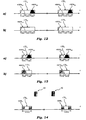
- Figure 12a and 12b show in that respect two embodiments, wherein a 15 MHz band is used simultaneously by either two HSPA carriers or only one HSPA carrier, respectively.
- Figure 13a and 13b shows a spectrum configuration in case of a 10 MHz band with either two HSPA carriers or only one HSPA carrier, respectively.
- the LTE system transmits usually the common channels (e.g. synchronization and broadcast) in the central part of the spectrum using six PRBs centered on the DC subcarrier.
- the inner transition bands of the two HSPA carriers may be sufficient for transmitting these PRBs.
- the proposed mechanism might also be used for operating a LTE system together with narrowband systems such second generation systems (for example GSM, GPRS and EDGE).
- second generation systems for example GSM, GPRS and EDGE.
- Figure 14 shows a possible scenario, where a 10 MHz band is shared with a GSM system having at least one uplink carrier GSM U and at least one downlink carrier GSM D , and which are managed by a GSM base station 50.
- the embodiments shown herein facilitates therefore the gradual re-farming of already licensed frequency bands, which may be switched off progressively and, at the same time, the same spectrum may be used by the LTE system thus maximizing the spectral efficiency achieved by the cellular operator.
Landscapes
- Engineering & Computer Science (AREA)
- Signal Processing (AREA)
- Computer Networks & Wireless Communication (AREA)
- Quality & Reliability (AREA)
- Mobile Radio Communication Systems (AREA)
Claims (12)
- Verfahren zum Übertragen digitaler Signale über einen Kommunikationskanal mit einer gegebenen Bandbreite, wobei das Verfahren Folgendes umfasst:- Übertragen über den Kanal von zumindest einem Signal mit Frequenzspreizung (HSPAU1, HSPAU2, HSPAD1, HSPAD2), wobei das Spektrum des zumindest einen Signals mit Frequenzspreizung (HSPA) abrollende Übergangsbänder (TR) an den Rändern des Spektrums zeigt, und- simultanes Übertragen von zumindest einem Mehrfachträgerübertragungssignal (LTEU, LTED) über zumindest eines der Übergangsbänder (TR), wobei das zumindest eine Mehrfachträgerübertragungssignal (LTEU, LTED) ein orthogonales Frequenzteilungs-Multiplex-Signal (LTEU, LTED) ist,
wobei das Verfahren weiter ein simultanes Übertragen auf zumindest einem der Übergangsbänder (TR) einer Vielzahl von Mehrfachträgerübertragungssignalen (LTEU, LTED) umfasst, und
wobei die Anzahl der Mehrfachträgerübertragungssignale (LTEU, LTED) in der Vielzahl bestimmt wird als eine Funktion von zumindest einem aus den Folgenden:- der Interferenz, die durch die Mehrfachträgerübertragungssignale (LTEU, LTED) bei dem zumindest einen Signal mit Frequenzspreizung (HSPAU1, HSPAU2, HSPAD1, HSPAD2) erzeugt wird,- der Interferenz, die durch das zumindest eine Signal mit Frequenzspreizung (HSPAU1, HSPAU2, HSPAD1, HSPAD2) bei den Mehrfachträgerübertragungssignalen (LTEU, LTED) erzeugt wird, und- der Optimierung des Datendurchsatzes der Mehrfachträgerübertragungssignale (LTEU, LTED) und/oder des zumindest einen Signals mit Frequenzspreizung (HSPAU1, HSPAU2, HSPAD1, HSPAD2). - Verfahren nach Anspruch 1, wobei das zumindest eine Signal mit Frequenzspreizung ein Codeteilungs-Mehrfachzugriffsignal (HSPAU1, HSPAU2, HSPAD1, HSPAD2) ist.
- Verfahren nach einem der Ansprüche 1 oder 2, wobei die spektrale Leistungsdichte des zumindest einen Signals mit Frequenzspreizung (HSPAU1, HSPAU2, HSPAD1, HSPAD2) sich in den Übergangsbändern (TR) von einem Maximalwert zu einem vorbestimmten Minimalwert verringert.
- Verfahren nach Anspruch 1, welches ein Abschätzen der Interferenz, die durch die Mehrfachträgerübertragungssignale (LTEU, LTED) bei dem zumindest einen Signal mit Frequenzspreizung (HSPAU1, HSPAU2, HSPAD1, HSPAD2) erzeugt wird basierend auf einem Kanalqualitätsindikator, der empfangen wird von mehreren Nutzern, die die digitalen Signale über den Kommunikationskanal empfangen, umfasst.
- Verfahren nach einem der vorhergehenden Ansprüche, wobei das zumindest eine Signal mit Frequenzspreizung (HSPAU1, HSPAU2, HSPAD1, HSPAD2) und das zumindest eine Mehrfachträgerübertragungssignal (LTEU, LTED) in synchronisierten Zeitfenstern übertragen wird.
- Verfahren nach Anspruch 5, wobei das Verfahren die folgenden Schritte umfasst:- Übertragen des zumindest einen Signals mit Frequenzspreizung (HSPAU1, HSPAU2, HSPAD1, HSPAD2) während eines ersten Satzes von Zeitfenstern, um das Spektrum zu besetzen,- Deaktivieren der Übertragung des zumindest einen Signals mit Frequenzspreizung (HSPAU1, HSPAU2, HSPAD1, HSPAD2) während eines zweiten Satzes von Zeitfenstern, wodurch das Spektrum freigelassen wird, und- Übertragen während des zweiten Satzes von Zeitfenstern des zumindest einen Multiträgerübertragungssignals (LTEU, LTED) in dem freigelassenen Spektrum durch das zumindest eine Signal mit Frequenzspreizung (HSPAU1, HSPAU2, HSPAD1, HSPAD2).
- Verfahren nach einem der vorhergehenden Ansprüche, weiter umfassend ein Übertragen eines ersten (HSPAU1, HSPAD1) und eines zweiten (HSPAU2, HSPAD2) Signals mit Frequenzspreizung über den Kanal, wobei das erste Signal mit Frequenzspreizung (HSPAU1, HSPAD1) an dem Niederfrequenzrand des Kanals angeordnet ist und das zweite Signal mit Frequenzspreizung (HSPAU2, HSPAD2) an dem oberen Frequenzrand des Kanals angeordnet ist.
- Verfahren nach Anspruch 7, wobei das erste (HSPAU1, HSPAD1) und das zweite (HSPAU2, HSPAD2) Signal mit Frequenzspreizung zusammen ein Paar von inneren Übergangsbändern dazwischen definieren und ein Paar von äußeren Übergangsbändern, die außerhalb von ihnen liegen, definieren, wobei das Verfahren ein Übertragen umfasst:- von zumindest einem Multiträgerübertragungssignal (LTEU, LTED) in zumindest einem der inneren Übergangsbänder (TR);- von zumindest einem Multiträgerübertragungssignal (LTEU, LTED) in zumindest einem der äußeren Übergangsbänder (TR).
- Verfahren nach einem der Ansprüche 7 oder 8, weiter umfassend die Schritte:- Überwachen der Trafiklast des ersten (HSPAU1, HSPAD1) und des zweiten (HSPAU2, HSPAD2) Signals mit Frequenzspreizung,- Deaktivieren der Übertragung von zumindest einem des ersten (HSPAU1, HSPAD1) und des zweiten (HSPAU2, HSPAD2) Signals mit Frequenzspreizung, wenn die angehäufte Trafiklast unterhalb eines vorbestimmten Schwellenwertes fällt, wodurch ein entsprechender Abschnitt des Spektrums freigelassen wird, und- Übertragen von zumindest einem Multiträgerübertragungssignal (LTEU, LTED) in dem Abschnitt des Spektrums, der freigelassen wurde durch das zumindest eine so deaktivierte Signal mit Frequenzspreizung (HSPAU1, HSPAU2, HSPAD1, HSPAD2).
- Übertragungssystem (10, 20, 30, 40) mit:- einer Frequenzspreizungsverarbeitungseinheit (102 bis 120) zum Erzeugen von zumindest einem Basisbandsignal mit Frequenzspreizung,- einer Mehrfachträgerbasisbandübertragungs-Verarbeitungseinheit (202 bis 218) zum Erzeugen von zumindest einem Basisbandsignal für Mehrfachträgerübertragung, wobei das zumindest eine Mehrfachträgerübertragungssignal ein orthogonales Frequenzteilungs-Multiplex-Signal ist;- zumindest einem Funkfrequenz-Frontend (130 bis 136, 230 bis 236, 340 bis 336) zum Konvertieren und Übertragen des zumindest einen Basisbandsignals mit Frequenzspreizung und des zumindest einen Mehrfachträgerübertragungssignals über einen Kommunikationskanal mit einer gegebenen Bandbreite,
wobei das Übertragungssystem (10, 20, 30, 40) ausgebildet ist zum Ausführen der Schritte nach einem der Ansprüche 1 bis 9. - Übertragungssystem nach Anspruch 10, mit:- zumindest einer Überabtasteinheit (130, 230) zum Überabtasten des zumindest einen Basissignals mit Frequenzspreizung und des zumindest einen Mehrfachträgerübertragungssignals, um sie in eine gleiche Abtastfrequenz zu bringen,- einem Kombinierer (340) zum Kombinieren des überabgetasteten Basisbandsignals mit Frequenzspreizung und des überabgetasteten Mehrfachträgerübertragungssignals, und- einem Funkfrequenz-Frontend (332, 334, 336) zum Umwandeln und Übertragen der kombinierten Signale über dem Kommunikationskanal.
- Computerprogrammprodukt, welches in einem Speicher von einem Computer ladbar ist und Softwarecode-Anteile aufweist, die ausgebildet sind, um die Schritte nach einem der Ansprüche 1 bis 9 auszuführen, wenn das Produkt auf einem Computer läuft.
Applications Claiming Priority (1)
| Application Number | Priority Date | Filing Date | Title |
|---|---|---|---|
| PCT/EP2008/008290 WO2010037405A1 (en) | 2008-09-30 | 2008-09-30 | A method of transmitting digital signals, corresponding transmission system, signal and computer program product therefor |
Publications (2)
| Publication Number | Publication Date |
|---|---|
| EP2342880A1 EP2342880A1 (de) | 2011-07-13 |
| EP2342880B1 true EP2342880B1 (de) | 2014-04-02 |
Family
ID=40833604
Family Applications (1)
| Application Number | Title | Priority Date | Filing Date |
|---|---|---|---|
| EP08802716.4A Active EP2342880B1 (de) | 2008-09-30 | 2008-09-30 | Verfahren zum Übertragen von digitalen Signalen, entsprechendes Übertragungssystem und Computerprogrammprodukt dafür |
Country Status (3)
| Country | Link |
|---|---|
| US (1) | US9407400B2 (de) |
| EP (1) | EP2342880B1 (de) |
| WO (1) | WO2010037405A1 (de) |
Families Citing this family (15)
| Publication number | Priority date | Publication date | Assignee | Title |
|---|---|---|---|---|
| JP5260131B2 (ja) * | 2008-04-28 | 2013-08-14 | 株式会社エヌ・ティ・ティ・ドコモ | 基地局、移動局及び共通情報通信方法 |
| US8138541B2 (en) | 2009-07-02 | 2012-03-20 | Micron Technology, Inc. | Memory cells |
| CN102143096B (zh) * | 2010-07-16 | 2013-12-04 | 华为技术有限公司 | 发送物理资源块、及信道估计的方法、基站和用户设备 |
| CN102833196B (zh) * | 2011-06-14 | 2017-02-08 | 中兴通讯股份有限公司 | 一种时分复用滤波方法及装置 |
| CN102412863B (zh) * | 2011-10-17 | 2014-04-16 | 上海交通大学 | 低轨稀路由卫星扩频通信传输方法 |
| KR101888852B1 (ko) * | 2011-12-02 | 2018-09-21 | 삼성전자주식회사 | 휴대용 단말기에서 다이버시티 서비스를 제공하기 위한 장치 및 방법 |
| US8599812B2 (en) * | 2012-03-26 | 2013-12-03 | Qualcomm Incorporated | Encoded wireless data delivery in a WLAN positioning system |
| EP2903198A1 (de) * | 2014-02-04 | 2015-08-05 | Alcatel Lucent | Verfahren und Vorrichtung zum Informationsaustausch |
| EP3205038B1 (de) * | 2014-10-08 | 2020-06-17 | Telefonaktiebolaget LM Ericsson (publ) | Aktivierung von trägern |
| CN107295527B (zh) * | 2016-03-31 | 2019-12-03 | 中国电信股份有限公司 | 同频干扰保护带划分方法、装置及系统 |
| KR102472989B1 (ko) * | 2016-11-30 | 2022-12-01 | 삼성전자주식회사 | 통신 제어 방법 및 전자 장치 |
| US11695507B2 (en) * | 2017-03-24 | 2023-07-04 | Samsung Electronics Co., Ltd. | Apparatus and method for in multiple access in wireless communication |
| EP3763063B1 (de) * | 2018-03-08 | 2021-12-15 | Telefonaktiebolaget Lm Ericsson (Publ) | Verfahren und vorrichtung zur handhabung von antennensignalen zur übertragung zwischen einer basiseinheit und einer entfernten einheit eines basisstationssystems |
| CN112702745A (zh) * | 2019-10-22 | 2021-04-23 | 中兴通讯股份有限公司 | 产生共享载波的方法和装置、处理共享载波的方法和装置 |
| CN115225576B (zh) * | 2022-07-18 | 2023-08-22 | 北京航空航天大学 | 针对航空电子系统中端系统之间的交换式网络流量监测方法 |
Family Cites Families (11)
| Publication number | Priority date | Publication date | Assignee | Title |
|---|---|---|---|---|
| JP3997890B2 (ja) * | 2001-11-13 | 2007-10-24 | 松下電器産業株式会社 | 送信方法及び送信装置 |
| US7280467B2 (en) * | 2003-01-07 | 2007-10-09 | Qualcomm Incorporated | Pilot transmission schemes for wireless multi-carrier communication systems |
| US8149969B2 (en) * | 2005-10-07 | 2012-04-03 | Samsung Electronics Co., Ltd. | Apparatus and method for reduced peak-to-average-power ratio in a wireless network |
| KR100891818B1 (ko) * | 2006-01-27 | 2009-04-07 | 삼성전자주식회사 | 이동통신 시스템에서 복합 다중 접속 장치 및 방법 |
| EP1883258B1 (de) | 2006-07-25 | 2012-08-29 | Alcatel Lucent | Verfahren zur Funkresourcenaufteilung, Computerprogrammprodukt, Funkresourcenverwaltungsmodul und Funkkommunikationsnetz |
| US7649951B2 (en) * | 2006-08-16 | 2010-01-19 | Harris Corporation | System and method for communicating data using symbol-based randomized orthogonal frequency division multiplexing (OFDM) with applied frequency domain spreading |
| EP1924044A1 (de) * | 2006-11-16 | 2008-05-21 | Nokia Siemens Networks Gmbh & Co. Kg | Vorrichtung und Verfahren zum Erzeugen eines Signals um das PAR in einem Mehrträgersystem zu reduzieren |
| KR101631784B1 (ko) * | 2007-01-12 | 2016-06-17 | 텔레폰악티에볼라겟엘엠에릭슨(펍) | 무선 통신 시스템에서의 방법 및 장치 |
| KR101484796B1 (ko) * | 2007-04-23 | 2015-01-20 | 달리 시스템즈 씨오. 엘티디. | N-웨이 도허티 분산형 전력 증폭기 |
| JP5451640B2 (ja) * | 2008-02-11 | 2014-03-26 | テレフオンアクチーボラゲット エル エム エリクソン(パブル) | 通信システムにおけるリンク品質評価方法と装置 |
| US9270413B2 (en) * | 2008-09-02 | 2016-02-23 | Telefonaktiebolaget Lm Ericsson (Publ) | Frequency selective SINR regeneration |
-
2008
- 2008-09-30 EP EP08802716.4A patent/EP2342880B1/de active Active
- 2008-09-30 US US13/121,641 patent/US9407400B2/en active Active
- 2008-09-30 WO PCT/EP2008/008290 patent/WO2010037405A1/en not_active Ceased
Non-Patent Citations (1)
| Title |
|---|
| RAKESH RAJBANSHI: "OFDM-Based Cognitive Radio forDSA Networks", 1 September 2007 (2007-09-01), pages 32 - 33, Retrieved from the Internet <URL:citeseerx.ist.psu.edu/viewdoc/download?doi=10.1.1.69.8554&rep=rep1&type=pdf> [retrieved on 20130125] * |
Also Published As
| Publication number | Publication date |
|---|---|
| EP2342880A1 (de) | 2011-07-13 |
| US20110176532A1 (en) | 2011-07-21 |
| US9407400B2 (en) | 2016-08-02 |
| WO2010037405A1 (en) | 2010-04-08 |
Similar Documents
| Publication | Publication Date | Title |
|---|---|---|
| EP2342880B1 (de) | Verfahren zum Übertragen von digitalen Signalen, entsprechendes Übertragungssystem und Computerprogrammprodukt dafür | |
| CN102318218B (zh) | 用于分布式移动通信的方法、相应的系统和计算机程序产品 | |
| KR101101074B1 (ko) | 서브밴드 스케줄링 및 전력 증폭기 백오프 조절 | |
| US7551546B2 (en) | Dual-mode shared OFDM methods/transmitters, receivers and systems | |
| US8868122B2 (en) | User apparatus, base station apparatus and communication control method | |
| US7792088B2 (en) | Method for partitioning resource space, assigning physical channel, and allocating power in OFDMA-based cellular system | |
| US9065596B2 (en) | Wireless communication system and wireless communication method | |
| Wyglinski | Effects of bit allocation on non-contiguous multicarrier-based cognitive radio transceivers | |
| CN101663849A (zh) | 在移动通信系统中使用的基站装置、用户装置以及方法 | |
| Johansson et al. | Multi-carrier HSPA evolution | |
| EP1931089B1 (de) | Funkkommunikationsgerät und Funkkommunikationsverfahren | |
| CN101690351A (zh) | 随传输功率而定的无线收发机的降低发射 | |
| EP3158824A1 (de) | Verfahren zur reduzierung der fronthaul-last in einem zentralisierten funkzugangsnetzwerk | |
| WO2008118968A1 (en) | System and method for condensed frequency reuse in a wireless communication system | |
| US20240333462A1 (en) | User equipment capability signaling for scheduling to avoid symbol blanking | |
| WO2009133935A1 (ja) | 通信システム、通信装置及び通信方法 | |
| US20100086070A1 (en) | User apparatus, base station apparatus, mobile communication system and communication control method | |
| Iacobucci | Reconfigurable radio systems: network architectures and standards | |
| Priyanto et al. | In-band interference effects on UTRA LTE uplink resource block allocation | |
| Gujral et al. | LTE Evolution towards Carrier Aggregation (LTE-advanced) | |
| US9236975B2 (en) | Mobile subscriber information transmission over multiple uplink frames | |
| Toskala et al. | UTRAN Long‐Term Evolution | |
| AHMED | Performance Evaluation of LTE-Advanced Carrier Aggregation | |
| Dahlman et al. | High data rates in mobile communications | |
| Jiménez et al. | Bit-Loaded H-OFDM Performance in WPAN Environments |
Legal Events
| Date | Code | Title | Description |
|---|---|---|---|
| PUAI | Public reference made under article 153(3) epc to a published international application that has entered the european phase |
Free format text: ORIGINAL CODE: 0009012 |
|
| 17P | Request for examination filed |
Effective date: 20110428 |
|
| AK | Designated contracting states |
Kind code of ref document: A1 Designated state(s): AT BE BG CH CY CZ DE DK EE ES FI FR GB GR HR HU IE IS IT LI LT LU LV MC MT NL NO PL PT RO SE SI SK TR |
|
| AX | Request for extension of the european patent |
Extension state: AL BA MK RS |
|
| 17Q | First examination report despatched |
Effective date: 20110713 |
|
| DAX | Request for extension of the european patent (deleted) | ||
| 17Q | First examination report despatched |
Effective date: 20120220 |
|
| GRAP | Despatch of communication of intention to grant a patent |
Free format text: ORIGINAL CODE: EPIDOSNIGR1 |
|
| INTG | Intention to grant announced |
Effective date: 20131120 |
|
| GRAS | Grant fee paid |
Free format text: ORIGINAL CODE: EPIDOSNIGR3 |
|
| GRAA | (expected) grant |
Free format text: ORIGINAL CODE: 0009210 |
|
| AK | Designated contracting states |
Kind code of ref document: B1 Designated state(s): AT BE BG CH CY CZ DE DK EE ES FI FR GB GR HR HU IE IS IT LI LT LU LV MC MT NL NO PL PT RO SE SI SK TR |
|
| REG | Reference to a national code |
Ref country code: GB Ref legal event code: FG4D |
|
| REG | Reference to a national code |
Ref country code: CH Ref legal event code: EP Ref country code: AT Ref legal event code: REF Ref document number: 660704 Country of ref document: AT Kind code of ref document: T Effective date: 20140415 |
|
| REG | Reference to a national code |
Ref country code: IE Ref legal event code: FG4D |
|
| REG | Reference to a national code |
Ref country code: DE Ref legal event code: R096 Ref document number: 602008031296 Country of ref document: DE Effective date: 20140515 |
|
| REG | Reference to a national code |
Ref country code: AT Ref legal event code: MK05 Ref document number: 660704 Country of ref document: AT Kind code of ref document: T Effective date: 20140402 |
|
| REG | Reference to a national code |
Ref country code: NL Ref legal event code: VDEP Effective date: 20140402 |
|
| REG | Reference to a national code |
Ref country code: LT Ref legal event code: MG4D |
|
| PG25 | Lapsed in a contracting state [announced via postgrant information from national office to epo] |
Ref country code: GR Free format text: LAPSE BECAUSE OF FAILURE TO SUBMIT A TRANSLATION OF THE DESCRIPTION OR TO PAY THE FEE WITHIN THE PRESCRIBED TIME-LIMIT Effective date: 20140703 Ref country code: CY Free format text: LAPSE BECAUSE OF FAILURE TO SUBMIT A TRANSLATION OF THE DESCRIPTION OR TO PAY THE FEE WITHIN THE PRESCRIBED TIME-LIMIT Effective date: 20140402 Ref country code: CZ Free format text: LAPSE BECAUSE OF FAILURE TO SUBMIT A TRANSLATION OF THE DESCRIPTION OR TO PAY THE FEE WITHIN THE PRESCRIBED TIME-LIMIT Effective date: 20140402 Ref country code: FI Free format text: LAPSE BECAUSE OF FAILURE TO SUBMIT A TRANSLATION OF THE DESCRIPTION OR TO PAY THE FEE WITHIN THE PRESCRIBED TIME-LIMIT Effective date: 20140402 Ref country code: BG Free format text: LAPSE BECAUSE OF FAILURE TO SUBMIT A TRANSLATION OF THE DESCRIPTION OR TO PAY THE FEE WITHIN THE PRESCRIBED TIME-LIMIT Effective date: 20140702 Ref country code: NL Free format text: LAPSE BECAUSE OF FAILURE TO SUBMIT A TRANSLATION OF THE DESCRIPTION OR TO PAY THE FEE WITHIN THE PRESCRIBED TIME-LIMIT Effective date: 20140402 Ref country code: NO Free format text: LAPSE BECAUSE OF FAILURE TO SUBMIT A TRANSLATION OF THE DESCRIPTION OR TO PAY THE FEE WITHIN THE PRESCRIBED TIME-LIMIT Effective date: 20140702 Ref country code: IS Free format text: LAPSE BECAUSE OF FAILURE TO SUBMIT A TRANSLATION OF THE DESCRIPTION OR TO PAY THE FEE WITHIN THE PRESCRIBED TIME-LIMIT Effective date: 20140802 Ref country code: LT Free format text: LAPSE BECAUSE OF FAILURE TO SUBMIT A TRANSLATION OF THE DESCRIPTION OR TO PAY THE FEE WITHIN THE PRESCRIBED TIME-LIMIT Effective date: 20140402 |
|
| PG25 | Lapsed in a contracting state [announced via postgrant information from national office to epo] |
Ref country code: HR Free format text: LAPSE BECAUSE OF FAILURE TO SUBMIT A TRANSLATION OF THE DESCRIPTION OR TO PAY THE FEE WITHIN THE PRESCRIBED TIME-LIMIT Effective date: 20140402 Ref country code: SE Free format text: LAPSE BECAUSE OF FAILURE TO SUBMIT A TRANSLATION OF THE DESCRIPTION OR TO PAY THE FEE WITHIN THE PRESCRIBED TIME-LIMIT Effective date: 20140402 Ref country code: AT Free format text: LAPSE BECAUSE OF FAILURE TO SUBMIT A TRANSLATION OF THE DESCRIPTION OR TO PAY THE FEE WITHIN THE PRESCRIBED TIME-LIMIT Effective date: 20140402 Ref country code: LV Free format text: LAPSE BECAUSE OF FAILURE TO SUBMIT A TRANSLATION OF THE DESCRIPTION OR TO PAY THE FEE WITHIN THE PRESCRIBED TIME-LIMIT Effective date: 20140402 Ref country code: PL Free format text: LAPSE BECAUSE OF FAILURE TO SUBMIT A TRANSLATION OF THE DESCRIPTION OR TO PAY THE FEE WITHIN THE PRESCRIBED TIME-LIMIT Effective date: 20140402 Ref country code: ES Free format text: LAPSE BECAUSE OF FAILURE TO SUBMIT A TRANSLATION OF THE DESCRIPTION OR TO PAY THE FEE WITHIN THE PRESCRIBED TIME-LIMIT Effective date: 20140402 |
|
| PG25 | Lapsed in a contracting state [announced via postgrant information from national office to epo] |
Ref country code: PT Free format text: LAPSE BECAUSE OF FAILURE TO SUBMIT A TRANSLATION OF THE DESCRIPTION OR TO PAY THE FEE WITHIN THE PRESCRIBED TIME-LIMIT Effective date: 20140804 |
|
| REG | Reference to a national code |
Ref country code: DE Ref legal event code: R097 Ref document number: 602008031296 Country of ref document: DE |
|
| PG25 | Lapsed in a contracting state [announced via postgrant information from national office to epo] |
Ref country code: RO Free format text: LAPSE BECAUSE OF FAILURE TO SUBMIT A TRANSLATION OF THE DESCRIPTION OR TO PAY THE FEE WITHIN THE PRESCRIBED TIME-LIMIT Effective date: 20140402 Ref country code: DK Free format text: LAPSE BECAUSE OF FAILURE TO SUBMIT A TRANSLATION OF THE DESCRIPTION OR TO PAY THE FEE WITHIN THE PRESCRIBED TIME-LIMIT Effective date: 20140402 Ref country code: SK Free format text: LAPSE BECAUSE OF FAILURE TO SUBMIT A TRANSLATION OF THE DESCRIPTION OR TO PAY THE FEE WITHIN THE PRESCRIBED TIME-LIMIT Effective date: 20140402 Ref country code: EE Free format text: LAPSE BECAUSE OF FAILURE TO SUBMIT A TRANSLATION OF THE DESCRIPTION OR TO PAY THE FEE WITHIN THE PRESCRIBED TIME-LIMIT Effective date: 20140402 Ref country code: BE Free format text: LAPSE BECAUSE OF FAILURE TO SUBMIT A TRANSLATION OF THE DESCRIPTION OR TO PAY THE FEE WITHIN THE PRESCRIBED TIME-LIMIT Effective date: 20140402 |
|
| PLBE | No opposition filed within time limit |
Free format text: ORIGINAL CODE: 0009261 |
|
| STAA | Information on the status of an ep patent application or granted ep patent |
Free format text: STATUS: NO OPPOSITION FILED WITHIN TIME LIMIT |
|
| 26N | No opposition filed |
Effective date: 20150106 |
|
| REG | Reference to a national code |
Ref country code: DE Ref legal event code: R097 Ref document number: 602008031296 Country of ref document: DE Effective date: 20150106 |
|
| PG25 | Lapsed in a contracting state [announced via postgrant information from national office to epo] |
Ref country code: MC Free format text: LAPSE BECAUSE OF FAILURE TO SUBMIT A TRANSLATION OF THE DESCRIPTION OR TO PAY THE FEE WITHIN THE PRESCRIBED TIME-LIMIT Effective date: 20140402 Ref country code: LU Free format text: LAPSE BECAUSE OF FAILURE TO SUBMIT A TRANSLATION OF THE DESCRIPTION OR TO PAY THE FEE WITHIN THE PRESCRIBED TIME-LIMIT Effective date: 20140930 |
|
| REG | Reference to a national code |
Ref country code: CH Ref legal event code: PL |
|
| REG | Reference to a national code |
Ref country code: IE Ref legal event code: MM4A |
|
| PG25 | Lapsed in a contracting state [announced via postgrant information from national office to epo] |
Ref country code: CH Free format text: LAPSE BECAUSE OF NON-PAYMENT OF DUE FEES Effective date: 20140930 Ref country code: SI Free format text: LAPSE BECAUSE OF FAILURE TO SUBMIT A TRANSLATION OF THE DESCRIPTION OR TO PAY THE FEE WITHIN THE PRESCRIBED TIME-LIMIT Effective date: 20140402 Ref country code: LI Free format text: LAPSE BECAUSE OF NON-PAYMENT OF DUE FEES Effective date: 20140930 |
|
| PG25 | Lapsed in a contracting state [announced via postgrant information from national office to epo] |
Ref country code: IE Free format text: LAPSE BECAUSE OF NON-PAYMENT OF DUE FEES Effective date: 20140930 |
|
| PG25 | Lapsed in a contracting state [announced via postgrant information from national office to epo] |
Ref country code: MT Free format text: LAPSE BECAUSE OF FAILURE TO SUBMIT A TRANSLATION OF THE DESCRIPTION OR TO PAY THE FEE WITHIN THE PRESCRIBED TIME-LIMIT Effective date: 20140402 |
|
| PG25 | Lapsed in a contracting state [announced via postgrant information from national office to epo] |
Ref country code: HU Free format text: LAPSE BECAUSE OF FAILURE TO SUBMIT A TRANSLATION OF THE DESCRIPTION OR TO PAY THE FEE WITHIN THE PRESCRIBED TIME-LIMIT; INVALID AB INITIO Effective date: 20080930 Ref country code: TR Free format text: LAPSE BECAUSE OF FAILURE TO SUBMIT A TRANSLATION OF THE DESCRIPTION OR TO PAY THE FEE WITHIN THE PRESCRIBED TIME-LIMIT Effective date: 20140402 |
|
| REG | Reference to a national code |
Ref country code: FR Ref legal event code: PLFP Year of fee payment: 9 |
|
| REG | Reference to a national code |
Ref country code: FR Ref legal event code: PLFP Year of fee payment: 10 |
|
| REG | Reference to a national code |
Ref country code: FR Ref legal event code: PLFP Year of fee payment: 11 |
|
| P01 | Opt-out of the competence of the unified patent court (upc) registered |
Effective date: 20230528 |
|
| P02 | Opt-out of the competence of the unified patent court (upc) changed |
Effective date: 20230602 |
|
| PGFP | Annual fee paid to national office [announced via postgrant information from national office to epo] |
Ref country code: DE Payment date: 20250919 Year of fee payment: 18 |
|
| PGFP | Annual fee paid to national office [announced via postgrant information from national office to epo] |
Ref country code: GB Payment date: 20250923 Year of fee payment: 18 |
|
| PGFP | Annual fee paid to national office [announced via postgrant information from national office to epo] |
Ref country code: FR Payment date: 20250924 Year of fee payment: 18 |
|
| PGFP | Annual fee paid to national office [announced via postgrant information from national office to epo] |
Ref country code: IT Payment date: 20250930 Year of fee payment: 18 |