EP2343251B1 - Dispositif doté d'un élément de rotation, notamment doté d'un rouleau - Google Patents
Dispositif doté d'un élément de rotation, notamment doté d'un rouleau Download PDFInfo
- Publication number
- EP2343251B1 EP2343251B1 EP20100196008 EP10196008A EP2343251B1 EP 2343251 B1 EP2343251 B1 EP 2343251B1 EP 20100196008 EP20100196008 EP 20100196008 EP 10196008 A EP10196008 A EP 10196008A EP 2343251 B1 EP2343251 B1 EP 2343251B1
- Authority
- EP
- European Patent Office
- Prior art keywords
- shaft
- bearing
- roller
- shaft bearing
- section
- Prior art date
- Legal status (The legal status is an assumption and is not a legal conclusion. Google has not performed a legal analysis and makes no representation as to the accuracy of the status listed.)
- Not-in-force
Links
- 238000004140 cleaning Methods 0.000 claims description 7
- 230000008878 coupling Effects 0.000 claims description 6
- 238000010168 coupling process Methods 0.000 claims description 6
- 238000005859 coupling reaction Methods 0.000 claims description 6
- 238000001035 drying Methods 0.000 claims description 2
- 230000005540 biological transmission Effects 0.000 description 17
- 238000009434 installation Methods 0.000 description 7
- 238000012423 maintenance Methods 0.000 description 5
- 238000004519 manufacturing process Methods 0.000 description 4
- 230000002093 peripheral effect Effects 0.000 description 4
- 238000011109 contamination Methods 0.000 description 3
- 239000003973 paint Substances 0.000 description 3
- 239000004952 Polyamide Substances 0.000 description 2
- 238000006073 displacement reaction Methods 0.000 description 2
- 238000010422 painting Methods 0.000 description 2
- 229920002647 polyamide Polymers 0.000 description 2
- 239000004809 Teflon Substances 0.000 description 1
- 229920006362 Teflon® Polymers 0.000 description 1
- 239000000969 carrier Substances 0.000 description 1
- 230000006378 damage Effects 0.000 description 1
- 230000002349 favourable effect Effects 0.000 description 1
- 239000003365 glass fiber Substances 0.000 description 1
- 238000009776 industrial production Methods 0.000 description 1
- 239000002184 metal Substances 0.000 description 1
- 239000003595 mist Substances 0.000 description 1
- 239000007921 spray Substances 0.000 description 1
- 239000000126 substance Substances 0.000 description 1
Images


Classifications
-
- B—PERFORMING OPERATIONS; TRANSPORTING
- B65—CONVEYING; PACKING; STORING; HANDLING THIN OR FILAMENTARY MATERIAL
- B65G—TRANSPORT OR STORAGE DEVICES, e.g. CONVEYORS FOR LOADING OR TIPPING, SHOP CONVEYOR SYSTEMS OR PNEUMATIC TUBE CONVEYORS
- B65G39/00—Rollers, e.g. drive rollers, or arrangements thereof incorporated in roller-ways or other types of mechanical conveyors
- B65G39/10—Arrangements of rollers
- B65G39/12—Arrangements of rollers mounted on framework
-
- B—PERFORMING OPERATIONS; TRANSPORTING
- B65—CONVEYING; PACKING; STORING; HANDLING THIN OR FILAMENTARY MATERIAL
- B65G—TRANSPORT OR STORAGE DEVICES, e.g. CONVEYORS FOR LOADING OR TIPPING, SHOP CONVEYOR SYSTEMS OR PNEUMATIC TUBE CONVEYORS
- B65G13/00—Roller-ways
- B65G13/02—Roller-ways having driven rollers
- B65G13/06—Roller driving means
- B65G13/07—Roller driving means having endless driving elements
-
- F—MECHANICAL ENGINEERING; LIGHTING; HEATING; WEAPONS; BLASTING
- F16—ENGINEERING ELEMENTS AND UNITS; GENERAL MEASURES FOR PRODUCING AND MAINTAINING EFFECTIVE FUNCTIONING OF MACHINES OR INSTALLATIONS; THERMAL INSULATION IN GENERAL
- F16C—SHAFTS; FLEXIBLE SHAFTS; ELEMENTS OR CRANKSHAFT MECHANISMS; ROTARY BODIES OTHER THAN GEARING ELEMENTS; BEARINGS
- F16C13/00—Rolls, drums, discs, or the like; Bearings or mountings therefor
- F16C13/02—Bearings
-
- F—MECHANICAL ENGINEERING; LIGHTING; HEATING; WEAPONS; BLASTING
- F16—ENGINEERING ELEMENTS AND UNITS; GENERAL MEASURES FOR PRODUCING AND MAINTAINING EFFECTIVE FUNCTIONING OF MACHINES OR INSTALLATIONS; THERMAL INSULATION IN GENERAL
- F16C—SHAFTS; FLEXIBLE SHAFTS; ELEMENTS OR CRANKSHAFT MECHANISMS; ROTARY BODIES OTHER THAN GEARING ELEMENTS; BEARINGS
- F16C19/00—Bearings with rolling contact, for exclusively rotary movement
- F16C19/02—Bearings with rolling contact, for exclusively rotary movement with bearing balls essentially of the same size in one or more circular rows
- F16C19/04—Bearings with rolling contact, for exclusively rotary movement with bearing balls essentially of the same size in one or more circular rows for radial load mainly
Definitions
- the invention relates to a device, in particular a conveying device, with at least one rotation element, in particular with a rotating element designed as a roller, and with a rotatable shaft carrying the rotating element, which is received with a first bearing portion in a first shaft bearing and with a second shaft bearing is held in a second shaft bearing, wherein the first bearing portion of the shafts in the first shaft bearing is displaceable such that the second bearing portion is released from the second shaft bearing.
- Such a device is known from GB 796,061 A and the US 1,919,495 A known.
- Such devices are used in industrial production plants, in particular in painting or cleaning systems. With them can z.
- the baskets, frames or scaffolding are shifted here on rotation elements in the form of roles.
- These rollers are often exposed to high mechanical loads as well as dirt and wear. It is therefore necessary that the rolls are cleaned from time to time, be repaired and replaced. In order for the rolls to be replaced and installed, a production plant must be shut down.
- the object of the invention is to provide a device, in particular a conveyor, which allow a quick and easy replacement in case of contamination or wear.
- the first bearing section of the shaft can be displaced in the first shaft bearing in such a way that the second bearing section accommodated in the second shaft bearing is released.
- provision can be made, in particular, for the first bearing section of the shaft to be displaceable in the direction of the axis of the shaft.
- this axis can be an axis of rotation for the shaft.
- this pivot axis is oriented perpendicular to the axis of the shaft, in particular perpendicular to a rotation axis of the shaft.
- the shaft with its first bearing portion can be pulled out of the first shaft bearing.
- the shaft can be designed to be rotationally movable or else stationary.
- the invention is based on the idea to provide for a shaft with rotary elements in a conveyor a tension lock, by means of which the shaft is held in its first shaft bearing and in its second shaft bearing by itself.
- the device comprises a spring means which acts on the shaft with a force acting preferably in the direction of the axis of rotation of the shaft.
- the spring means serves to securely hold the bearing portion of the shaft in the second shaft bearing.
- the tension lock may be opened by applying to the shaft a force having a force component parallel to the axis of the shaft facing the first shaft bearing.
- An idea of the invention is also to rotatably support the first shaft bearing of the shaft. It is advantageous to provide for the coupling of a rotational movement of the shaft and the first shaft bearing, a rotation transmission means. Then, a drive of the shaft and the rotational elements received thereon is possible with a rotary drive acting on the first shaft bearing. Because the shaft can be moved on the second shaft bearing, when the quick-release closure is opened, then no gear parts of the rotary drive must be disassembled for removal of the shaft. Also, the second shaft bearing is preferably rotatable. The rotation elements on a shaft can be arranged rotationally fixed or rotatably mounted.
- a finding of the invention is in particular that with a rotary element in the form of a roller having one or more longitudinal grooves, high frictional forces can be transmitted to transport objects in a conveyor device. In order to ensure consistent frictional forces over a long period of time, it is favorable for cleaning to provide these rollers in the conveyor a Rollenabstreifer.
- a rotary element in a device can be embodied with a rotary body surrounded by the shaft in a section which can be dismantled into a part and into a second part and which rests on the shaft only with a circumferential segment.
- a rotating element can be fixed to a shaft in a conveying device by only applying parts of a rotating body of the rotating element to the shaft and then subsequently connecting them. This can be avoided in particular that the rotation element must be pushed onto the shaft during installation over a front end of the shaft. This allows the installation and removal of rotating elements in the conveyor, without disassembly of waves is required, which hold the rotation elements.
- a particularly high mechanical strength of rotating elements is ensured by the rotation elements are made in polyamide, which is glass fiber reinforced. In a chemically aggressive environment, rotational elements that consist of Teflon are advantageous. With rotating elements made of metal, high lifetimes can be achieved.
- a rotation element in a device according to the invention can, for. B. be designed as a role. But it is also possible to perform a rotation element as a gear.
- the first part and the second part of the reel body are connected in a connecting section by means of a positive locking, which blocks a relative movement of the first and the second part perpendicular to an axis of the shaft and which causes a relative movement of the first and the second part in the direction of the axis Shaft releases the parts can be connected and released by moving along the shaft. This allows rapid assembly and disassembly of rotary elements on shafts, which are installed in a conveyor.
- connection of the first and second parts by means of positive locking, in which a portion of the first part z.
- a toothed element engages in a receptacle formed on the second part or engage in the portions of the first and the second part in a third element.
- a connection of the parts also be effected with screws.
- the rotation elements may also be formed with two or more longitudinally displaced form-fitting sections. The rotation elements can be pressed in particular by means of a spring means against a stop, in order to transmit in this way a rotational movement of the shaft on the roller.
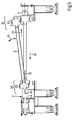
- the conveyor device 1 is a so-called roller conveyor, on which a skid 3 with runners 4 can be moved.
- the conveyor device 1 is designed for use in the spray booth of a paint shop for motor vehicle bodies. But it is also suitable for moving bodies through other areas of a paint shop, in which the conveyor 1 can be contaminated by paint mist, cleaning substances or Spangut and in which the cleaning of the conveyor 1 should be avoided by means of high-pressure cleaner or is not readily possible.
- the conveying device 1 has rollers 25, 27 formed as rotational elements, which are mounted on shafts 5. On each shaft 5, two rollers are arranged: a support roller 25 and a guide roller 27, which serves to guide the runner 4 of the skid 3.
- Each shaft 5 is held in a first shaft bearing 7 and in a second shaft bearing 11.
- the shaft bearings 7 are accommodated on a first carrier 9.
- the shaft bearings 11 are located on a carrier 13.
- the shafts 5 are coupled via a toothed belt transmission 21, which is associated with a drive in the form of an electric motor. Instead of the belt drive, a chain transmission can be provided.
- the supports 9, 13 rest on supports 15, 17. These supports are fixed on a base 19 with foundation.
- a skid 3 with skids 4 can be moved in accordance with the double arrow 29 due to a frictional force transmitted via the rollers 25, 27.
- the conveyor device 1 comprises removable cover plates 10, 12, 14 for the toothed belt transmission 21, for the shaft bearings 7, 11 of the shaft 5, for the rollers 25, 27 and for the skids 4 of the skid third
- the Fig. 2 shows a section of the conveyor device 1 with a shaft 5.
- the shaft 5 is received in the first shaft bearing 7 with a bearing portion 29, on which the support roller 25 is located.
- the bearing portion 29 is fixed by means of a releasable spring tension lock 32 in a connecting piece 34 on the shaft 5.
- the shaft bearing 7 in turn is non-rotatably connected to the transmission shaft 33 of the toothed belt transmission 21.
- With a bearing portion 35 the shaft 5 is mounted in the second shaft bearing 11.
- the guide roller 27 is formed.
- According to the bearing portion 29 and the bearing portion 35 is fixed by means of a releasable spring tensioner 36 in a fitting 38 on the shaft 5 rotatably.
- the second shaft bearing 11 is held in a pivot bearing 39 on the carrier 13.
- the Fig. 3 shows the marked with the circle III area of the section in the conveyor device 1 from Fig. 2 in an enlarged view.
- the cover plates 10 form a housing for the toothed belt transmission 21.
- the transmission shaft 33 On the side facing the shaft bearing 7, the transmission shaft 33 has a centrifugal disc 34.
- the housing formed by the cover plates at bushings for the transmission shafts 33 of the toothed belt transmission 21 is sealed. In the housing so that the toothed belt transmission 21 is encapsulated. The toothed belt transmission 21 of the conveyor device 1 is thus secured against contamination.
- the shaft bearing 7 comprises a joint bush 41.
- a spring means designed as a helical spring 43 is arranged in this joint bush 41.
- the coil spring 43 is received with an end facing the transmission shaft 33 in a rear portion of the hinge bush 41 and supported there.
- An end of the helical spring 43 pointing toward the transmission shaft 33 acts on the bearing section 29 of the shaft 5.
- the bearing section 29 of the shaft 5 comprises a joint body 45.
- the joint body 45 has a joint surface 46 and has a joint axis 47.
- the hinge axis 47 is perpendicular to the axis 42 of the shaft 5.
- the hinge surface 46 has a constant radius of curvature r.
- In the hinge axis 47 of the joint body 45 is a through hole 48. In this bore 48 hinge pin 49 is arranged.
- the hinge pin 49 has two ends that protrude from the joint body. These ends engage in two slot-shaped grooves 51 which are formed on the hinge bushing 41. The hinge pin 49 is guided in these slot-shaped grooves 51 on the joint bushing 41.
- the hinge pin 49 has a double function. The hinge pin 49 causes a rotational coupling of the shaft 5 with the hinge bushing 41 about the axis 42 of the shaft 5.
- the hinge pin 49 also acts as a propeller shaft, which is displaced according to the double arrow 53. By means of the hinge pin 49, the shaft 5 is pivotally guided with its bearing portion 29 in the shaft bearing 7.
- the Fig. 4 shows the marked with the circle IV area of the section of the conveyor device 1 from Fig. 2 in an enlarged view.
- a joint body 55 is formed, which corresponds to the joint body 45 in the bearing portion 29.
- the second bearing portion 39 is guided by means of a bolt 57 in two slot-shaped grooves 59 to the second shaft bearing 11.
- the second shaft bearing 11 is received in the pivot bearing 39 with a shaft 59.
- the pivot bearing 39 is fixed to the carrier 13.
- the force acting on the bearing portion 29 of the shaft 5 coil spring 43 holds the second bearing portion 35 of the shaft 5 in the second shaft bearing eleventh
- 27 are formed in the peripheral surfaces of the rollers 25, extending in the circumferential direction groove-shaped depressions 63, 65. These depressions 63, 65 run where the skid 3 rests, parallel to the runners 4 of the skid 3. The depressions 63, 65 cause a locally increased pressure between the runners 4 of the skid 3 and the rollers 25, 27.
- the carrying rollers 25, 27 are cleaned by means of grooved scrapers 67, 69, which are attached in a pivotable manner to the first carrier 9 and the second carrier 13, respectively.
- the Nutenabstreifer 67, 69 have teeth 68, 70, which engage in the recesses 63, 65 of the rollers 25, 27.
- the arrangement and design of the shaft bearings 7, 11, and the bearing portions 29, 35 of the shafts 5 in the conveyor device 1 allows rapid removal and installation of shafts and rollers in the context of assembly and maintenance work: For this purpose, the Nutenabstreifer 67, 69th from its engaged position with the groove-shaped recesses 63, 65 of the rollers 25, 27 pivoted. Then the cover plates 14 for the runners 4 of the skids 3 are removed where the removal or installation of a shaft 5 should take place.
- the Fig. 5 is a section of a portion of the conveyor 1, in which the cover plates 12, 14 are removed.
- a shaft 5 with the rollers 25, 27 is very accessible here for a maintenance force.
- the shaft 5 can then be brought to a workshop for overhaul and cleaning with the rollers 25, 27.
- the installation of a shaft 5 can be carried out in a corresponding manner to the removal: First, the bearing portion 29 of the shaft 5 is inserted into a hinge bushing 41 on the conveyor device 1. In this case, the hinge pin 49 is brought into engagement with the grooves 51 in the joint bushing 41. The maintenance force must then move the bearing portion 29 against the force of the coil spring 43 in the hinge bush 41. Then, the shaft 5 is pivoted in the rotation axis 42 of the shaft 5. With the assistance of the force of the coil spring 43, the shaft 5 can then be introduced into the shaft bearing 11 with the bearing section 35.
- the Fig. 6 shows a conveyor 101 in the form of a roller conveyor, which is designed for moving shopping carts 103 or transport crates through a production facility.
- the conveyor 101 includes a plurality of shafts 105, 107. Each shaft 105, 107 is received in a shaft bearing 109, which is located on the carrier 111, and held in a shaft bearing 113, which is arranged on the carrier 115.
- the carriers 111, 115 are like the carrier of the conveyor 1 from Fig. 1 mounted on supports 117 and 119.
- the shafts 105 are coupled via a toothed belt transmission 121. They can be driven by means of an electric motor 123.
- the waves 107, however, no drive is assigned.
- Wheels 105, 127 and 129 are received on the shafts 105.
- the rollers 125, 127 and 129 are rotatably connected to the shafts 105.
- the waves 107 on the other hand carry rollers 131, 133 and 135, which are rotatably mounted.
- the rollers 125, 127 and 129 and 131, 133 and 135 in the conveyor are made of polyamide.
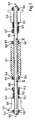
- the Fig. 7 is a partial section of a shaft 105 in the conveyor 101.
- the shaft 105 has an axis of rotation 102.
- the roller 125 has an end face 137 into which a to the end face 137 facing connecting portion of a ring member 139 engages.
- the ring element 139 is secured against rotation on the shaft 105 by means of a fastening screw 141.
- the roller 125 is pressed against the ring element 139 by means of a spring element 145 acting on the end face 143 of the roller 125.
- the spring element 145 acts on an annular disc 147 which rests against the end face 143 of the roller 125.
- the spring element 145 is supported by a ring element 149 which is secured on the shaft 105 by means of a fastening screw 151.
- the roller 127 is a roller. It extends in the longitudinal direction of the shaft 105. At the end face 153 of the roller 127 engages a connection portion of a ring member 155 a.
- the ring element 155 is secured against rotation on the shaft 105 by means of a fastening screw 157.
- the roller 127 is additionally secured with a voltage applied to the end face 159 ring member 161 against lateral displacement.
- the ring element 161 is fixed on the shaft 105 by means of a fastening screw 163.
- the roller 129 is received according to the roller 125 on the shaft 105. It is rotatably coupled by means of two ring elements 165, 167, a spring element 169 and an annular disc 171 with the shaft 105.
- the rollers 125, 127 and 129 are designed so that they can be mounted on the shaft 105, without an expansion of the shaft 105 from the shaft bearings 111, 113 is required. The same applies to the rollers 131, 133 and 135 and the shafts 106 of the conveyor 101.
- the Fig. 8 shows a portion of the shaft 105 with the roller 125.
- the roller 125 has a roller body comprising a first part 173 and a second part 175.
- the first part 173 and the second part 175 of the roller 125 are detachably connected.
- the first part 173 has a positive engagement portion which is in mesh with a positive engagement portion formed in the second part 175.
- the first and second parts 173, 175 of the roller 125 are applied to the shaft 105.
- the movement of the parts 173, 175 is coupled about the axis 177 of the shaft 105.
- a possible lateral displacement parts 173, 175 of the roller 125 is prevented by the ring elements 139, 149, the spring element 145 and the washer 147 on the shaft 105.
- the Fig. 9 shows the roller 125 in a disassembled state.
- the first part 173 of the roller 125 has the geometry of a half-cylinder.
- the contour of the inner wall 179 of the half-cylinder is formed according to the radius r of the shaft 105.
- the part 173 has a first planar lateral surface 180 and a second planar lateral surface 181.
- these lateral surfaces 181 extend along the shaft.
- This part 173 of the roller 125 and the part 175 of the roller 125 are in this case only with the peripheral segment 182 or the peripheral segment 184 to the roller 105.
- a toothing element 183 is formed on the lateral surface 180.
- the toothed element 183 is arcuately curved and projects obliquely out of the first lateral surface 179.
- the lateral surface 181 has a toothing element 185 corresponding to the toothed element 183.
- the toothed elements 183, 185 point towards the outer peripheral surface thereof.
- the lateral surface 180 and 181 with the gear elements 183, 185 act as a form-fitting portion 187 of the part 173 of the roller 125th
- the second part 175 of the roller 125 is also shaped as a half-cylinder.
- the outer surface 175 has a first planar lateral surface 189 and a second planar lateral surface 191.
- the lateral surfaces 189, 191 each have a slot-shaped receptacle 193, 195 for the toothed element 183 or the toothed element 185.
- the lateral surfaces 189, 191 with the slot-shaped receptacles 193, 195 form a form-fitting portion 197 for the second part 175 of the roller 125.
- This engagement can be effected by first placing the part 173 in a first step and placing the part 175 on the shaft 105. In a subsequent second step, then the part 173 and the part 175 along the axis of the shaft 105 can be pushed over each other. In this case, get the part 173 and the part 175 at their form-fitting sections in mutual engagement.
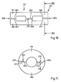
- the Fig. 10 shows a section of the roller 127 Fig. 7 ,
- the roller 127 has a first roller part 197 and a second roller part 199.
- the roller parts 197, 199 each have the shape of a cylinder half.
- the first and the second roller part 197, 199 are connected to three in the longitudinal direction of the shaft 105 staggered sections 200, 202 and 204 positive locking.
- the roller parts 197, 199 each have three positive-locking sections 201, 203, 205 and 207, 209 and 211.
- the Fig. 11 is a section of the roller 127 along the line XI - XI in Fig. 10 ,
- the form-fitting section 205 of the roller part 197 has a connection surface 206 with a dovetail coupling element 215.
- the form-fitting section 205 also has a connection surface 219 a receptacle 221 for a dovetail coupling element 223, which is arranged on a connection surface 225 of the roller part 199.
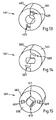
- FIGS. 13, 14 and 15 are shown further examples of rotary elements in the form of rollers with a collapsible body of revolution, which is composed of several parts. These rotation elements can be mounted on a shaft, without the rotation elements for this must be pushed over a front end of the shaft.
- the roll 301 in Fig. 12a has a roller part 303 and a roller part 305.
- the Fig. 12b shows the roller 301 in a section.
- the reel part 303 is connected to the reel part 305 via a disk 307 arranged on the shaft, which is fixed by screws 309, 311 in the reel parts 303 and 305.
- the roll 401 in Fig. 13 has roller parts 403, 405, the connection sections have, in which form-fitting elements 407, 409 are formed with hook geometry.
- roller 501 In the Fig. 14 a roller 501 is shown, the roller parts 503, 505 having connection elements 507, 509 which are curved in a circular arc.
- the roller 501 is designed for connection to a square profile shaft.
- the Fig. 15 shows a roller 601 with roller parts 603, 605, which are connected by means of two rails 607, 609.
- the rails 607, 609 have a dovetail-shaped cross-section.
- the roller members 603 and 605 have a recess 611, 613.
- the recesses 611, 613 serve to engage a toothed member disposed on the shaft. As a result, a torque transmission from the shaft to the roller 601 is made possible.
- rollers can be removed from a shaft in particular by destroying the roller by means of a chisel or a sawing tool. The removed by destruction of roles can then be replaced by the described roles with a multi-part reel body, without the need for an expansion of the shaft in a conveyor is necessary.
Landscapes
- Engineering & Computer Science (AREA)
- Mechanical Engineering (AREA)
- General Engineering & Computer Science (AREA)
- Rollers For Roller Conveyors For Transfer (AREA)
- Rolls And Other Rotary Bodies (AREA)
- Coating Apparatus (AREA)
Claims (15)
- Dispositif, en particulier dispositif de transport (1), présentant au moins un élément rotatif (25, 27) et un arbre (5) apte à se déplacer en rotation et portant l'élément rotatif (25, 27), l'arbre étant repris dans un premier palier d'arbre (7) par une première partie de palier (29) et maintenu dans un deuxième palier d'arbre (11) par une deuxième partie de palier (35),
la première partie de palier (29) de l'arbre (5) pouvant être déplacée dans le premier palier d'arbre (7) de telle sorte que la deuxième partie de palier (35) soit libérée du deuxième palier d'arbre (11), caractérisé en ce que
la première partie de palier (29) de l'arbre (5) comporte un corps d'articulation (45) et le premier palier d'arbre (7) présente une douille d'articulation (41) qui reprend le corps d'articulation (45) et qui est accouplée à rotation à l'arbre (5), l'arbre (5) étant guidé à pivotement avec le corps d'articulation (45) dans la douille d'articulation (41) de telle sorte que l'arbre (5) puisse pivoter avec le corps d'articulation (45) dans le premier palier d'arbre (7) autour d'un axe (47) perpendiculaire à l'axe (42) de l'arbre (5) lorsque la deuxième partie de palier (35) est libérée et puisse ainsi être extrait hors du premier palier d'arbre (7) avec la première partie de palier (29). - Dispositif selon la revendication 1, caractérisé en ce que le corps d'articulation (45) comporte un goujon d'articulation (49) qui guide à pivotement l'arbre (5) dans la douille d'articulation.
- Dispositif selon la revendication 2, caractérisé en ce que le goujon d'articulation (49) a pour effet un accouplement rotatif de l'arbre (5) sur la douille d'articulation (41).
- Dispositif selon la revendication 3, caractérisé en ce que la douille d'articulation (41) présente deux rainures (51) en forme de fente destinées à engager le goujon d'articulation (49), le goujon d'articulation (49) présentant deux extrémités qui débordent du corps d'articulation (45) et qui s'engagent dans les rainures (51).
- Dispositif selon l'une des revendications 1 à 4, caractérisé en ce que le corps d'articulation (45) présente une surface d'articulation (46) dont le rayon de courbure (r) est constant.
- Dispositif selon l'une des revendications 1 à 5, caractérisé en ce qu'il présente un moyen élastique (43) qui applique sur l'arbre (5) une force qui maintient la deuxième partie de palier (35) dans le deuxième palier d'arbre (11).
- Dispositif selon l'une des revendications 1 à 6, caractérisé en ce que le premier palier d'arbre (7) est monté à rotation.
- Dispositif selon la revendication 7, caractérisé en ce que le premier palier d'arbre (7) est accouplé à un entraînement en rotation (21, 23).
- Dispositif selon l'une des revendications 1 à 8, caractérisé en ce que le deuxième palier d'arbre (11) est monté à rotation.
- Dispositif selon l'une des revendications 1 à 9, caractérisé en ce que l'élément de rotation (125, 127, 129, 131, 133, 135, 301, 401, 501, 601) présente un corps de rotation qui entoure l'arbre (105, 106), qui peut être décomposé en au moins une première partie (173) et une deuxième partie (175) et qui repose sur l'arbre (105, 106) uniquement par un segment périphérique (182, 184).
- Dispositif selon la revendication 10, caractérisé en ce que la première partie (173) et la deuxième partie (175) sont reliées en une section (187, 197) au moyen d'une liaison en correspondance géométrique qui bloque le déplacement de la première partie (173) et de la deuxième partie (175) perpendiculairement à un axe (102) de l'arbre (105) et qui libère le déplacement de la première partie (173) et de la deuxième partie (175) dans la direction de l'axe (102) de l'arbre (105).
- Dispositif selon la revendication 11, caractérisé en ce que la correspondance géométrique est formée par un élément denté (183, 185) disposé sur la première partie (173) et qui s'engage dans un logement (193, 195) formé sur la deuxième partie (175), ou la liaison en correspondance géométrique est formée par un élément de fixation (301, 311).
- Dispositif selon les revendications 12 ou 13, caractérisé en ce que deux ou plusieurs segments de liaison par correspondance géométrique (200, 202, 204) décalés les uns des autres dans le sens de la longueur sont prévus pour assurer la liaison en correspondance géométrique d'une première partie (197) et d'une deuxième partie (199) du corps de rotation.
- Dispositif selon les revendications 1 à 13, caractérisé en ce que l'élément de rotation (125) est repoussé contre une butée (139) par un moyen élastique (145) et en ce que la butée (139) transfère à l'élément de rotation (125) un déplacement de rotation de l'arbre (105).
- Installation industrielle de séchage, de nettoyage et/ou de peinture dotée d'un dispositif selon l'une des revendications 1 à 14 comme dispositif de transport (1) assurant le déplacement de carrosseries de véhicules.
Applications Claiming Priority (1)
| Application Number | Priority Date | Filing Date | Title |
|---|---|---|---|
| DE201010000803 DE102010000803A1 (de) | 2010-01-12 | 2010-01-12 | Vorrichtung mit Rotationselement, insbesondere mit Rolle |
Publications (3)
| Publication Number | Publication Date |
|---|---|
| EP2343251A2 EP2343251A2 (fr) | 2011-07-13 |
| EP2343251A3 EP2343251A3 (fr) | 2011-08-17 |
| EP2343251B1 true EP2343251B1 (fr) | 2012-09-26 |
Family
ID=43856061
Family Applications (1)
| Application Number | Title | Priority Date | Filing Date |
|---|---|---|---|
| EP20100196008 Not-in-force EP2343251B1 (fr) | 2010-01-12 | 2010-12-20 | Dispositif doté d'un élément de rotation, notamment doté d'un rouleau |
Country Status (3)
| Country | Link |
|---|---|
| EP (1) | EP2343251B1 (fr) |
| CN (1) | CN102126608B (fr) |
| DE (1) | DE102010000803A1 (fr) |
Families Citing this family (2)
| Publication number | Priority date | Publication date | Assignee | Title |
|---|---|---|---|---|
| DE102020205250B4 (de) * | 2020-04-24 | 2021-11-11 | Kocks Technik Gmbh & Co Kg | Führungsvorrichtung für Langprodukte |
| IT202000024745A1 (it) * | 2020-10-20 | 2022-04-20 | Rulli Rulmeca S P A | Rullo, trasportatore a rulli, pluralità di trasportatori a rulli, metodo di manutenzione di rullo, metodo di gestione di un trasportatore a rulli, metodo di gestione di una pluralità di trasportatori a rulli |
Family Cites Families (33)
| Publication number | Priority date | Publication date | Assignee | Title |
|---|---|---|---|---|
| US1644611A (en) * | 1925-02-28 | 1927-10-04 | H Dux Company Inc Dr | Ball bearing |
| US1758280A (en) * | 1929-05-17 | 1930-05-13 | David T Evans | Roller for traveling conveyers |
| US1919495A (en) * | 1930-12-05 | 1933-07-25 | Lamson Co | Conveyer |
| GB445445A (en) * | 1934-10-31 | 1936-04-09 | Emile Piquerez | An improved roller conveyer |
| US2033074A (en) * | 1934-11-30 | 1936-03-03 | Bantam Ball Bearing Company | Antifriction bearing |
| GB796061A (en) * | 1955-04-02 | 1958-06-04 | John Kerr & Company Manchester | Improvements in or relating to roller-way conveyors |
| US3140130A (en) * | 1961-08-09 | 1964-07-07 | Roller Bearing Co Of America | Keyed segmented race rings and improved method of making same |
| US3343893A (en) * | 1965-01-27 | 1967-09-26 | Ingersoll Rand Co | Floating bearing of split-shell construction |
| FR2085199B1 (fr) * | 1970-01-23 | 1973-12-21 | Merenda Adrien Et Cie | |
| DE2324256A1 (de) * | 1973-05-14 | 1974-12-05 | Interroll Foerdertechnik Gmbh | Rollen fuer rollenbahnen |
| JPS54143581U (fr) * | 1978-03-27 | 1979-10-05 | ||
| EP0013628A1 (fr) * | 1979-01-15 | 1980-07-23 | The Torrington Company | Palier à rouleaux |
| US4311226A (en) * | 1980-01-28 | 1982-01-19 | Gifford-Hill & Company, Inc. | Trapped-axle conveyor roll |
| GB2095193B (en) * | 1981-03-10 | 1984-12-05 | Handling Design & Construction | Mounting rollers on rollerways |
| US4402390A (en) * | 1981-06-12 | 1983-09-06 | Stilson Division Of Stocker & Yale, Inc. | Conveyor roll |
| US4416650A (en) * | 1981-06-26 | 1983-11-22 | The E.W. Buschman Company | Drive wheel and sprocket assembly |
| US4421224A (en) * | 1981-11-30 | 1983-12-20 | Dingman Robert D | Driven roller for accumulator conveyor |
| SE437971B (sv) * | 1983-03-16 | 1985-03-25 | Cavotec Ab | Pa en trumma verkande bromsanordning |
| JPS6138673U (ja) * | 1984-08-14 | 1986-03-11 | コニカ株式会社 | 画像形成定着装置 |
| IT8423457V0 (it) * | 1984-10-05 | 1984-10-05 | Siat Spa | Disposizione di montaggio di rulli, in trasportatori a rulli e rulliere in genere. |
| DE8634166U1 (de) * | 1986-12-20 | 1987-07-23 | Kunststofftechnik Rodenberg GmbH & Co KG, 3054 Rodenberg | Stützrolle, insbesondere für Förderbänder od. dgl. |
| US5117970A (en) * | 1991-06-19 | 1992-06-02 | Asgco Manufacturing, Inc. | Idler roller sleeve |
| US5346438A (en) * | 1992-08-18 | 1994-09-13 | R. G. Technical Associates, Inc. | Belt guide pulley |
| US5678676A (en) * | 1995-01-20 | 1997-10-21 | Hk Systems, Inc. | Roller shaft mounting for sound and motion control |
| DE19641317A1 (de) * | 1996-10-08 | 1998-04-16 | Bleichert Foerderanlagen Gmbh | Rollenbahn und Tragrolle dafür |
| US6910571B1 (en) * | 2003-05-15 | 2005-06-28 | Dorner Mfg. Corp. | Multi-section conveyor drive roller |
| AU2004265203A1 (en) * | 2003-08-18 | 2005-02-24 | Fps Food Processing Systems B.V. | Apparatus for weighing and conveying objects |
| CN2657344Y (zh) * | 2003-09-27 | 2004-11-17 | 鸿富锦精密工业(深圳)有限公司 | 铰接机构 |
| DE102005055731B4 (de) * | 2005-11-23 | 2020-01-02 | Volkswagen Ag | Tragrollenanordnung und Transporteinrichtung |
| US20070261933A1 (en) * | 2006-04-26 | 2007-11-15 | Scott C W | Conveyor roller assembly and conveyor roller insert |
| ES2382451T3 (es) * | 2006-11-07 | 2012-06-08 | Transmisiones Mecánicas Ave, S.A. | Rodillo de soporte |
| DE202006017757U1 (de) * | 2006-11-22 | 2007-01-11 | Maschinenfabrik Ravenstein Gmbh | Seitenwange und damit ausgestattete Rollenbahn |
| DE102007044507A1 (de) * | 2007-09-18 | 2009-03-19 | Heinrich Kittner | Ring, teilbar, zum Antrieb beweglicher technischer Anlagen |
-
2010
- 2010-01-12 DE DE201010000803 patent/DE102010000803A1/de not_active Withdrawn
- 2010-12-20 EP EP20100196008 patent/EP2343251B1/fr not_active Not-in-force
-
2011
- 2011-01-12 CN CN201110005116.0A patent/CN102126608B/zh not_active Expired - Fee Related
Also Published As
| Publication number | Publication date |
|---|---|
| CN102126608B (zh) | 2015-10-28 |
| CN102126608A (zh) | 2011-07-20 |
| DE102010000803A1 (de) | 2011-07-14 |
| EP2343251A3 (fr) | 2011-08-17 |
| EP2343251A2 (fr) | 2011-07-13 |
Similar Documents
| Publication | Publication Date | Title |
|---|---|---|
| EP2163495B1 (fr) | Transporteur à rouleaux avec module d'arbres à entraînement | |
| DE2822686C2 (fr) | ||
| DE102012104213B4 (de) | Transportsystem für Behandlungsmaschinen sowie Behandlungsmaschine | |
| EP2163496B1 (fr) | Transporteur à rouleaux avec module d'entraînement séparé | |
| EP2837545A2 (fr) | Unité de transport et système de transport doté de telles unités de transport | |
| DE102011018943A1 (de) | Transportstrecke für Behandlungsmaschinen sowie Behandlungsmaschine | |
| EP0149694A1 (fr) | Convoyeur à rouleaux à friction | |
| WO2017076787A1 (fr) | Haveuse-chargeuse à tambour | |
| DE102009036503A1 (de) | Spannvorrichtung für Rotationseinheiten in Reinigungskammer bzw. Reinigungsmaschine | |
| EP2343251B1 (fr) | Dispositif doté d'un élément de rotation, notamment doté d'un rouleau | |
| EP3390250B1 (fr) | Rouleau de roulement, mécanisme à rouleau de roulement, chaîne à maillons et utilisation d'une chaîne à maillons comme chaîne de transport | |
| DE3017942C2 (de) | Friktionsrollenbahn | |
| EP1572386B1 (fr) | Laminoir comprenant des moyens pour le changement des cylindres | |
| EP3388200A1 (fr) | Dispositif de remise en état de chaînes | |
| DE10062084A1 (de) | Tragrolle für eine Rollenbahn | |
| EP1572495A1 (fr) | Vehicule d'aire de stationnement pourvu d'un dispositif d'entrainement a vis sans fin | |
| DE3624482A1 (de) | Vorrichtung fuer den vorschub von zu beschichtenden bauteilen | |
| DE3943051A1 (de) | Angetriebener rollenbahnfoerderer | |
| DE3907730C2 (fr) | ||
| WO2001047791A1 (fr) | Convoyeur a rouleaux servant a transporter et a positionner des articles a transporter | |
| DE102011121495B3 (de) | Mahlwalze mit angeschraubter Welle | |
| DE2609153C2 (de) | Lagerbaugruppe für eine Klopfwelle eines Elektroabscheiders | |
| EP2627933B1 (fr) | Garniture d'étanchéité | |
| EP2505525B1 (fr) | Arbre pour l'utilisation dans des dispositifs d'entraînement et de transport | |
| DE2100885C3 (de) | Antriebswelle mit Kettentrommel für einseitige Antriebe von Kettenkratzfördermitteln im untertägigen Grubenbetrieb |
Legal Events
| Date | Code | Title | Description |
|---|---|---|---|
| PUAI | Public reference made under article 153(3) epc to a published international application that has entered the european phase |
Free format text: ORIGINAL CODE: 0009012 |
|
| AK | Designated contracting states |
Kind code of ref document: A2 Designated state(s): AL AT BE BG CH CY CZ DE DK EE ES FI FR GB GR HR HU IE IS IT LI LT LU LV MC MK MT NL NO PL PT RO RS SE SI SK SM TR |
|
| AX | Request for extension of the european patent |
Extension state: BA ME |
|
| PUAL | Search report despatched |
Free format text: ORIGINAL CODE: 0009013 |
|
| AK | Designated contracting states |
Kind code of ref document: A3 Designated state(s): AL AT BE BG CH CY CZ DE DK EE ES FI FR GB GR HR HU IE IS IT LI LT LU LV MC MK MT NL NO PL PT RO RS SE SI SK SM TR |
|
| AX | Request for extension of the european patent |
Extension state: BA ME |
|
| RIC1 | Information provided on ipc code assigned before grant |
Ipc: B65G 13/07 20060101AFI20110714BHEP Ipc: B65G 39/12 20060101ALI20110714BHEP |
|
| 17P | Request for examination filed |
Effective date: 20120208 |
|
| GRAP | Despatch of communication of intention to grant a patent |
Free format text: ORIGINAL CODE: EPIDOSNIGR1 |
|
| GRAJ | Information related to disapproval of communication of intention to grant by the applicant or resumption of examination proceedings by the epo deleted |
Free format text: ORIGINAL CODE: EPIDOSDIGR1 |
|
| GRAJ | Information related to disapproval of communication of intention to grant by the applicant or resumption of examination proceedings by the epo deleted |
Free format text: ORIGINAL CODE: EPIDOSDIGR1 |
|
| GRAL | Information related to payment of fee for publishing/printing deleted |
Free format text: ORIGINAL CODE: EPIDOSDIGR3 |
|
| GRAS | Grant fee paid |
Free format text: ORIGINAL CODE: EPIDOSNIGR3 |
|
| GRAP | Despatch of communication of intention to grant a patent |
Free format text: ORIGINAL CODE: EPIDOSNIGR1 |
|
| GRAC | Information related to communication of intention to grant a patent modified |
Free format text: ORIGINAL CODE: EPIDOSCIGR1 |
|
| GRAC | Information related to communication of intention to grant a patent modified |
Free format text: ORIGINAL CODE: EPIDOSCIGR1 |
|
| GRAA | (expected) grant |
Free format text: ORIGINAL CODE: 0009210 |
|
| AK | Designated contracting states |
Kind code of ref document: B1 Designated state(s): AL AT BE BG CH CY CZ DE DK EE ES FI FR GB GR HR HU IE IS IT LI LT LU LV MC MK MT NL NO PL PT RO RS SE SI SK SM TR |
|
| REG | Reference to a national code |
Ref country code: GB Ref legal event code: FG4D Free format text: NOT ENGLISH |
|
| REG | Reference to a national code |
Ref country code: CH Ref legal event code: EP |
|
| REG | Reference to a national code |
Ref country code: AT Ref legal event code: REF Ref document number: 576935 Country of ref document: AT Kind code of ref document: T Effective date: 20121015 |
|
| REG | Reference to a national code |
Ref country code: IE Ref legal event code: FG4D Free format text: LANGUAGE OF EP DOCUMENT: GERMAN |
|
| REG | Reference to a national code |
Ref country code: DE Ref legal event code: R096 Ref document number: 502010001355 Country of ref document: DE Effective date: 20121122 |
|
| PG25 | Lapsed in a contracting state [announced via postgrant information from national office to epo] |
Ref country code: FI Free format text: LAPSE BECAUSE OF FAILURE TO SUBMIT A TRANSLATION OF THE DESCRIPTION OR TO PAY THE FEE WITHIN THE PRESCRIBED TIME-LIMIT Effective date: 20120926 Ref country code: HR Free format text: LAPSE BECAUSE OF FAILURE TO SUBMIT A TRANSLATION OF THE DESCRIPTION OR TO PAY THE FEE WITHIN THE PRESCRIBED TIME-LIMIT Effective date: 20120926 Ref country code: NO Free format text: LAPSE BECAUSE OF FAILURE TO SUBMIT A TRANSLATION OF THE DESCRIPTION OR TO PAY THE FEE WITHIN THE PRESCRIBED TIME-LIMIT Effective date: 20121226 Ref country code: LT Free format text: LAPSE BECAUSE OF FAILURE TO SUBMIT A TRANSLATION OF THE DESCRIPTION OR TO PAY THE FEE WITHIN THE PRESCRIBED TIME-LIMIT Effective date: 20120926 |
|
| REG | Reference to a national code |
Ref country code: LT Ref legal event code: MG4D Effective date: 20120926 |
|
| REG | Reference to a national code |
Ref country code: NL Ref legal event code: VDEP Effective date: 20120926 |
|
| PG25 | Lapsed in a contracting state [announced via postgrant information from national office to epo] |
Ref country code: GR Free format text: LAPSE BECAUSE OF FAILURE TO SUBMIT A TRANSLATION OF THE DESCRIPTION OR TO PAY THE FEE WITHIN THE PRESCRIBED TIME-LIMIT Effective date: 20121227 Ref country code: SE Free format text: LAPSE BECAUSE OF FAILURE TO SUBMIT A TRANSLATION OF THE DESCRIPTION OR TO PAY THE FEE WITHIN THE PRESCRIBED TIME-LIMIT Effective date: 20120926 Ref country code: LV Free format text: LAPSE BECAUSE OF FAILURE TO SUBMIT A TRANSLATION OF THE DESCRIPTION OR TO PAY THE FEE WITHIN THE PRESCRIBED TIME-LIMIT Effective date: 20120926 Ref country code: SI Free format text: LAPSE BECAUSE OF FAILURE TO SUBMIT A TRANSLATION OF THE DESCRIPTION OR TO PAY THE FEE WITHIN THE PRESCRIBED TIME-LIMIT Effective date: 20120926 |
|
| PG25 | Lapsed in a contracting state [announced via postgrant information from national office to epo] |
Ref country code: IS Free format text: LAPSE BECAUSE OF FAILURE TO SUBMIT A TRANSLATION OF THE DESCRIPTION OR TO PAY THE FEE WITHIN THE PRESCRIBED TIME-LIMIT Effective date: 20130126 Ref country code: EE Free format text: LAPSE BECAUSE OF FAILURE TO SUBMIT A TRANSLATION OF THE DESCRIPTION OR TO PAY THE FEE WITHIN THE PRESCRIBED TIME-LIMIT Effective date: 20120926 Ref country code: RO Free format text: LAPSE BECAUSE OF FAILURE TO SUBMIT A TRANSLATION OF THE DESCRIPTION OR TO PAY THE FEE WITHIN THE PRESCRIBED TIME-LIMIT Effective date: 20120926 Ref country code: CZ Free format text: LAPSE BECAUSE OF FAILURE TO SUBMIT A TRANSLATION OF THE DESCRIPTION OR TO PAY THE FEE WITHIN THE PRESCRIBED TIME-LIMIT Effective date: 20120926 Ref country code: NL Free format text: LAPSE BECAUSE OF FAILURE TO SUBMIT A TRANSLATION OF THE DESCRIPTION OR TO PAY THE FEE WITHIN THE PRESCRIBED TIME-LIMIT Effective date: 20120926 |
|
| PG25 | Lapsed in a contracting state [announced via postgrant information from national office to epo] |
Ref country code: SK Free format text: LAPSE BECAUSE OF FAILURE TO SUBMIT A TRANSLATION OF THE DESCRIPTION OR TO PAY THE FEE WITHIN THE PRESCRIBED TIME-LIMIT Effective date: 20120926 Ref country code: PT Free format text: LAPSE BECAUSE OF FAILURE TO SUBMIT A TRANSLATION OF THE DESCRIPTION OR TO PAY THE FEE WITHIN THE PRESCRIBED TIME-LIMIT Effective date: 20130128 Ref country code: PL Free format text: LAPSE BECAUSE OF FAILURE TO SUBMIT A TRANSLATION OF THE DESCRIPTION OR TO PAY THE FEE WITHIN THE PRESCRIBED TIME-LIMIT Effective date: 20120926 |
|
| BERE | Be: lapsed |
Owner name: DURR SYSTEMS G.M.B.H. Effective date: 20121231 |
|
| PG25 | Lapsed in a contracting state [announced via postgrant information from national office to epo] |
Ref country code: MC Free format text: LAPSE BECAUSE OF NON-PAYMENT OF DUE FEES Effective date: 20121231 Ref country code: RS Free format text: LAPSE BECAUSE OF FAILURE TO SUBMIT A TRANSLATION OF THE DESCRIPTION OR TO PAY THE FEE WITHIN THE PRESCRIBED TIME-LIMIT Effective date: 20120926 Ref country code: BG Free format text: LAPSE BECAUSE OF FAILURE TO SUBMIT A TRANSLATION OF THE DESCRIPTION OR TO PAY THE FEE WITHIN THE PRESCRIBED TIME-LIMIT Effective date: 20121226 Ref country code: DK Free format text: LAPSE BECAUSE OF FAILURE TO SUBMIT A TRANSLATION OF THE DESCRIPTION OR TO PAY THE FEE WITHIN THE PRESCRIBED TIME-LIMIT Effective date: 20120926 |
|
| PLBE | No opposition filed within time limit |
Free format text: ORIGINAL CODE: 0009261 |
|
| STAA | Information on the status of an ep patent application or granted ep patent |
Free format text: STATUS: NO OPPOSITION FILED WITHIN TIME LIMIT |
|
| PG25 | Lapsed in a contracting state [announced via postgrant information from national office to epo] |
Ref country code: IT Free format text: LAPSE BECAUSE OF FAILURE TO SUBMIT A TRANSLATION OF THE DESCRIPTION OR TO PAY THE FEE WITHIN THE PRESCRIBED TIME-LIMIT Effective date: 20120926 |
|
| 26N | No opposition filed |
Effective date: 20130627 |
|
| REG | Reference to a national code |
Ref country code: IE Ref legal event code: MM4A |
|
| REG | Reference to a national code |
Ref country code: FR Ref legal event code: ST Effective date: 20130830 |
|
| PG25 | Lapsed in a contracting state [announced via postgrant information from national office to epo] |
Ref country code: BE Free format text: LAPSE BECAUSE OF NON-PAYMENT OF DUE FEES Effective date: 20121231 |
|
| REG | Reference to a national code |
Ref country code: DE Ref legal event code: R097 Ref document number: 502010001355 Country of ref document: DE Effective date: 20130627 |
|
| PG25 | Lapsed in a contracting state [announced via postgrant information from national office to epo] |
Ref country code: IE Free format text: LAPSE BECAUSE OF NON-PAYMENT OF DUE FEES Effective date: 20121220 Ref country code: ES Free format text: LAPSE BECAUSE OF FAILURE TO SUBMIT A TRANSLATION OF THE DESCRIPTION OR TO PAY THE FEE WITHIN THE PRESCRIBED TIME-LIMIT Effective date: 20130106 |
|
| PG25 | Lapsed in a contracting state [announced via postgrant information from national office to epo] |
Ref country code: AL Free format text: LAPSE BECAUSE OF FAILURE TO SUBMIT A TRANSLATION OF THE DESCRIPTION OR TO PAY THE FEE WITHIN THE PRESCRIBED TIME-LIMIT Effective date: 20120926 Ref country code: CY Free format text: LAPSE BECAUSE OF FAILURE TO SUBMIT A TRANSLATION OF THE DESCRIPTION OR TO PAY THE FEE WITHIN THE PRESCRIBED TIME-LIMIT Effective date: 20120926 Ref country code: FR Free format text: LAPSE BECAUSE OF NON-PAYMENT OF DUE FEES Effective date: 20130102 Ref country code: MT Free format text: LAPSE BECAUSE OF FAILURE TO SUBMIT A TRANSLATION OF THE DESCRIPTION OR TO PAY THE FEE WITHIN THE PRESCRIBED TIME-LIMIT Effective date: 20120926 |
|
| PG25 | Lapsed in a contracting state [announced via postgrant information from national office to epo] |
Ref country code: TR Free format text: LAPSE BECAUSE OF FAILURE TO SUBMIT A TRANSLATION OF THE DESCRIPTION OR TO PAY THE FEE WITHIN THE PRESCRIBED TIME-LIMIT Effective date: 20120926 |
|
| PG25 | Lapsed in a contracting state [announced via postgrant information from national office to epo] |
Ref country code: LU Free format text: LAPSE BECAUSE OF NON-PAYMENT OF DUE FEES Effective date: 20121220 Ref country code: SM Free format text: LAPSE BECAUSE OF FAILURE TO SUBMIT A TRANSLATION OF THE DESCRIPTION OR TO PAY THE FEE WITHIN THE PRESCRIBED TIME-LIMIT Effective date: 20120926 |
|
| PG25 | Lapsed in a contracting state [announced via postgrant information from national office to epo] |
Ref country code: HU Free format text: LAPSE BECAUSE OF FAILURE TO SUBMIT A TRANSLATION OF THE DESCRIPTION OR TO PAY THE FEE WITHIN THE PRESCRIBED TIME-LIMIT Effective date: 20101220 |
|
| PG25 | Lapsed in a contracting state [announced via postgrant information from national office to epo] |
Ref country code: MK Free format text: LAPSE BECAUSE OF FAILURE TO SUBMIT A TRANSLATION OF THE DESCRIPTION OR TO PAY THE FEE WITHIN THE PRESCRIBED TIME-LIMIT Effective date: 20120926 |
|
| REG | Reference to a national code |
Ref country code: CH Ref legal event code: PL |
|
| GBPC | Gb: european patent ceased through non-payment of renewal fee |
Effective date: 20141220 |
|
| PG25 | Lapsed in a contracting state [announced via postgrant information from national office to epo] |
Ref country code: CH Free format text: LAPSE BECAUSE OF NON-PAYMENT OF DUE FEES Effective date: 20141231 Ref country code: GB Free format text: LAPSE BECAUSE OF NON-PAYMENT OF DUE FEES Effective date: 20141220 Ref country code: LI Free format text: LAPSE BECAUSE OF NON-PAYMENT OF DUE FEES Effective date: 20141231 |
|
| REG | Reference to a national code |
Ref country code: DE Ref legal event code: R082 Ref document number: 502010001355 Country of ref document: DE Representative=s name: WOLF, PFIZ & GAUSS PATENTANWAELTE PARTNERSCHAF, DE Ref country code: DE Ref legal event code: R081 Ref document number: 502010001355 Country of ref document: DE Owner name: DUERR SYSTEMS AG, DE Free format text: FORMER OWNER: DUERR SYSTEMS GMBH, 74321 BIETIGHEIM-BISSINGEN, DE Ref country code: DE Ref legal event code: R082 Ref document number: 502010001355 Country of ref document: DE Representative=s name: PFIZ/GAUSS PATENTANWAELTE PARTMBB, DE |
|
| REG | Reference to a national code |
Ref country code: AT Ref legal event code: MM01 Ref document number: 576935 Country of ref document: AT Kind code of ref document: T Effective date: 20151220 |
|
| PG25 | Lapsed in a contracting state [announced via postgrant information from national office to epo] |
Ref country code: AT Free format text: LAPSE BECAUSE OF NON-PAYMENT OF DUE FEES Effective date: 20151220 |
|
| PGFP | Annual fee paid to national office [announced via postgrant information from national office to epo] |
Ref country code: DE Payment date: 20211210 Year of fee payment: 12 |
|
| REG | Reference to a national code |
Ref country code: DE Ref legal event code: R119 Ref document number: 502010001355 Country of ref document: DE |
|
| PG25 | Lapsed in a contracting state [announced via postgrant information from national office to epo] |
Ref country code: DE Free format text: LAPSE BECAUSE OF NON-PAYMENT OF DUE FEES Effective date: 20230701 |