EP2343253B1 - Conveyor plate with integrated roller - Google Patents
Conveyor plate with integrated roller Download PDFInfo
- Publication number
- EP2343253B1 EP2343253B1 EP11161823.7A EP11161823A EP2343253B1 EP 2343253 B1 EP2343253 B1 EP 2343253B1 EP 11161823 A EP11161823 A EP 11161823A EP 2343253 B1 EP2343253 B1 EP 2343253B1
- Authority
- EP
- European Patent Office
- Prior art keywords
- conveyor
- support plate
- conveyor support
- roller
- upper transport
- Prior art date
- Legal status (The legal status is an assumption and is not a legal conclusion. Google has not performed a legal analysis and makes no representation as to the accuracy of the status listed.)
- Active
Links
Images




Classifications
-
- B—PERFORMING OPERATIONS; TRANSPORTING
- B65—CONVEYING; PACKING; STORING; HANDLING THIN OR FILAMENTARY MATERIAL
- B65G—TRANSPORT OR STORAGE DEVICES, e.g. CONVEYORS FOR LOADING OR TIPPING, SHOP CONVEYOR SYSTEMS OR PNEUMATIC TUBE CONVEYORS
- B65G17/00—Conveyors having an endless traction element, e.g. a chain, transmitting movement to a continuous or substantially-continuous load-carrying surface or to a series of individual load-carriers; Endless-chain conveyors in which the chains form the load-carrying surface
- B65G17/06—Conveyors having an endless traction element, e.g. a chain, transmitting movement to a continuous or substantially-continuous load-carrying surface or to a series of individual load-carriers; Endless-chain conveyors in which the chains form the load-carrying surface having a load-carrying surface formed by a series of interconnected, e.g. longitudinal, links, plates, or platforms
-
- B—PERFORMING OPERATIONS; TRANSPORTING
- B65—CONVEYING; PACKING; STORING; HANDLING THIN OR FILAMENTARY MATERIAL
- B65G—TRANSPORT OR STORAGE DEVICES, e.g. CONVEYORS FOR LOADING OR TIPPING, SHOP CONVEYOR SYSTEMS OR PNEUMATIC TUBE CONVEYORS
- B65G17/00—Conveyors having an endless traction element, e.g. a chain, transmitting movement to a continuous or substantially-continuous load-carrying surface or to a series of individual load-carriers; Endless-chain conveyors in which the chains form the load-carrying surface
- B65G17/06—Conveyors having an endless traction element, e.g. a chain, transmitting movement to a continuous or substantially-continuous load-carrying surface or to a series of individual load-carriers; Endless-chain conveyors in which the chains form the load-carrying surface having a load-carrying surface formed by a series of interconnected, e.g. longitudinal, links, plates, or platforms
- B65G17/065—Conveyors having an endless traction element, e.g. a chain, transmitting movement to a continuous or substantially-continuous load-carrying surface or to a series of individual load-carriers; Endless-chain conveyors in which the chains form the load-carrying surface having a load-carrying surface formed by a series of interconnected, e.g. longitudinal, links, plates, or platforms the load carrying surface being formed by plates or platforms attached to a single traction element
- B65G17/066—Conveyors having an endless traction element, e.g. a chain, transmitting movement to a continuous or substantially-continuous load-carrying surface or to a series of individual load-carriers; Endless-chain conveyors in which the chains form the load-carrying surface having a load-carrying surface formed by a series of interconnected, e.g. longitudinal, links, plates, or platforms the load carrying surface being formed by plates or platforms attached to a single traction element specially adapted to follow a curved path
-
- B—PERFORMING OPERATIONS; TRANSPORTING
- B65—CONVEYING; PACKING; STORING; HANDLING THIN OR FILAMENTARY MATERIAL
- B65G—TRANSPORT OR STORAGE DEVICES, e.g. CONVEYORS FOR LOADING OR TIPPING, SHOP CONVEYOR SYSTEMS OR PNEUMATIC TUBE CONVEYORS
- B65G17/00—Conveyors having an endless traction element, e.g. a chain, transmitting movement to a continuous or substantially-continuous load-carrying surface or to a series of individual load-carriers; Endless-chain conveyors in which the chains form the load-carrying surface
- B65G17/06—Conveyors having an endless traction element, e.g. a chain, transmitting movement to a continuous or substantially-continuous load-carrying surface or to a series of individual load-carriers; Endless-chain conveyors in which the chains form the load-carrying surface having a load-carrying surface formed by a series of interconnected, e.g. longitudinal, links, plates, or platforms
- B65G17/08—Conveyors having an endless traction element, e.g. a chain, transmitting movement to a continuous or substantially-continuous load-carrying surface or to a series of individual load-carriers; Endless-chain conveyors in which the chains form the load-carrying surface having a load-carrying surface formed by a series of interconnected, e.g. longitudinal, links, plates, or platforms the surface being formed by the traction element
-
- B—PERFORMING OPERATIONS; TRANSPORTING
- B65—CONVEYING; PACKING; STORING; HANDLING THIN OR FILAMENTARY MATERIAL
- B65G—TRANSPORT OR STORAGE DEVICES, e.g. CONVEYORS FOR LOADING OR TIPPING, SHOP CONVEYOR SYSTEMS OR PNEUMATIC TUBE CONVEYORS
- B65G17/00—Conveyors having an endless traction element, e.g. a chain, transmitting movement to a continuous or substantially-continuous load-carrying surface or to a series of individual load-carriers; Endless-chain conveyors in which the chains form the load-carrying surface
- B65G17/24—Conveyors having an endless traction element, e.g. a chain, transmitting movement to a continuous or substantially-continuous load-carrying surface or to a series of individual load-carriers; Endless-chain conveyors in which the chains form the load-carrying surface comprising a series of rollers which are moved, e.g. over a supporting surface, by the traction element to effect conveyance of loads or load-carriers
-
- B—PERFORMING OPERATIONS; TRANSPORTING
- B65—CONVEYING; PACKING; STORING; HANDLING THIN OR FILAMENTARY MATERIAL
- B65G—TRANSPORT OR STORAGE DEVICES, e.g. CONVEYORS FOR LOADING OR TIPPING, SHOP CONVEYOR SYSTEMS OR PNEUMATIC TUBE CONVEYORS
- B65G17/00—Conveyors having an endless traction element, e.g. a chain, transmitting movement to a continuous or substantially-continuous load-carrying surface or to a series of individual load-carriers; Endless-chain conveyors in which the chains form the load-carrying surface
- B65G17/30—Details; Auxiliary devices
- B65G17/32—Individual load-carriers
-
- B—PERFORMING OPERATIONS; TRANSPORTING
- B65—CONVEYING; PACKING; STORING; HANDLING THIN OR FILAMENTARY MATERIAL
- B65G—TRANSPORT OR STORAGE DEVICES, e.g. CONVEYORS FOR LOADING OR TIPPING, SHOP CONVEYOR SYSTEMS OR PNEUMATIC TUBE CONVEYORS
- B65G17/00—Conveyors having an endless traction element, e.g. a chain, transmitting movement to a continuous or substantially-continuous load-carrying surface or to a series of individual load-carriers; Endless-chain conveyors in which the chains form the load-carrying surface
- B65G17/30—Details; Auxiliary devices
- B65G17/38—Chains or like traction elements; Connections between traction elements and load-carriers
- B65G17/40—Chains acting as load-carriers
-
- B—PERFORMING OPERATIONS; TRANSPORTING
- B65—CONVEYING; PACKING; STORING; HANDLING THIN OR FILAMENTARY MATERIAL
- B65G—TRANSPORT OR STORAGE DEVICES, e.g. CONVEYORS FOR LOADING OR TIPPING, SHOP CONVEYOR SYSTEMS OR PNEUMATIC TUBE CONVEYORS
- B65G17/00—Conveyors having an endless traction element, e.g. a chain, transmitting movement to a continuous or substantially-continuous load-carrying surface or to a series of individual load-carriers; Endless-chain conveyors in which the chains form the load-carrying surface
- B65G17/30—Details; Auxiliary devices
- B65G17/38—Chains or like traction elements; Connections between traction elements and load-carriers
- B65G17/42—Attaching load carriers to traction elements
Definitions
- the present invention is directed to a conveyor, and more particularly, to a support plate for a conveyor having integrated rollers to promote travel along a desired path by reducing torsional, load bearing, and resistive forces on the conveyor.
- Conveyors are subjected to many forces when transporting products along a path.
- Helical conveyor systems for example, are common in a wide variety of industries as they provide an efficient means through which to move products, parts, and the like over vertical distances.
- these helical conveyer systems are subjected to a variety of forces.
- these systems are subjected to torsional forces caused by following the spiraled path, vertical loading forces caused by following a vertically ascending or descending path, and horizontal loading forces caused by following the horizontal component of the path.
- These forces can be further compounded when carrying significant loads and especially when encountering a build-up of debris along the spiraled path. Over time, these forces can cause significant wear on the helical conveyor system and/or interfere with the operation of the conveyor system.
- some helical conveyor systems employ a base chain arranged on the spiraled path that includes bearings mounted thereon to create an interface between the base chain and the spiraled path.
- these bearings may be roller bearings mounted on the base chain to engage the spiraled path and reduce frictional forces between the base chain and the spiraled path.
- these bearing systems mounted to the base chain can reduce some torsional, vertical, and horizontal forces, the base chain forms but a small portion of the overall helical conveyor system and, thus, significant forces are still applied to the overall helical conveyor system. Accordingly, significant power is required to overcome these forces and move the helical conveyor along the spiraled path and significant wear is incurred over time.
- US 2005/0150748 A1 discloses a conveyor support plate according to the preamble of claim 1, in which belt rollers are recessed inward of the outer side of the belt loop and extend past the interior side of the belt loop.
- the present invention overcomes the aforementioned drawbacks by providing a conveyor support plate according to claim 1 and a conveyor system according to claim 5.
- a spiral path 10 is shown that presents guide surfaces for a helical conveyor system. That is, as will be described, the helical conveyor system is configured to traverse the spiral path 10 in either an ascending or descending direction.
- a helical conveyor system 12 includes a base chain 14 having paired sidebars 16 pivotally connected through a plurality of pins 18. Extending transversely from one of the pair of sidebars 16 is a pair of arms 20. Extending between the pair of arms 20 and fixed therein by a pin 22 is a bearing in the form of a roller 24. In this regard, the roller bearing 24 is configured to be supported by the pair of arms 20 and rotate about an axis extending along the pin 22.
- Each support plate 28 extends transversely in either direction away from the interface 26 and include a lower surface 34 and an upper transport surface 36 joined by a leading edge 35, a trailing edge 37, and a pair of side walls 39.
- a plurality of downwardly opening passages or cavities 30 are formed within the lower surface 34 of each support plate 28. Disposed within each of the cavities 30 is a support bearing in the form of a roller 32.
- the cavities 30 extend through the lower surface 34 of each support plate such that the rollers 32 extend below the lower surface 34 of each support plate 28.
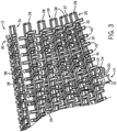
- the cavities 30 do not extend above an upper transport surface 36 of the support plates 28. Therefore, referring to Figs. 2 and 3 , the cavities 30 are formed in the plurality of support plates 28 such that they extend through the lower surface 34 of the support plates 28 but terminate prior to extending to the upper transport surface 36 of the support plates 28. As will be described, this configuration enables the helical conveyer system 12 to move with reduced friction when traversing a spiral path such as shown in Fig. 1 , but will not interfere with objects being transported on the upper transport surface 36 of the plurality of support plates 28.
- the upper transport surface 36 may include a variety of features that advantageously facilitate both transport of objects disposed on the upper transport surface 36 and movement of the helical conveyor 12 along a spiral path.
- substances that increase the coefficient friction of the upper transport surface 36 such as rubber 38, may be disposed in a variety of patterns to aid in fixing objects positioned on the upper transport surface 36 in a given position.
- a plurality of interlocking ribs 40 may be positioned on the upper transport surface 36 or, more specifically, form an upper surface of the upper transport surface 36 to provide a more uniform and substantial upper transport surface 36 while simultaneously allowing the flexing of adjacent support plates 28 necessary to traverse a spiral path, such as shown in Fig. 1 . That is, the reciprocally contoured design of the ribs 40 as disposed on the support plates 28 forms a more substantial upper transport surface 36 as well as permits the support plates 28 to flex as the base chain 14 is curved around a spiral path.
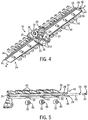
- a single support plate 28 is shown engaged with a portion of the base chain 14.
- the interface 26 between the support plate 28 and base chain 14 is formed as a snap-on connection configured to engage the pins 18 joining the sidebars 16 of the base chain 14.
- an individual support plate 28 may be quickly and easily removed from engagement with the base chain 14 for maintenance or replacement.
- the plurality of rollers 32 are retained within the respective cavities 30 by way of a pin or axle 42 extending through a transverse passage 44 formed within the support plate between the upper transport surface 36 and the lower surface 34. More particularly, the pin 42 is disposed in the transversely extending passage 44, which extends between the pair of side walls 39 joining the upper transport surface 36 and the lower surface 34. Therefore, the pin 42 extends parallel to the transversely extending leading edge 35 and trailing edge 37 that also join the upper transport surface 36 and the lower surface 34.
- each of the rollers 32 includes an opening 46 formed therein that, when disposed within a cavity 30, aligns coaxially with the transversely extending passage 44 such that the pin 42 can be extended through the transversely extending passage 44 and pass through each of the openings 46 formed within the rollers 32. Therefore, the rollers 32 are rotatably secured within the cavities 30.
- a locking mechanism 48 may be utilized that includes a plug or tab 50 configured to engage a recess 52 formed in the support plate 28. That is, once the pin 42 is extended through the transversely extending passages 44 and each respective opening 46 of the plurality of rollers 32, the locking mechanism 48 may be positioned within the end of the transversely extending passage 44 such that the tab 50 engages the recess 52 of the support plate 28 to lock the pin 42 within the transversely extending passage 44.
- the locking mechanism 48 may be integrally formed on an end 54 of the pin 42.
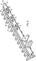
- the support plate 28 includes an alternative system for securing the rollers 32 within the cavities 30.
- the support plate 28 of the present invention includes a pair of locking clips 56 integrally formed within each cavity 30. Accordingly, these clips or snap fittings 56 are configured to engage a set of pins 58 integrally formed with the roller 32 and extending therefrom on either side.
- the roller 32 can be aligned with the cavity 30 and depressed into the passage whereby the pins 58 slide into the snap fitting 56 and to be engaged therewith.
- the snap fittings 56 permit the roller to rotate about an axis 60 extending along the pins 58 while retaining the rollers 32 within the cavity 30.
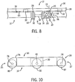
- Fig. 8 a cross-sectional view taken along lines 8--8 of Fig. 4 is shown with the support plate 28 and base chain 14 engaged with the spiral path 10 of Fig. 1 .
- the spiral path 10 includes a recess 62 within which the base chain 14 and associated components are disposed.
- the spiral path 10 includes a first guide surface 64 that is engaged by the rollers 32 and a second guide surface 66 engaged by the roller bearing 24 supported by the pair of arms 20 extending from the sidebar 16 of the base chain 14.
- the support plate 28 is supported on the rollers 32 against the first, horizontally-oriented, guide surface 64.
- the majority of the weight of objects positioned on the helical conveyor system 12 is supported by the rollers 32 through the support plates 28. Accordingly, loading forces associated with the objects positioned on the upper transport surface 36 and frictional forces associated with traversing the spiral path 10 are significantly reduced by the rollers 32 rolling over the first guide surface 64 of the spiral path 10.
- the bearing roller 24 is configured to roll along the second, vertically-oriented, guide surface 66 of the spiral path 10. Additionally, in an effort to resist vertical and horizontal forces that would promote disengaging the helical conveyor system 12 from the spiral path 10, the bearing roller 24 may have a contoured surface such as a lip 68 formed thereon and configured to be received by a reciprocally contoured surface 70 formed in the second bearing surface 66. Though a rotational axis 72 of the bearing roller 24 is shown as being substantially vertical, it is contemplated that the rotational axis 72 may be angled to further facilitate engagement with the reciprocally contoured second guide surface 66.
- the bearing roller 24 includes a less dramatic contour than the lip 68 shown in Fig. 8 , such as an acutely angled depression, it may be desirable to adjust the axis of rotation from the vertical position shown in Fig. 8 to more securely engage the bearing roller 24 with the second guide surface 66.
- the cavities 30 and roller 32 configurations may be utilized with a modular belt.
- a modular link belt 74 designed to follow a straight path is shown that incorporates the roller system which is not part of the present invention.
- the modular belt can be designed to follow a curved path.
- the modular belt 74 also includes a plurality of support plates 28, or belt modules.
- the support plates 28 include link ends 76 along the leading edge 35 configured to engage reciprocally arranged link ends 76 disposed along the trailing edge 37 of an adjacent support plate 28.
- a pin 78 is then passed through coaxially aligned passages formed through the link ends 76 to secure together adjacent support plates 28.
- the support plates 28 include the lower surface 34 and the upper transport surface 36 joined by the leading edge 35, trailing edge 37, and pair of side walls 39.
- the plurality of downwardly opening passages or cavities 30 are again formed within the lower surface 34 of each support plate 28 to house a roller 32.
- the pin 42 may be used to secure the rollers 32 within each cavity 30.
- clips or other similar retaining systems may be utilized instead of the pin 42.
- rollers 80, 82 may be disposed within the links 76 arranged along the leading edge 35 and the trailing edge 37, respectively. Accordingly, three separate sets of rollers 32, 80, 82 can be formed on each support plate 28. However, as shown, none of the rollers 32, 80, 82 extend through the upper transport surface 36.
- a conveyor system is created that significantly reduces torsional, loading, and frictional forces experienced as the conveyor belt traverses a given path. As such, the amount of power required to operate the conveyor system is reduced. Similarly, wear and susceptibility to debris positioned encountered during operation of the conveyor system is significantly reduced. Accordingly, maintenance and upkeep costs associated with operat4ing the conveyor system are also reduced.
Landscapes
- Engineering & Computer Science (AREA)
- Mechanical Engineering (AREA)
- Chain Conveyers (AREA)
- Rollers For Roller Conveyors For Transfer (AREA)
- Fish Paste Products (AREA)
- Replacement Of Web Rolls (AREA)
- Harvester Elements (AREA)
Applications Claiming Priority (3)
| Application Number | Priority Date | Filing Date | Title |
|---|---|---|---|
| US11/290,104 US7556142B2 (en) | 2005-11-30 | 2005-11-30 | Conveyor plate with integrated roller |
| EP06838518A EP1960295B1 (en) | 2005-11-30 | 2006-11-29 | Conveyor plate with integrated roller |
| PCT/US2006/045602 WO2007064659A1 (en) | 2005-11-30 | 2006-11-29 | Conveyor plate with integrated roller |
Related Parent Applications (2)
| Application Number | Title | Priority Date | Filing Date |
|---|---|---|---|
| EP06838518.6 Division | 2006-11-29 | ||
| EP06838518A Division EP1960295B1 (en) | 2005-11-30 | 2006-11-29 | Conveyor plate with integrated roller |
Publications (2)
| Publication Number | Publication Date |
|---|---|
| EP2343253A1 EP2343253A1 (en) | 2011-07-13 |
| EP2343253B1 true EP2343253B1 (en) | 2018-07-11 |
Family
ID=37837001
Family Applications (2)
| Application Number | Title | Priority Date | Filing Date |
|---|---|---|---|
| EP11161823.7A Active EP2343253B1 (en) | 2005-11-30 | 2006-11-29 | Conveyor plate with integrated roller |
| EP06838518A Active EP1960295B1 (en) | 2005-11-30 | 2006-11-29 | Conveyor plate with integrated roller |
Family Applications After (1)
| Application Number | Title | Priority Date | Filing Date |
|---|---|---|---|
| EP06838518A Active EP1960295B1 (en) | 2005-11-30 | 2006-11-29 | Conveyor plate with integrated roller |
Country Status (15)
| Country | Link |
|---|---|
| US (2) | US7556142B2 (da) |
| EP (2) | EP2343253B1 (da) |
| JP (1) | JP2009517306A (da) |
| KR (1) | KR20080080520A (da) |
| CN (1) | CN101316774B (da) |
| AT (1) | ATE506298T1 (da) |
| AU (1) | AU2006320711B9 (da) |
| BR (1) | BRPI0618071A2 (da) |
| CA (1) | CA2628629C (da) |
| DE (1) | DE602006021469D1 (da) |
| DK (1) | DK1960295T3 (da) |
| ES (1) | ES2362537T3 (da) |
| TW (1) | TWI388481B (da) |
| WO (1) | WO2007064659A1 (da) |
| ZA (1) | ZA200803699B (da) |
Families Citing this family (28)
| Publication number | Priority date | Publication date | Assignee | Title |
|---|---|---|---|---|
| EP1902978B1 (en) * | 2006-09-25 | 2013-05-22 | Specialty Conveyor B.V. | Conveyor |
| NL2000404C2 (nl) | 2006-12-22 | 2008-06-25 | Ambaflex Internat B V | Transportinrichting. |
| NL2000635C1 (nl) | 2007-05-07 | 2008-11-10 | Specialty Conveyor Bv | Inrichting en werkwijze voor het bufferen van producten. |
| ATE543760T1 (de) * | 2008-02-01 | 2012-02-15 | System Plast S R L | Förderband mit mehreren scharniermodulen und mitteln zur vermeidung einer axialen verschiebung der modulzapfen |
| NL2002100C (en) | 2008-10-15 | 2010-04-16 | Specialty Conveyor Bv | A buffer conveyor having parallel tracks. |
| IES20090591A2 (en) * | 2009-07-30 | 2010-10-27 | Iaws Technology & Global Services Ltd | A conveyor |
| IT1396487B1 (it) * | 2009-12-04 | 2012-12-14 | Bett Sistemi Srl | Convogliatore. |
| MY172945A (en) * | 2011-05-10 | 2019-12-16 | Flexmove System M Sdn Bhd | A link for a conveyor chain, a conveyor chain made up of said links and a method of operation of said conveyor chain |
| US8646595B2 (en) * | 2011-05-23 | 2014-02-11 | Laitram, L.L.C. | Snap-on conveyor belt rollers |
| US8881890B2 (en) * | 2011-05-23 | 2014-11-11 | Laitram, L.L.C. | Conveyor belt module with fixed axles |
| ES2535278T3 (es) * | 2012-03-27 | 2015-05-07 | Specialty Conveyor B.V. | Transportador |
| MX2015004619A (es) | 2012-10-25 | 2016-01-12 | Solus Ind Innovations Llc | Dispositivos y metodos de indicación de desgaste del sistema de banda transportadora. |
| NL2009781C2 (nl) * | 2012-11-09 | 2014-05-12 | Ambaflex Internat B V | Transporteur. |
| US9751694B2 (en) | 2012-11-29 | 2017-09-05 | Solus Industrial Innovations, Llc | Side-flexing conveyors |
| MX367836B (es) * | 2013-11-12 | 2019-09-09 | Transnorm System Inc | Tira para un transportador. |
| WO2015193907A1 (en) * | 2014-06-19 | 2015-12-23 | Lakhotia Aswini | A flexible element for a conveyor system |
| US9656809B1 (en) * | 2015-12-30 | 2017-05-23 | Agricultural Distributing, Inc. | Bar belt with interdigitized elements |
| CN106005987A (zh) * | 2016-07-01 | 2016-10-12 | 沧州四星玻璃股份有限公司 | 一种螺旋式垂直输送装置 |
| US9745134B1 (en) * | 2016-09-27 | 2017-08-29 | Agricultural Distributing, Inc. | Conveyor belt with rows of alternating types of bars |
| MX2019010524A (es) | 2017-03-08 | 2019-10-15 | Regal Beloit America Inc | Modulo de transferencia para clasificacion de paquetes y sistemas y metodos para el mismo. |
| US10532894B2 (en) | 2017-03-10 | 2020-01-14 | Regal Beloit America, Inc. | Modular transfer units, systems, and methods |
| DE102017004820B3 (de) * | 2017-05-18 | 2018-09-27 | Interroll Holding Ag | Transportaufsatz, Zugmittel, Plattenförderer und Verfahren |
| CN107555088B (zh) * | 2017-08-17 | 2019-04-30 | 广州叁立机械设备有限公司 | 一种紧凑型螺旋升降机 |
| CA3083161A1 (en) | 2017-11-22 | 2019-05-31 | Regal Beloit America, Inc. | Modular sortation units, systems, and methods |
| EP3847112B1 (en) | 2018-09-07 | 2025-05-28 | Cambridge International, Inc. | Modular top flatwire conveyor belt systems and methods |
| EP3853155B1 (en) * | 2018-09-21 | 2024-04-24 | Rexnord Flattop Europe S.r.l. | Link for a chain for an article conveyor |
| CN211168672U (zh) * | 2019-09-04 | 2020-08-04 | 深圳市华南新海传动机械有限公司 | 一种螺旋传送机 |
| CN112849923B (zh) * | 2020-12-31 | 2024-05-17 | 徐州市申克测控机电设备有限公司 | 定量智能螺旋给料系统 |
Citations (2)
| Publication number | Priority date | Publication date | Assignee | Title |
|---|---|---|---|---|
| US5775480A (en) * | 1996-06-14 | 1998-07-07 | The Laitram Corporation | Low-friction conveyor assembly |
| US6401900B1 (en) * | 2000-03-11 | 2002-06-11 | Camillo A. Masciarelli, Jr. | Unidirectional rotating support assemblies and system using such assemblies |
Family Cites Families (43)
| Publication number | Priority date | Publication date | Assignee | Title |
|---|---|---|---|---|
| US5015A (en) * | 1847-03-13 | Mode of producing reciprocating and latkral motions | ||
| US2298386A (en) * | 1939-01-06 | 1942-10-13 | Lamson Corp | Conveyer chain |
| GB1286155A (en) * | 1969-09-15 | 1972-08-23 | Efco Ltd | Conveyors |
| US3627109A (en) * | 1969-09-19 | 1971-12-14 | Richard E Cabak | Conveyor construction |
| US3651924A (en) * | 1970-06-15 | 1972-03-28 | Fmc Corp | Dual bend conveyor |
| US3706371A (en) * | 1970-12-16 | 1972-12-19 | Itaru Hirota | A friction reduced conveying apparatus of helical chain conveyor type |
| US3951256A (en) * | 1971-03-10 | 1976-04-20 | Gurewitz Samuel J | Power belt turn conveyor |
| US3788447A (en) * | 1972-07-03 | 1974-01-29 | Fmc Corp | Linear motor conveyor |
| US3826352A (en) * | 1972-10-27 | 1974-07-30 | Rexnord Inc | Spiral column for endless chain conveyor |
| US3857476A (en) * | 1973-01-29 | 1974-12-31 | Theodore Equipment Corp | Helical endless-belt mechanisms for fuel or empty distray transporting and lifting |
| DD111331A1 (da) * | 1973-07-02 | 1975-02-12 | ||
| US3946857A (en) * | 1973-10-30 | 1976-03-30 | Fraioli Sr Joseph | Conveyor belt system including straight line and curved sections |
| US3854575A (en) * | 1973-10-30 | 1974-12-17 | J Fraioli | Conveyor belt system |
| DK325075A (da) | 1974-08-03 | 1976-02-04 | Amsted Siemag Kette Gmbh | Ledtransportband af flere sammenhengslede plader |
| US3944059A (en) * | 1974-09-20 | 1976-03-16 | Garvey Corporation | Endless chain conveyor link |
| US4159763A (en) * | 1977-08-02 | 1979-07-03 | The Laitram Corporation | Inspectable modular conveyor |
| US4164283A (en) * | 1978-06-26 | 1979-08-14 | The Continental Group, Inc. | Friction-reducing high speed chain guides |
| US4441605A (en) * | 1981-08-28 | 1984-04-10 | Rexnord Inc. | Two-piece snap-on flight for a conveyor chain |
| US4410081A (en) * | 1981-10-26 | 1983-10-18 | Weihe Jr Clyde R | Conveyor system |
| US4458806A (en) * | 1981-12-11 | 1984-07-10 | Weihe Clyde R | Conveyor chain for dishwasher system |
| US4645070A (en) * | 1984-11-07 | 1987-02-24 | Pt Components, Inc. | Dual bend conveyor |
| GB8603408D0 (en) * | 1986-02-12 | 1986-03-19 | Alfa Laval Cheese Systems | Slat conveyor |
| US4867301A (en) * | 1987-08-10 | 1989-09-19 | Ashworth Bros., Inc. | Conveyor belt and system for single direction lateral curved travel |
| JPH02221009A (ja) * | 1989-02-21 | 1990-09-04 | Uingu Haisera:Kk | コンベアベルト |
| DE3914994A1 (de) | 1989-05-06 | 1990-11-08 | Smb Spezialmasch | Plattenkette |
| US5224587A (en) * | 1989-05-16 | 1993-07-06 | Romech Engineering Limited | Improvements in or relating to conveyors |
| CN2084046U (zh) * | 1991-03-05 | 1991-09-04 | 魏佩奇 | 螺旋电梯 |
| US5176247A (en) * | 1991-08-12 | 1993-01-05 | Rexnord Corporation | Sideflexing conveyor chain including low centerline hinge pin |
| US5291987A (en) * | 1993-03-25 | 1994-03-08 | Millard Manufacturing Corp. | Conveyor for raising and lowering articles |
| JPH0738023U (ja) * | 1993-12-27 | 1995-07-14 | 株式会社森川鉄工所 | スパイラルコンベア |
| IT234202Y1 (it) * | 1994-11-08 | 2000-02-23 | Regina Sud Spa | Trasportatore a catena con caratteristiche di scorrimento migliorate |
| US5573105A (en) * | 1995-11-08 | 1996-11-12 | Palmaer; Karl V. | Radius conveyor with guide rollers |
| US5803232A (en) * | 1996-09-06 | 1998-09-08 | Frigoscandia Equipment Ab | Conveyor belt |
| NL1006909C2 (nl) * | 1997-09-02 | 1999-03-04 | Ambaflex B V | Transporteur. |
| US6401914B1 (en) * | 1998-03-12 | 2002-06-11 | The Laitram Corporation | Curved path multiple chain link conveyor modules and belts |
| US6494312B2 (en) * | 1998-11-02 | 2002-12-17 | The Laitram Corporation | Modular roller-top conveyor belt with obliquely-arranged rollers |
| US6364095B1 (en) * | 2000-04-13 | 2002-04-02 | Span Tech Llc | Modular conveyor system with side flexing belt having roller support |
| NL1018994C2 (nl) | 2001-09-20 | 2003-03-21 | Ambaflex Internat B V | Transporteur. |
| US6568522B1 (en) * | 2002-05-16 | 2003-05-27 | The Laitram Corporation | Accumulation system |
| EP1549574B1 (en) * | 2002-05-30 | 2010-07-14 | Laitram, L.L.C. | Low-friction conveyor |
| US6571937B1 (en) * | 2002-09-13 | 2003-06-03 | The Laitram Corporation | Switch conveyor |
| US6578704B1 (en) * | 2002-11-18 | 2003-06-17 | The Laitran Corporation | Belts and belt modules for spiral conveyors |
| US6796418B1 (en) * | 2003-06-26 | 2004-09-28 | Kvp Corporation | Addition of intermediate supports for spiral conveyors |
-
2005
- 2005-11-30 US US11/290,104 patent/US7556142B2/en active Active
-
2006
- 2006-11-29 WO PCT/US2006/045602 patent/WO2007064659A1/en not_active Ceased
- 2006-11-29 ZA ZA200803699A patent/ZA200803699B/xx unknown
- 2006-11-29 AT AT06838518T patent/ATE506298T1/de not_active IP Right Cessation
- 2006-11-29 DK DK06838518.6T patent/DK1960295T3/da active
- 2006-11-29 EP EP11161823.7A patent/EP2343253B1/en active Active
- 2006-11-29 JP JP2008543397A patent/JP2009517306A/ja active Pending
- 2006-11-29 AU AU2006320711A patent/AU2006320711B9/en active Active
- 2006-11-29 CA CA2628629A patent/CA2628629C/en active Active
- 2006-11-29 DE DE602006021469T patent/DE602006021469D1/de active Active
- 2006-11-29 CN CN2006800441421A patent/CN101316774B/zh active Active
- 2006-11-29 EP EP06838518A patent/EP1960295B1/en active Active
- 2006-11-29 ES ES06838518T patent/ES2362537T3/es active Active
- 2006-11-29 KR KR1020087013492A patent/KR20080080520A/ko not_active Withdrawn
- 2006-11-29 BR BRPI0618071-0A patent/BRPI0618071A2/pt active Search and Examination
- 2006-11-30 TW TW095144473A patent/TWI388481B/zh active
-
2009
- 2009-06-04 US US12/478,489 patent/US7854315B2/en not_active Expired - Lifetime
Patent Citations (2)
| Publication number | Priority date | Publication date | Assignee | Title |
|---|---|---|---|---|
| US5775480A (en) * | 1996-06-14 | 1998-07-07 | The Laitram Corporation | Low-friction conveyor assembly |
| US6401900B1 (en) * | 2000-03-11 | 2002-06-11 | Camillo A. Masciarelli, Jr. | Unidirectional rotating support assemblies and system using such assemblies |
Also Published As
| Publication number | Publication date |
|---|---|
| TW200744923A (en) | 2007-12-16 |
| EP1960295B1 (en) | 2011-04-20 |
| CN101316774B (zh) | 2012-05-23 |
| JP2009517306A (ja) | 2009-04-30 |
| US20090236203A1 (en) | 2009-09-24 |
| DK1960295T3 (da) | 2011-08-08 |
| TWI388481B (zh) | 2013-03-11 |
| ZA200803699B (en) | 2009-09-30 |
| AU2006320711B2 (en) | 2010-11-25 |
| EP1960295A1 (en) | 2008-08-27 |
| ES2362537T3 (es) | 2011-07-07 |
| CA2628629A1 (en) | 2007-06-07 |
| AU2006320711B9 (en) | 2011-03-31 |
| KR20080080520A (ko) | 2008-09-04 |
| AU2006320711A1 (en) | 2007-06-07 |
| DE602006021469D1 (de) | 2011-06-01 |
| US7854315B2 (en) | 2010-12-21 |
| ATE506298T1 (de) | 2011-05-15 |
| CA2628629C (en) | 2014-10-14 |
| EP2343253A1 (en) | 2011-07-13 |
| WO2007064659A1 (en) | 2007-06-07 |
| US20070119689A1 (en) | 2007-05-31 |
| CN101316774A (zh) | 2008-12-03 |
| BRPI0618071A2 (pt) | 2011-08-16 |
| US7556142B2 (en) | 2009-07-07 |
Similar Documents
| Publication | Publication Date | Title |
|---|---|---|
| EP2343253B1 (en) | Conveyor plate with integrated roller | |
| US6209716B1 (en) | Knuckle drive link conveyor belt systems with removable load conveying surface members | |
| US5096050A (en) | Low backline pressure chain | |
| US5330045A (en) | Low backline pressure chain | |
| US7681719B2 (en) | Sanitary conveyor transfer tail assembly | |
| US6401914B1 (en) | Curved path multiple chain link conveyor modules and belts | |
| US20130048473A1 (en) | Conveyors and Transmission Belts | |
| EP2105391B1 (en) | Chain link module for accumulating chain | |
| CN105745166A (zh) | 用于输送机的板条 | |
| US4903823A (en) | Spatial conveyor for transferring newspapers, books and magazines | |
| CA2904617C (en) | Conveyor belt and platform for conveyor belt | |
| JPH10503160A (ja) | チェーンコンベヤ | |
| US2689036A (en) | Flush top rider chain for floor conveyers | |
| US7559421B1 (en) | Modular link conveyor chain with return run support arrangement | |
| US7407052B2 (en) | Stabilized guided conveyor belt with multiple base chains and interchangeable conveyor plates | |
| MX2008006722A (en) | Conveyor plate withintegrated roller | |
| EP3670397B1 (en) | Chain guide for cup conveyor | |
| US20060175181A1 (en) | Reduced friction roller support for modular link conveyor chain | |
| JP4090149B2 (ja) | 搬送体牽引用コンベヤ | |
| WO2005014443A1 (en) | Chain link element and conveyor belt with such chain links elements | |
| NL1011801C1 (nl) | Transportsysteem alsmede een kunststof transportketting ten gebruike bij een dergelijk systeem. |
Legal Events
| Date | Code | Title | Description |
|---|---|---|---|
| PUAI | Public reference made under article 153(3) epc to a published international application that has entered the european phase |
Free format text: ORIGINAL CODE: 0009012 |
|
| 17P | Request for examination filed |
Effective date: 20110411 |
|
| AC | Divisional application: reference to earlier application |
Ref document number: 1960295 Country of ref document: EP Kind code of ref document: P |
|
| AK | Designated contracting states |
Kind code of ref document: A1 Designated state(s): AT BE BG CH CY CZ DE DK EE ES FI FR GB GR HU IE IS IT LI LT LU LV MC NL PL PT RO SE SI SK TR |
|
| 17Q | First examination report despatched |
Effective date: 20120608 |
|
| GRAP | Despatch of communication of intention to grant a patent |
Free format text: ORIGINAL CODE: EPIDOSNIGR1 |
|
| INTG | Intention to grant announced |
Effective date: 20160901 |
|
| GRAJ | Information related to disapproval of communication of intention to grant by the applicant or resumption of examination proceedings by the epo deleted |
Free format text: ORIGINAL CODE: EPIDOSDIGR1 |
|
| INTC | Intention to grant announced (deleted) | ||
| GRAP | Despatch of communication of intention to grant a patent |
Free format text: ORIGINAL CODE: EPIDOSNIGR1 |
|
| INTG | Intention to grant announced |
Effective date: 20180207 |
|
| GRAS | Grant fee paid |
Free format text: ORIGINAL CODE: EPIDOSNIGR3 |
|
| GRAA | (expected) grant |
Free format text: ORIGINAL CODE: 0009210 |
|
| AC | Divisional application: reference to earlier application |
Ref document number: 1960295 Country of ref document: EP Kind code of ref document: P |
|
| AK | Designated contracting states |
Kind code of ref document: B1 Designated state(s): AT BE BG CH CY CZ DE DK EE ES FI FR GB GR HU IE IS IT LI LT LU LV MC NL PL PT RO SE SI SK TR |
|
| REG | Reference to a national code |
Ref country code: GB Ref legal event code: FG4D |
|
| REG | Reference to a national code |
Ref country code: CH Ref legal event code: EP |
|
| REG | Reference to a national code |
Ref country code: AT Ref legal event code: REF Ref document number: 1016650 Country of ref document: AT Kind code of ref document: T Effective date: 20180715 |
|
| REG | Reference to a national code |
Ref country code: IE Ref legal event code: FG4D |
|
| REG | Reference to a national code |
Ref country code: DE Ref legal event code: R096 Ref document number: 602006055825 Country of ref document: DE |
|
| REG | Reference to a national code |
Ref country code: NL Ref legal event code: FP |
|
| REG | Reference to a national code |
Ref country code: LT Ref legal event code: MG4D |
|
| REG | Reference to a national code |
Ref country code: AT Ref legal event code: MK05 Ref document number: 1016650 Country of ref document: AT Kind code of ref document: T Effective date: 20180711 |
|
| PG25 | Lapsed in a contracting state [announced via postgrant information from national office to epo] |
Ref country code: FI Free format text: LAPSE BECAUSE OF FAILURE TO SUBMIT A TRANSLATION OF THE DESCRIPTION OR TO PAY THE FEE WITHIN THE PRESCRIBED TIME-LIMIT Effective date: 20180711 Ref country code: LT Free format text: LAPSE BECAUSE OF FAILURE TO SUBMIT A TRANSLATION OF THE DESCRIPTION OR TO PAY THE FEE WITHIN THE PRESCRIBED TIME-LIMIT Effective date: 20180711 Ref country code: PL Free format text: LAPSE BECAUSE OF FAILURE TO SUBMIT A TRANSLATION OF THE DESCRIPTION OR TO PAY THE FEE WITHIN THE PRESCRIBED TIME-LIMIT Effective date: 20180711 Ref country code: BG Free format text: LAPSE BECAUSE OF FAILURE TO SUBMIT A TRANSLATION OF THE DESCRIPTION OR TO PAY THE FEE WITHIN THE PRESCRIBED TIME-LIMIT Effective date: 20181011 Ref country code: AT Free format text: LAPSE BECAUSE OF FAILURE TO SUBMIT A TRANSLATION OF THE DESCRIPTION OR TO PAY THE FEE WITHIN THE PRESCRIBED TIME-LIMIT Effective date: 20180711 Ref country code: SE Free format text: LAPSE BECAUSE OF FAILURE TO SUBMIT A TRANSLATION OF THE DESCRIPTION OR TO PAY THE FEE WITHIN THE PRESCRIBED TIME-LIMIT Effective date: 20180711 Ref country code: IS Free format text: LAPSE BECAUSE OF FAILURE TO SUBMIT A TRANSLATION OF THE DESCRIPTION OR TO PAY THE FEE WITHIN THE PRESCRIBED TIME-LIMIT Effective date: 20181111 Ref country code: GR Free format text: LAPSE BECAUSE OF FAILURE TO SUBMIT A TRANSLATION OF THE DESCRIPTION OR TO PAY THE FEE WITHIN THE PRESCRIBED TIME-LIMIT Effective date: 20181012 |
|
| PG25 | Lapsed in a contracting state [announced via postgrant information from national office to epo] |
Ref country code: ES Free format text: LAPSE BECAUSE OF FAILURE TO SUBMIT A TRANSLATION OF THE DESCRIPTION OR TO PAY THE FEE WITHIN THE PRESCRIBED TIME-LIMIT Effective date: 20180711 Ref country code: LV Free format text: LAPSE BECAUSE OF FAILURE TO SUBMIT A TRANSLATION OF THE DESCRIPTION OR TO PAY THE FEE WITHIN THE PRESCRIBED TIME-LIMIT Effective date: 20180711 |
|
| REG | Reference to a national code |
Ref country code: DE Ref legal event code: R097 Ref document number: 602006055825 Country of ref document: DE |
|
| PG25 | Lapsed in a contracting state [announced via postgrant information from national office to epo] |
Ref country code: EE Free format text: LAPSE BECAUSE OF FAILURE TO SUBMIT A TRANSLATION OF THE DESCRIPTION OR TO PAY THE FEE WITHIN THE PRESCRIBED TIME-LIMIT Effective date: 20180711 Ref country code: RO Free format text: LAPSE BECAUSE OF FAILURE TO SUBMIT A TRANSLATION OF THE DESCRIPTION OR TO PAY THE FEE WITHIN THE PRESCRIBED TIME-LIMIT Effective date: 20180711 Ref country code: CZ Free format text: LAPSE BECAUSE OF FAILURE TO SUBMIT A TRANSLATION OF THE DESCRIPTION OR TO PAY THE FEE WITHIN THE PRESCRIBED TIME-LIMIT Effective date: 20180711 |
|
| PLBE | No opposition filed within time limit |
Free format text: ORIGINAL CODE: 0009261 |
|
| STAA | Information on the status of an ep patent application or granted ep patent |
Free format text: STATUS: NO OPPOSITION FILED WITHIN TIME LIMIT |
|
| PG25 | Lapsed in a contracting state [announced via postgrant information from national office to epo] |
Ref country code: DK Free format text: LAPSE BECAUSE OF FAILURE TO SUBMIT A TRANSLATION OF THE DESCRIPTION OR TO PAY THE FEE WITHIN THE PRESCRIBED TIME-LIMIT Effective date: 20180711 Ref country code: SK Free format text: LAPSE BECAUSE OF FAILURE TO SUBMIT A TRANSLATION OF THE DESCRIPTION OR TO PAY THE FEE WITHIN THE PRESCRIBED TIME-LIMIT Effective date: 20180711 |
|
| 26N | No opposition filed |
Effective date: 20190412 |
|
| REG | Reference to a national code |
Ref country code: CH Ref legal event code: PL |
|
| GBPC | Gb: european patent ceased through non-payment of renewal fee |
Effective date: 20181129 |
|
| PG25 | Lapsed in a contracting state [announced via postgrant information from national office to epo] |
Ref country code: MC Free format text: LAPSE BECAUSE OF FAILURE TO SUBMIT A TRANSLATION OF THE DESCRIPTION OR TO PAY THE FEE WITHIN THE PRESCRIBED TIME-LIMIT Effective date: 20180711 Ref country code: LU Free format text: LAPSE BECAUSE OF NON-PAYMENT OF DUE FEES Effective date: 20181129 |
|
| REG | Reference to a national code |
Ref country code: BE Ref legal event code: MM Effective date: 20181130 |
|
| REG | Reference to a national code |
Ref country code: IE Ref legal event code: MM4A |
|
| PG25 | Lapsed in a contracting state [announced via postgrant information from national office to epo] |
Ref country code: LI Free format text: LAPSE BECAUSE OF NON-PAYMENT OF DUE FEES Effective date: 20181130 Ref country code: SI Free format text: LAPSE BECAUSE OF FAILURE TO SUBMIT A TRANSLATION OF THE DESCRIPTION OR TO PAY THE FEE WITHIN THE PRESCRIBED TIME-LIMIT Effective date: 20180711 Ref country code: CH Free format text: LAPSE BECAUSE OF NON-PAYMENT OF DUE FEES Effective date: 20181130 |
|
| PG25 | Lapsed in a contracting state [announced via postgrant information from national office to epo] |
Ref country code: FR Free format text: LAPSE BECAUSE OF NON-PAYMENT OF DUE FEES Effective date: 20181130 Ref country code: IE Free format text: LAPSE BECAUSE OF NON-PAYMENT OF DUE FEES Effective date: 20181129 |
|
| PG25 | Lapsed in a contracting state [announced via postgrant information from national office to epo] |
Ref country code: BE Free format text: LAPSE BECAUSE OF NON-PAYMENT OF DUE FEES Effective date: 20181130 |
|
| PG25 | Lapsed in a contracting state [announced via postgrant information from national office to epo] |
Ref country code: GB Free format text: LAPSE BECAUSE OF NON-PAYMENT OF DUE FEES Effective date: 20181129 |
|
| PG25 | Lapsed in a contracting state [announced via postgrant information from national office to epo] |
Ref country code: TR Free format text: LAPSE BECAUSE OF FAILURE TO SUBMIT A TRANSLATION OF THE DESCRIPTION OR TO PAY THE FEE WITHIN THE PRESCRIBED TIME-LIMIT Effective date: 20180711 |
|
| PG25 | Lapsed in a contracting state [announced via postgrant information from national office to epo] |
Ref country code: PT Free format text: LAPSE BECAUSE OF FAILURE TO SUBMIT A TRANSLATION OF THE DESCRIPTION OR TO PAY THE FEE WITHIN THE PRESCRIBED TIME-LIMIT Effective date: 20180711 |
|
| PG25 | Lapsed in a contracting state [announced via postgrant information from national office to epo] |
Ref country code: HU Free format text: LAPSE BECAUSE OF FAILURE TO SUBMIT A TRANSLATION OF THE DESCRIPTION OR TO PAY THE FEE WITHIN THE PRESCRIBED TIME-LIMIT; INVALID AB INITIO Effective date: 20061129 Ref country code: CY Free format text: LAPSE BECAUSE OF FAILURE TO SUBMIT A TRANSLATION OF THE DESCRIPTION OR TO PAY THE FEE WITHIN THE PRESCRIBED TIME-LIMIT Effective date: 20180711 |
|
| P01 | Opt-out of the competence of the unified patent court (upc) registered |
Effective date: 20230525 |
|
| PGFP | Annual fee paid to national office [announced via postgrant information from national office to epo] |
Ref country code: NL Payment date: 20251126 Year of fee payment: 20 |
|
| PGFP | Annual fee paid to national office [announced via postgrant information from national office to epo] |
Ref country code: DE Payment date: 20251128 Year of fee payment: 20 |
|
| PGFP | Annual fee paid to national office [announced via postgrant information from national office to epo] |
Ref country code: IT Payment date: 20251119 Year of fee payment: 20 |