EP2343440A1 - Abgasreinigungsvorrichtung für einen verbrennungsmotor - Google Patents
Abgasreinigungsvorrichtung für einen verbrennungsmotor Download PDFInfo
- Publication number
- EP2343440A1 EP2343440A1 EP09824733A EP09824733A EP2343440A1 EP 2343440 A1 EP2343440 A1 EP 2343440A1 EP 09824733 A EP09824733 A EP 09824733A EP 09824733 A EP09824733 A EP 09824733A EP 2343440 A1 EP2343440 A1 EP 2343440A1
- Authority
- EP
- European Patent Office
- Prior art keywords
- exhaust
- exhaust passage
- exhaust gas
- downstream side
- wall surface
- Prior art date
- Legal status (The legal status is an assumption and is not a legal conclusion. Google has not performed a legal analysis and makes no representation as to the accuracy of the status listed.)
- Withdrawn
Links
Images




Classifications
-
- F—MECHANICAL ENGINEERING; LIGHTING; HEATING; WEAPONS; BLASTING
- F01—MACHINES OR ENGINES IN GENERAL; ENGINE PLANTS IN GENERAL; STEAM ENGINES
- F01N—GAS-FLOW SILENCERS OR EXHAUST APPARATUS FOR MACHINES OR ENGINES IN GENERAL; GAS-FLOW SILENCERS OR EXHAUST APPARATUS FOR INTERNAL-COMBUSTION ENGINES
- F01N3/00—Exhaust or silencing apparatus having means for purifying, rendering innocuous, or otherwise treating exhaust
- F01N3/08—Exhaust or silencing apparatus having means for purifying, rendering innocuous, or otherwise treating exhaust for rendering innocuous
- F01N3/10—Exhaust or silencing apparatus having means for purifying, rendering innocuous, or otherwise treating exhaust for rendering innocuous by thermal or catalytic conversion of noxious components of exhaust
- F01N3/24—Exhaust or silencing apparatus having means for purifying, rendering innocuous, or otherwise treating exhaust for rendering innocuous by thermal or catalytic conversion of noxious components of exhaust characterised by constructional aspects of converting apparatus
- F01N3/28—Construction of catalytic reactors
- F01N3/2892—Exhaust flow directors or the like, e.g. upstream of catalytic device
-
- B—PERFORMING OPERATIONS; TRANSPORTING
- B01—PHYSICAL OR CHEMICAL PROCESSES OR APPARATUS IN GENERAL
- B01F—MIXING, e.g. DISSOLVING, EMULSIFYING OR DISPERSING
- B01F23/00—Mixing according to the phases to be mixed, e.g. dispersing or emulsifying
- B01F23/20—Mixing gases with liquids
- B01F23/21—Mixing gases with liquids by introducing liquids into gaseous media
- B01F23/213—Mixing gases with liquids by introducing liquids into gaseous media by spraying or atomising of the liquids
- B01F23/2132—Mixing gases with liquids by introducing liquids into gaseous media by spraying or atomising of the liquids using nozzles
-
- B—PERFORMING OPERATIONS; TRANSPORTING
- B01—PHYSICAL OR CHEMICAL PROCESSES OR APPARATUS IN GENERAL
- B01F—MIXING, e.g. DISSOLVING, EMULSIFYING OR DISPERSING
- B01F25/00—Flow mixers; Mixers for falling materials, e.g. solid particles
- B01F25/20—Jet mixers, i.e. mixers using high-speed fluid streams
- B01F25/25—Mixing by jets impinging against collision plates
-
- F—MECHANICAL ENGINEERING; LIGHTING; HEATING; WEAPONS; BLASTING
- F01—MACHINES OR ENGINES IN GENERAL; ENGINE PLANTS IN GENERAL; STEAM ENGINES
- F01N—GAS-FLOW SILENCERS OR EXHAUST APPARATUS FOR MACHINES OR ENGINES IN GENERAL; GAS-FLOW SILENCERS OR EXHAUST APPARATUS FOR INTERNAL-COMBUSTION ENGINES
- F01N3/00—Exhaust or silencing apparatus having means for purifying, rendering innocuous, or otherwise treating exhaust
- F01N3/08—Exhaust or silencing apparatus having means for purifying, rendering innocuous, or otherwise treating exhaust for rendering innocuous
- F01N3/0807—Exhaust or silencing apparatus having means for purifying, rendering innocuous, or otherwise treating exhaust for rendering innocuous by using absorbents or adsorbents
- F01N3/0828—Exhaust or silencing apparatus having means for purifying, rendering innocuous, or otherwise treating exhaust for rendering innocuous by using absorbents or adsorbents characterised by the absorbed or adsorbed substances
- F01N3/0842—Nitrogen oxides
-
- F—MECHANICAL ENGINEERING; LIGHTING; HEATING; WEAPONS; BLASTING
- F01—MACHINES OR ENGINES IN GENERAL; ENGINE PLANTS IN GENERAL; STEAM ENGINES
- F01N—GAS-FLOW SILENCERS OR EXHAUST APPARATUS FOR MACHINES OR ENGINES IN GENERAL; GAS-FLOW SILENCERS OR EXHAUST APPARATUS FOR INTERNAL-COMBUSTION ENGINES
- F01N3/00—Exhaust or silencing apparatus having means for purifying, rendering innocuous, or otherwise treating exhaust
- F01N3/08—Exhaust or silencing apparatus having means for purifying, rendering innocuous, or otherwise treating exhaust for rendering innocuous
- F01N3/10—Exhaust or silencing apparatus having means for purifying, rendering innocuous, or otherwise treating exhaust for rendering innocuous by thermal or catalytic conversion of noxious components of exhaust
- F01N3/24—Exhaust or silencing apparatus having means for purifying, rendering innocuous, or otherwise treating exhaust for rendering innocuous by thermal or catalytic conversion of noxious components of exhaust characterised by constructional aspects of converting apparatus
- F01N3/28—Construction of catalytic reactors
-
- F—MECHANICAL ENGINEERING; LIGHTING; HEATING; WEAPONS; BLASTING
- F01—MACHINES OR ENGINES IN GENERAL; ENGINE PLANTS IN GENERAL; STEAM ENGINES
- F01N—GAS-FLOW SILENCERS OR EXHAUST APPARATUS FOR MACHINES OR ENGINES IN GENERAL; GAS-FLOW SILENCERS OR EXHAUST APPARATUS FOR INTERNAL-COMBUSTION ENGINES
- F01N2240/00—Combination or association of two or more different exhaust treating devices, or of at least one such device with an auxiliary device, not covered by indexing codes F01N2230/00 or F01N2250/00, one of the devices being
- F01N2240/20—Combination or association of two or more different exhaust treating devices, or of at least one such device with an auxiliary device, not covered by indexing codes F01N2230/00 or F01N2250/00, one of the devices being a flow director or deflector
-
- F—MECHANICAL ENGINEERING; LIGHTING; HEATING; WEAPONS; BLASTING
- F01—MACHINES OR ENGINES IN GENERAL; ENGINE PLANTS IN GENERAL; STEAM ENGINES
- F01N—GAS-FLOW SILENCERS OR EXHAUST APPARATUS FOR MACHINES OR ENGINES IN GENERAL; GAS-FLOW SILENCERS OR EXHAUST APPARATUS FOR INTERNAL-COMBUSTION ENGINES
- F01N2470/00—Structure or shape of exhaust gas passages, pipes or tubes
- F01N2470/18—Structure or shape of exhaust gas passages, pipes or tubes the axis of inlet or outlet tubes being other than the longitudinal axis of apparatus
-
- F—MECHANICAL ENGINEERING; LIGHTING; HEATING; WEAPONS; BLASTING
- F01—MACHINES OR ENGINES IN GENERAL; ENGINE PLANTS IN GENERAL; STEAM ENGINES
- F01N—GAS-FLOW SILENCERS OR EXHAUST APPARATUS FOR MACHINES OR ENGINES IN GENERAL; GAS-FLOW SILENCERS OR EXHAUST APPARATUS FOR INTERNAL-COMBUSTION ENGINES
- F01N3/00—Exhaust or silencing apparatus having means for purifying, rendering innocuous, or otherwise treating exhaust
- F01N3/08—Exhaust or silencing apparatus having means for purifying, rendering innocuous, or otherwise treating exhaust for rendering innocuous
- F01N3/10—Exhaust or silencing apparatus having means for purifying, rendering innocuous, or otherwise treating exhaust for rendering innocuous by thermal or catalytic conversion of noxious components of exhaust
- F01N3/18—Exhaust or silencing apparatus having means for purifying, rendering innocuous, or otherwise treating exhaust for rendering innocuous by thermal or catalytic conversion of noxious components of exhaust characterised by methods of operation; Control
- F01N3/20—Exhaust or silencing apparatus having means for purifying, rendering innocuous, or otherwise treating exhaust for rendering innocuous by thermal or catalytic conversion of noxious components of exhaust characterised by methods of operation; Control specially adapted for catalytic conversion
- F01N3/206—Adding periodically or continuously substances to exhaust gases for promoting purification, e.g. catalytic material in liquid form, NOx reducing agents
- F01N3/2066—Selective catalytic reduction [SCR]
Definitions
- the present invention relates to an exhaust purification system of an internal combustion engine.
- Exhaust gas which is exhausted from an internal combustion engine contains nitrogen oxides (NO X ) and soot and other particulate matter.
- NO X nitrogen oxides
- Various measures are being devised to purify the gas of these ingredients.
- an exhaust purification system which is provided with an engine exhaust passage with a catalyst or particulate filter which has an NO X storage and reduction function (hereinafter referred to as an "NO X storage and reduction catalyst") and is provided with, at the upstream side of the exhaust from this catalyst in this engine exhaust passage, a reducing agent feed system which feeds a reducing agent, may be mentioned.
- a choke is provided which reduces the cross-sectional area of the exhaust flow.
- the choke causes the flow of exhaust gas to accelerate to cause disturbances in the exhaust gas and thereby cause the reducing agent which is fed from the reducing agent feed system to disperse.
- the exhaust purification system which is disclosed in PLT 2 is provided, inside of a catalytic converter at the upstream side of the exhaust purification catalyst, with an exhaust introduction pipe which is capped at its front end and is provided with a plurality of through holes, and a partition wall which is provided with a plurality of through holes.
- the exhaust purification system which is disclosed in PLT 3 is provided, inside of an exhaust pipe between a reducing agent feed system and an exhaust purification catalyst, with a plurality of dispersion plates alternatively arranged.
- an exhaust introduction pipe and partition wall or dispersion plates are used to cause disturbances in the exhaust gas and thereby cause the reducing agent which is fed from the reducing agent feed system to disperse in the exhaust gas.
- the choke, exhaust introduction pipe and partition wall, and dispersion plates which are used in the exhaust purification systems which are described in the above PLTs 1 to 3 all obstruct the flow of exhaust gas so as to cause disturbances in the exhaust gas. For this reason, while it is possible to provide inside of the engine exhaust passage with these components so as to cause the reducing agent to disperse in the exhaust gas, along with this, the pressure loss of the exhaust gas increases. If the pressure loss of the exhaust gas increases in this way, it becomes difficult for exhaust gas to flow out from the combustion chambers of the internal combustion engine and as a result a drop in the engine output, deterioration of the fuel efficiency, etc. are liable to be incurred.
- an object of the present invention is to provide an exhaust purification system of an internal combustion engine which can suppress an increase in the pressure loss of the exhaust gas while causing a reducing agent which is fed from a reducing agent feed system to disperse in the exhaust gas.
- the present invention solves the above problem by means of the provision of the internal combustion engine described in the claims of the claim section.
- an exhaust purification system of an internal combustion engine which is provided with an upstream side exhaust passage through which exhaust gas which is exhausted from the internal combustion engine passes, a downstream side exhaust passage which is arranged at a downstream side of the upstream side exhaust passage at an angle with respect to the upstream side exhaust passage, a reducing agent feeding means which feeds reducing agent into the exhaust gas which passes through the inside of the upstream side exhaust passage, and an exhaust purifying means which is provided inside the downstream side exhaust passage, wherein, the part of the inner wall surface, which defines the downstream side exhaust passage and faces the upstream side exhaust passage outlet, is provided with a flow deflection part, and the flow deflection part is positioned at the upstream side from the exhaust purifying means and is formed so that a velocity component, in an axial direction of a downstream side exhaust passage, of at least part of the flow of exhaust gas which flows into the flow deflection part is oriented in an opposite direction to the direction heading toward the exhaust purifying means.
- the exhaust gas which is oriented in the opposite direction to the direction heading toward the exhaust purifying means strikes the other exhaust gas. Due to this striking action, the exhaust gas is disturbed and the mixing of the reducing agent and exhaust gas is promoted. Further, the flow deflection part only changes the direction of flow of exhaust gas, so substantially no component is provided which would act as a choke with respect to the flow of exhaust gas, and the pressure loss of the exhaust gas is also not increased much at all.
- the region of the wall surface which defines the above flow deflection part at the exhaust purifying means side has a part which is slanted in a direction opposite to the direction heading toward the exhaust purifying means toward the diametrically outward direction of the downstream side exhaust passage.
- an exhaust purification system of an internal combustion engine which is provided with an upstream side exhaust passage through which exhaust gas which is exhausted from the internal combustion engine passes, a downstream side exhaust passage which is arranged at a downstream side of the upstream side exhaust passage at an angle with respect to the upstream side exhaust passage, a reducing agent feeding means which feeds reducing agent into the exhaust gas which passes through the inside of the upstream side exhaust passage, and an exhaust purifying means which is provided inside the downstream side exhaust passage, wherein, the part of the inner wall surface, which defines the downstream side exhaust passage and faces the upstream side exhaust passage outlet, is provided with a flow deflection part, the flow deflection part is positioned at the upstream side from the exhaust purifying means, and a wall surface of the flow deflection part is formed so that at least part of the exhaust gas which strikes part of the wall surface of the flow deflection part and is increased in velocity component in the direction heading toward an exhaust purifying means strikes another part of the wall of surface of the flow deflection
- the exhaust gas which is increased in velocity component in the direction heading toward an exhaust purifying means due to the part of the wall surface of the flow deflection part strikes another part of the wall of surface of the flow deflection part and is lowered in velocity component of the exhaust gas of the direction heading toward the exhaust purifying means.
- the flow deflection part only changes the direction of flow of exhaust gas, so substantially no component is provided which would act as a choke with respect to the flow of exhaust gas and the pressure loss of the exhaust gas is also not increased much at all.
- a region of the wall surface which defines the above flow deflection part at the side away from exhaust purifying means has a part which is slanted in a direction heading toward the exhaust purifying means toward the diametrically outward direction of the downstream side exhaust passage.
- the above flow deflection part is provided with a projecting part which is formed by the inner wall surface, which defines the downstream side exhaust passage, projecting out toward the diametrically outward direction of the downstream side exhaust passage.
- the cross-section of the above projecting part in the circumferential direction of the downstream side exhaust passage is substantially semi elliptical in shape.
- an inlet area of the above projecting part which faces the above downstream side exhaust passage is larger than the cross-sectional area of the upstream side exhaust passage.
- a height, in the axial direction of the downstream side exhaust passage, of the above projecting part is larger than a diameter of the upstream side exhaust passage.
- the above projecting part extends in the circumferential direction of the above downstream side exhaust passage.
- a depth of the above projecting part in the diametrical direction of the downstream side exhaust passage becomes smaller the further from the region which faces the above upstream side exhaust passage outlet.
- the above projecting part is formed so that the outer circumference becomes substantially semi elliptical in shape.
- the above projecting part is slanted so as to be positioned more at the exhaust purifying means side the further away from the region facing said upstream side exhaust passage outlet in the circumferential direction of the downstream side exhaust passage.
- the above upstream side exhaust passage extends, near the outlet thereof, so that a center axis passes though the inside of the projecting part.
- the above upstream side exhaust passage extends, near the outlet thereof, at a slant with respect to a center axis of the downstream side exhaust passage.
- the above upstream side exhaust passage extends, near the outlet thereof, perpendicular to a center axis of the downstream side exhaust passage.
- the above upstream side exhaust passage extends so as to penetrate into the downstream side exhaust passage.
- the above upstream side exhaust passage outlet penetrates into the above projecting part.
- the above flow deflection part is provided with a projecting part which is formed by the inner wall surface, which defines the downstream side exhaust passage, projecting out toward the diametrically outward direction of the downstream side exhaust passage, and a cross-section of the projecting part in a circumferential direction of the downstream side exhaust passage is substantially rectangular.
- the above flow deflection part is provided with a protruding part which projects out from an inner wall surface, which defines the downstream side exhaust passage, toward the diametrically inward direction of the downstream side exhaust passage.
- the above upstream side exhaust passage is defined by an exhaust manifold or an exhaust pipe which is directly connected to the exhaust manifold, and the above downstream side exhaust passage is a corn provided at an upstream part of the catalytic converter which houses the exhaust purifying means.
- FIG. 1 is a view schematically showing an overall internal combustion engine in which the exhaust purification system of the present invention is mounted.
- 1 indicates an engine body, 2 a cylinder block, 3 a piston reciprocating in the cylinder block 2, 4 a cylinder head which is fixed on the cylinder block 2, 5 a combustion chamber which is formed between the piston 3 and the cylinder head 4, 6 an intake valve, 7 an intake port, 8 an exhaust valve, and 9 an exhaust port.
- a spark plug 10 is arranged at the center part of the inner wall surface of the cylinder head 4.
- a fuel injector 11 is arranged at the circumferential region of the inner wall surface of the cylinder head 4. Further, at the top face of the piston 3, a cavity 12 is formed extending from below the fuel injector 11 to below the spark plug 10.
- An intake port 7 of each cylinder is connected through a corresponding intake tube 13 to a surge tank 14.
- the surge tank 14 is connected through an intake duct 15 and air flow meter 16 to an air cleaner (not shown).
- a throttle valve 18 which is driven by a step motor 17 is arranged inside the intake duct 15, a throttle valve 18 which is driven by a step motor 17 is arranged.
- an exhaust port 9 of each cylinder is connected to an exhaust manifold 19.
- This exhaust manifold 19 is connected to a catalytic converter 21 which houses an NO x storage and reduction catalyst 20.
- the catalytic converter 21 houses the NO X storage and reduction catalyst 20, but if a reducing agent has to be fed to purify the exhaust gas, any kind of exhaust purifying means may be housed.
- an exhaust purifying means for example, an oxidation catalyst, a three-way catalyst, a particulate filter, etc. may be mentioned.
- the exhaust manifold 19 is provided with a reducing agent feed system 22 which feeds a reducing agent into the exhaust gas which flows through the exhaust manifold 19. Further, the exhaust manifold 19 and the surge tank 14 are connected to each other via a recirculated exhaust gas (below, referred to as "EGR gas") pipe 26. This EGR gas pipe 26 is provided with an EGR gas control valve 27.
- EGR gas recirculated exhaust gas
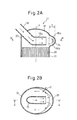
- FIG. 2A and FIG. 2B are enlarged views of the catalytic converter 21 shown in FIG. 1 .
- FIG. 2A is a cross-sectional side view seen from the line A of FIG. 2B
- FIG. 2B is a cross-sectional plan view seen from the line B of FIG. 2A .
- the catalytic converter 21 is provided with a casing 30.
- This casing 30 houses the NO X storage and reduction catalyst 20.
- the casing 30 is provided with a catalyst holder 31 which houses the NO X storage and reduction catalyst 20 and a cone 32 which is provided at an upstream side of the exhaust from the catalyst holder 31.
- These catalyst holder 31 and cone 32 of the casing 30 both define the exhaust passage (downstream side exhaust passage) through which the exhaust gas flows.
- the NO X storage and reduction catalyst 20 and the casing 30 are arranged coaxially. Their axis L extends substantially vertically. Therefore, the exhaust passage which is defined by the casing 30 (that is, the catalyst holder 31 and cone 32) also extends substantially vertically.
- the upstream side in the NO X storage and reduction catalyst 20 will be explained as "upper” while the downstream side will be explained as "lower”.
- the axis L of the NO X storage and reduction catalyst 20 and casing 3 does not necessarily have to extend substantially vertically. It may also be arranged to extend horizontally or in any other direction. Further, the NO X storage and reduction catalyst 20 and the casing 30 do not necessarily have to be arranged coaxially.
- the exhaust manifold 19 is connected to the casing 30. Specifically, the exhaust manifold 19 extends through the wall surface of the cone 32 at the upper part of the cone 32 of the casing 30. Therefore, the exhaust manifold 19 enters into the cone 32. As shown in FIG. 2A and FIG. 2B , the exhaust manifold 19 is slanted with respect to the axis L at the location where it passes through the wall surface of the cone 32.
- the exhaust manifold 19 is bent inside the cone 32 so that the part 19a of the exhaust manifold 19 near the outlet (below, referred to as the "manifold outlet vicinity") extends perpendicular to the axis L, that is, so that it extends perpendicular to the wall surface of the cone 32.
- the outlet of the exhaust manifold 19 faces part of the inner wall surface of the cone 32.
- the thus configured exhaust manifold 19 defines the exhaust passage (upstream side exhaust passage) through which the exhaust gas which is discharged from the engine body 1 flows.
- a projecting part 34 is provided which projects out toward the diametrical direction of the casing 30.
- the upper wall surface 35a of the projecting part 35 is slanted downward toward the diametrically outward direction of the casing 30, while the lower wall surface 35b of the projecting part 35 is slanted upward toward the diametrically outward direction of the casing 30.
- the cross-section of the projecting part 35 in the circumferential direction of the casing 30 is substantially semi elliptical in shape.
- this projecting part 35 extends from the region facing the outlet of the exhaust manifold 19 toward the both circumferential directions of the casing 30. If the length from the inner wall surface of the cone 32 in the case of no projecting part 35 to the part of the projecting part which projects out the most in the diametrical direction of the casing 30 is defined as the depth D of the projecting part 35, the depth D of the projecting part 35 becomes shallower the more away from the region facing the outlet of the exhaust manifold 19 in the circumferential direction of the casing 30. That is, the depth D of the projecting part 35 is deepest at the region facing the outlet of the exhaust manifold 19 and becomes shallower the further from there in the circumferential direction.
- the outer circumference of the projecting part 35 is formed to become substantially semi elliptical in shape. Further, in the present embodiment, the projecting part 35 extends across at least half of the circumference in the circumferential direction of the casing 30.
- FIG. 2A and FIG. 2B show the flow of exhaust gas.
- exhaust gas which is exhausted from the engine body 1 and is fed a reducing agent by the reducing agent feed system 22 flows. Therefore, the exhaust gas which flows through the inside of the exhaust manifold 19 of FIG. 2A and FIG. 2B includes reducing agent which is not sufficiently mixed with the exhaust gas.
- the exhaust gas including the reducing agent which has flowed through the inside of the exhaust manifold 19 flows out from the outlet of the exhaust manifold 19 and flows into the inside of the projecting part 35.
- the exhaust gas which flowed through the bottom of the manifold outlet vicinity 19a strikes the lower wall surface 35b of the projecting part 35. Due to this striking action, the exhaust gas is turned upward in flow direction.
- the exhaust gas which flowed through the top of the manifold outlet vicinity 19a strikes the upper wall surface 35a of the projecting part 35. Due to this striking action, the exhaust gas is turned downward in flow direction.
- the exhaust gas which flows inside of the projecting part 35 strikes the wall surface of the projecting part 35 to change direction of flow in the upward and downward directions. As shown by the arrows in FIG. 2B , it flows along the wall surface of the projecting part 35 toward the both circumferential directions of the casing 30. Due to this, the exhaust gas which flows inside of the projecting part 35 spreads uniformly throughout the casing 30. For this reason, the exhaust gas with which the reducing agent is uniformly mixed flows uniformly into the NO X storage and reduction catalyst 20. Therefore, in the NO X storage and reduction catalyst 20, the reaction with the reducing agent is performed uniformly across the entire NO X storage and reduction catalyst 20 and, for example, the NO X which was stored in the NO X storage and reduction catalyst 20 is optimally purified.
- the reducing agent in the exhaust gas which flows through the inside of the exhaust manifold 19 will sometimes not be sufficiently vaporized at the outlet of the exhaust manifold 19 and will flow out from the exhaust manifold 19 in the droplet state.
- the exhaust manifold 19 and casing 30 of this embodiment even if the reducing agent flows out from the exhaust manifold 19 in the droplet state, almost all of it will flow into the projecting part 35.
- the droplets which flow into the projecting part 35 easily evaporate due to the disturbance in exhaust gas occurring inside the projecting part 35. For this reason, even if the reducing agent flows out from the exhaust manifold 19 in the droplet state, the reducing agent will be kept from flowing into the NO X storage and reduction catalyst 20 and depositing there in the droplet state.
- the projecting part 35 extends by substantially the same length from the region facing the outlet of the exhaust manifold 19 in the both circumferential directions.
- the projecting part 35 does not necessarily have to extend by the same length to the two sides in the circumferential direction. It may also be configured so as to extend longer at one side than the other side.
- the projecting part 35 extends from the region facing the outlet of the exhaust manifold 19 in the circumferential direction, that is, on the plane perpendicular to the axis L.
- the projecting part 35 may also be configured to be slanted with respect to the circumferential direction, that is, to extend at a slant with respect to the plane perpendicular to the axis L.
- the projecting part 35 may also be slanted so as to be positioned lower the further away in the circumferential direction from the region facing the outlet of the exhaust manifold 19.
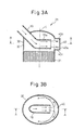
- FIG. 3A and FIG. 3B are enlarged views of the catalytic converter 21 of the second embodiment, similar to FIG. 2A and FIG. 2B .
- the exhaust purification system of the second embodiment is configured basically similar to the configuration of the exhaust purification system of the first embodiment. However, in the exhaust purification system of the first embodiment, the cross-section of the projecting part 35 in the circumferential direction of the casing 30 is substantially semi elliptical in shape, while in the exhaust purification system of the second embodiment, the cross-section of the projecting part 35 in the circumferential direction of the casing 30 is substantially rectangular.
- the projecting part 40 is provided with a vertical wall surface 40a which extends parallel to the axis L, an upper horizontal wall surface 40b which is connected to the top part of the vertical wall surface 40a and which extends perpendicular to the axis L, and a lower horizontal wall surface 40c which is connected to the bottom part of the vertical wall surface 40a and which extends perpendicular to the axis L.
- the flow of exhaust gas in the thus configured exhaust manifold 19 and casing 30 will be explained.
- the exhaust gas which contains the reducing agent and has flowed through the inside of the exhaust manifold 19 flows out from the outlet of the exhaust manifold 19 and flows into the projecting part 40.
- the lower horizontal wall surface 40c of the projecting part 40 extends substantially parallel to the manifold outlet vicinity 19a, so the exhaust gas which flows through the bottom of the manifold outlet vicinity 19a is difficult to strike the lower horizontal wall surface 40c of the projecting part 40, but even so a part of the exhaust gas has a downward velocity component and therefore strikes the lower horizontal wall surface 40c. Due to this striking action, the exhaust gas is turned upward in flow direction and strikes the exhaust gas which flowed out from the exhaust manifold 19 to the inside of the projecting part 40.
- the upper horizontal wall surface 40b of the projecting part 40 also extends substantially parallel to the manifold outlet vicinity 19a, so the exhaust gas which flowed through the top of the manifold outlet vicinity 19a is difficult to strike the upper horizontal wall surface 40b of the projecting part 40, but even so part of the exhaust gas has an upward velocity component and therefore strikes the upper horizontal wall surface 40b. Due to this striking action, the exhaust gas is turned downward in flow direction and strikes the exhaust gas which flowed out from the exhaust manifold 19 to the inside of the projecting part 40.
- part of the exhaust gas which strikes the lower horizontal wall surface 40c of the projecting part 40 to be turned upward in flow direction strikes the upper horizontal wall surface 40b of the projecting part 40.
- the upward velocity component of the exhaust gas is made to fall.
- the exhaust gas is stirred and the mixing of the reducing agent which is contained in the exhaust gas and the exhaust gas is promoted.
- part of the exhaust gas which strikes the upper horizontal wall surface 40b of the projecting part 40 to be turned downward in flow direction strikes the lower horizontal wall surface 40c of the projecting part 40.
- the downward velocity component of the exhaust gas is made to fall.
- the exhaust gas is stirred and the mixing of the reducing agent which is contained in the exhaust gas and the exhaust gas is promoted.
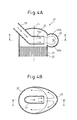
- FIG. 4A and FIG. 4B are enlarged views of the catalytic converter 21 of the third embodiment similar to FIG. 2A and FIG. 2B .
- the exhaust purification system of the third embodiment is configured basically similar to the configuration of the exhaust purification system of the first embodiment. However, in the exhaust purification system of the second embodiment, the cross-section of the projecting part 35 in the circumferential direction of the casing 30 is substantially semi elliptical in shape, while in the exhaust purification system of the third embodiment, the cross-section of the projecting part 45 in the circumferential direction of the casing 30 is substantially circular.
- the projecting part 45 is provided with a upper wall surface 45a which slants once upward toward the diametrically outward direction of the casing 30, then slants downward, and a lower wall surface 45b which slants once downward toward the diametrically outward direction of the casing 30, then slants upward.
- the flow of exhaust gas in the thus configured exhaust manifold 19 and casing 30 will be explained.
- the exhaust gas which contains the reducing agent and flows through the inside of the exhaust manifold 19 flows out from the outlet of the exhaust manifold 19 and flows into the projecting part 45.
- the lower wall surface 45b of the projecting part 45 slants once downward, then slants upward, so when the exhaust gas which flows through the bottom of the manifold outlet vicinity 19a flows into the projecting part 45, first it flows along the downward slanted part of the lower wall surface 45b. After this, it strikes the upward slanted part of the lower wall surface 45b of the projecting part 45. Due to this striking action, the exhaust gas is turned upward in flow direction.
- the upper wall surface 45a of the projecting part 45 slants once upward, then slants downward, so when the exhaust gas which flows through the top of the manifold outlet vicinity 19a flows into the projecting part 45, first it flows along the upward slanted part of the upper wall surface 45a. After this, it strikes the downward slanted part of the upper wall surface 45a of the projecting part 45. Due to this striking action, the exhaust gas is turned downward in flow direction.
- no member is provided which reduces the flow sectional area of the exhaust gas, so it is possible to promote mixing of the reducing agent which is contained in the exhaust gas and the exhaust gas without causing almost any rise in the pressure loss of the exhaust gas.
- the projecting part can be any shape so long as part of its wall surface causes the velocity component in the axial direction of the casing 30 of at least part of the flow of the exhaust gas which flows into the projecting part to be directed upward.
- the projecting part can be any shape so long as at least part of the exhaust gas which strikes the wall surface and is increased in downward velocity component strikes the exhaust gas which is not increased in downward velocity component even if striking the wall surface of the projecting part.
- the exhaust gas which flows through the bottom of the manifold outlet vicinity 19a strikes the lower wall surface of the projecting part and is turned upward in flow direction, then strikes the upper wall surface of this projecting part, whereby the upward velocity component of the exhaust gas is made to fall and, due to this, mixing of the reducing agent and the exhaust gas is promoted. Therefore, it can be said that the projecting part can be any shape so long as it is formed so that at least part of the exhaust gas which strikes part of its wall surface and is increased in velocity component in the direction toward the exhaust purifying means strikes the other part of the wall surface of the projecting part and causes the velocity component of the same direction as this exhaust gas to fall.
- FIG. 5A and FIG. 5B are enlarged views of the catalytic converter 21 of the fourth embodiment, similar to FIG. 2A and FIG. 2B .
- the exhaust purification system of the fourth embodiment is configured basically similar to the configuration of the exhaust purification system of the first embodiment. However, in the exhaust purification system of the first embodiment, the manifold outlet vicinity 19a extends perpendicular with respect to the axis L, while in the present embodiment, the manifold outlet vicinity 50a extends at a slant with respect to the axis L.
- the exhaust manifold 50 of the present embodiment extends passing through the wall surface of the cone 32 at the upper part of the cone 32 of the casing 30.
- the exhaust manifold 50 is slanted with respect to the axis L of the casing 30 at the location passing through the wall surface of the cone 32.
- the exhaust manifold 50 extends straight in the cone 32.
- the manifold outlet vicinity 50a also extends at a slant with respect to the axis L and extends at a slant with respect to the wall surface of the cone 32.
- the manifold outlet vicinity 50a extends toward the projecting part 35.
- the manifold outlet vicinity 50a extends so that its axis M enters the projecting part 35.
- the flow of exhaust gas in the thus configured exhaust manifold 50 and casing 30 will be explained.
- the manifold outlet vicinity 50a extends toward the projecting part 35, so the exhaust gas which contains the reducing agent and flowed through the exhaust manifold 50 flows out from the outlet of the exhaust manifold 50 and into the projecting part 35.
- the exhaust gas which flowed through the bottom of the manifold outlet vicinity 50a strikes the lower wall surface 35b of the projecting part 35. Due to this striking action, the exhaust gas is turned upward in flow direction.
- the exhaust gas which flowed through the top of the manifold outlet vicinity 50a flows along the upper wall surface 35a of the projecting part 35 and is turned downward in flow direction or strikes the upper wall surface 35a and is turned downward in flow direction.
- the exhaust gas which strikes the lower wall surface 35b and is turned upward in flow direction and the exhaust gas which flows along or strikes the upper wall surface 35a and is turned downward in flow direction strike each other, whereby mixing of the reducing agent which is contained in the exhaust gas and the exhaust gas is promoted.
- the exhaust gas which strikes the lower wall surface 35b and is turned upward in flow direction strikes the upper wall surface 35a, while the exhaust gas which strikes the upper wall surface 35a and is turned downward in flow direction strikes the lower wall surface 35a, whereby again mixing of the reducing agent which is contained in the exhaust gas and the exhaust gas is promoted.
- no member is provided which reduces the flow sectional area of the exhaust gas, so it is possible to promote mixing of the reducing agent which is contained in the exhaust gas and the exhaust gas without causing almost any rise in the pressure loss of the exhaust gas.
- the projecting part 35 is preferably configured to extend slanted with respect to the circumferential direction, that is, slanted with respect to the plane perpendicular to the axis L.
- the projecting part 35 slant so as to be positioned lower the further from the region facing the outlet of the exhaust manifold 19 in the circumferential direction, it becomes easier for the exhaust gas which flows thereinto at a slant with respect to the projecting part 35 to flow inside the projecting part 35 in the circumferential direction.
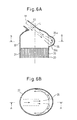
- FIG. 6A and FIG. 6B are enlarged views of the catalytic converter 21 of the fifth embodiment, similar to FIG. 2A and FIG. 2B .
- the exhaust purification system of the fifth embodiment is configured basically similar to the configuration of the exhaust purification system of the fourth embodiment. However, in the exhaust purification system of the fourth embodiment, the exhaust manifold 50 passes through the wall surface of the cone 32 to extend inside of the cone 32, while in the exhaust purification system of the fifth embodiment, the exhaust manifold 55 does not pass through the wall surface of the cone 32 and accordingly does not extend to the inside of the cone 32.
- the exhaust manifold 55 of the present embodiment is directly connected at its outlet part to the cone 32 of the casing 30. Further, the exhaust manifold 55 extends at a slant with respect to the axis L and extends at a slant with respect to the wall surface of the cone 32. Furthermore, as shown in FIG. 6A , the manifold outlet vicinity 55a extends toward the projecting part 35. In other words, the manifold outlet vicinity 55a extends so that its axis M enters inside of the projecting part 35.
- the manifold outlet vicinity 55a extends toward the projecting part 35, so most of the exhaust gas which contains the reducing agent and flows through the exhaust manifold 50 flows out from the outlet of the exhaust manifold 55 and into the projecting part 35.
- the exhaust gas which flows through the bottom of the manifold outlet vicinity 50a strikes the lower wall surface 35b of the projecting part 35 and is turned upward in flow direction.
- the exhaust gas which flows through the top of the manifold outlet vicinity 50a flows along the upper wall surface 35a of the projecting part 35 or strikes the upper wall surface 35a and is turned downward in flow direction.
- the distance from the outlet of the exhaust manifold 55 to the projecting part 35 is long, so part of the exhaust gas which flows out from the outlet of the exhaust manifold 55 does not flow into the projecting part 35, but flows directly into the NO X storage and reduction catalyst 20.
- the direction of flow of exhaust gas suddenly changes, so some pressure loss occurs.
- part of the exhaust gas which flows out from the outlet of the exhaust manifold 55 flows directly into the NO X storage and reduction catalyst 20, so the flow rate of the exhaust gas which flows into the projecting part 35 is reduced and along with this the pressure loss is also reduced.
- no member is provided which narrows the flow sectional area of the exhaust gas. For this reason, in the present embodiment, it is possible to suppress the rise of the pressure loss of the exhaust gas while promoting mixing of the reducing agent which is contained in the exhaust gas and the exhaust gas.
- FIG. 7A and FIG. 7B are enlarged views of the catalytic converter 21 of the sixth embodiment, similar to FIG. 2A and FIG. 2B .
- the exhaust purification system of the sixth embodiment is configured basically similar to the configuration of the exhaust purification system of the first embodiment. However, in the exhaust purification system of the first embodiment, the projecting part 35 extends over at least half of the circumference in the circumferential direction of the casing 30, while in the present embodiment, the projecting part 60 extends over only less than half of the circumference in the circumferential direction of the casing 30.
- the projecting part 60 is small in width W in the circumferential direction of the casing 30, so unlike the projecting part 35 of the first embodiment, the exhaust gas which flows into the projecting part 60 is difficult to flow along the wall surface of the projecting part 60 toward the both circumferential directions of the casing 30. For this reason, in the projecting part 60, the inflowing exhaust gas does not spread in the circumferential direction, so a large disturbance is caused. Due to this as well, mixing of the reducing agent and the exhaust gas is promoted.
- the width W of the inlet of the projecting part 60 acts as a choke and the pressure loss of the exhaust gas increases.
- the width W of the inlet of the projecting part 60 is preferably larger than the diameter "d" of the outlet of the exhaust manifold 19.
- the height of the inlet of the projecting part 60 in the vertical direction is also smaller than the diameter of the outlet of the exhaust manifold 19, the height "h" of the inlet of the projecting part 60 acts as a choke and the pressure loss of the exhaust gas increases.
- the height "h" of the inlet of the projecting part 60 is preferably larger than the diameter "d" of the outlet of the exhaust manifold 19.
- the inlet of the projecting part 60 acts as a choke when the cross-sectional area X of the inlet of the projecting part 60 which faces the space inside the casing 30 (cone 32) becomes smaller than the cross-sectional area of the outlet of the exhaust manifold 19. Therefore, to prevent an increase in the pressure loss of the exhaust gas due to the choke of the inlet of the projecting part 60, it is necessary that the cross-sectional area X of the inlet of the projecting part 60 is smaller than the cross-sectional area of the outlet of the exhaust manifold 19.
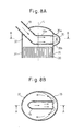
- FIG. 8A and FIG. 8B are enlarged views of the catalytic converter 21 of the seventh embodiment, similar to FIG. 2A and FIG. 2B .
- the exhaust purification system of the seventh embodiment is configured basically similar to the configuration of the exhaust purification system of the first embodiment. However, in the exhaust purification system of the first embodiment, the outlet of the exhaust manifold 19 does not enter inside of the projecting part 35, while in the present embodiment, the outlet of the exhaust manifold 19 enters inside the projecting part 35.
- part of the reducing agent which was fed from the reducing agent feed system 22 sometimes will flow through the inside of the exhaust manifold 19 as droplets without dispersing into the exhaust gas which flows through the inside of the exhaust manifold 19.
- a reducing agent in the droplet state drops down from the outlet of the exhaust manifold 19 in the gravity direction and flows into the NO X storage and reduction catalyst 20. If, in this way, the reducing agent flows into the NO X storage and reduction catalyst 20 in the droplet state without being mixed with the exhaust gas, the exhaust gas may not be sufficiently purified. For this reason, it is necessary that the reducing agent be prevented from flowing into the NO X storage and reduction catalyst 20 in the droplet state.
- the outlet of the exhaust manifold 19 enters inside of the projecting part 35. For this reason, even if the reducing agent drops down from the outlet of the exhaust manifold 19 in the gravity direction in the droplet state, this reducing agent will not directly drop down on to the NO X storage and reduction catalyst 20 and will deposit on the lower wall surface 3b of the projecting part 35.
- the exhaust gas is disturbed, so due to this, the reducing agent in the droplet state which are deposited on the lower wall surface 35b of the projecting part 35 is evaporated, then is mixed with the exhaust gas. Therefore, according to the present embodiment, even if part of the reducing agent which is fed from the reducing agent feed system 22 flows out from the exhaust manifold 19 as is in the droplet state, this reducing agent and exhaust gas can be suitably mixed.
- FIG. 9A and FIG. 9B are enlarged views of the catalytic converter 21 of the eighth embodiment, similar to FIG. 2A and FIG. 2B .
- the exhaust purification system of the eighth embodiment is configured basically similar to the configuration of the exhaust purification system of the first embodiment. However, in the exhaust purification system of the first embodiment, the part of the inner wall surface of the cone 32 which faces the outlet of the exhaust manifold 19 is provided with the projecting part 35, while in the present embodiment, two protruding members 71, 72 are provided which project out toward the diametrically inward direction of the casing 30.
- the lower wall surface 71a of the upper protruding member 71 is slanted downward in the diametrically outward direction of the casing 30. Further, the upper wall surface 71b of the upper protruding member 71 is slanted upward in the diametrically outward direction of the casing 30.
- the upper wall surface 72a of the lower protruding member 72 is slanted upward in the diametrically outward direction of the casing 30, while the lower wall surface 72b of the lower protruding member 72 is slanted downward in the diametrically outward direction of the casing 30.
- the lower wall surface 71a of the upper protruding member 71 and the upper wall surface 72a of the lower protruding member 72 are curved in a concave shape.
- these protruding members 71, 72 extend from the region facing the outlet of the exhaust manifold 19 toward the both circumferential directions of the casing 30. If the length from the inner wall surface of the cone 32 in the case of no protruding members 71, 72 to the part of the protruding members 71, 72 which projects out the most in the diametrical direction of the casing 30 is defined as "D", the depth D of the protruding members 71, 72 becomes shallower the more away from the region facing the outlet of the exhaust manifold 19 in the circumferential direction of the casing 30. In particular, as shown in FIG.
- the inner circumferences of the protruding members 71, 72 are formed to become substantially semi elliptical in shape. Further, in the present embodiment, the protruding members 71, 72 extend across at least half of the circumference in the circumferential direction of the casing 30.
- the inner wall surface of the casing 30 is provided with protruding members 71, 72 separated from the casing 30, but it is also possible to deform the inner wall surface itself of the casing 30 so as to project out to the diametrically inward direction of the casing 30 so as to provide protruding parts at the inner wall surface of the casing 30. Therefore, summarizing these, it can be said that the exhaust purification system of the present embodiment is provided with protruding parts which project out from the inner wall surface defining the casing 30 toward the diametrically inward direction of the casing 30.
- the part of the inner wall surface of the casing 30 which faces the exhaust manifold outlet vicinity 19a is provided with flow deflection parts (for example, the projecting parts 35, 40, 45, 60 and protruding parts 71, 72 provided at the inner wall surface of the above casing 30), and the flow deflection part is positioned at the upstream side from the NO X storage and reduction catalyst 20 and is formed so that the velocity component, in the axial line direction of the casing 30, of the flow of at least part of the exhaust gas which flows into the flow deflection part is directed to the opposite direction from the direction heading toward the NO X storage and reduction catalyst 20.
- flow deflection parts for example, the projecting parts 35, 40, 45, 60 and protruding parts 71, 72 provided at the inner wall surface of the above casing 30
- the part of the inner wall surface of the casing 30 which faces the exhaust manifold outlet vicinity 19a is provided with the flow deflection part, the flow deflection part is provided at the upstream side from the NO X storage and reduction catalyst 20, and the wall surface of the flow deflection part is formed so that at least part of the exhaust gas which strikes part of the wall surface of the flow deflection part and is increased in velocity component in the direction heading toward the NO X storage and reduction catalyst 20 strikes the other part of the wall surface of the flow deflection part and is made to fall in velocity component in the same direction of the exhaust gas.
- the exhaust manifold 19 which was connected to the engine body 1 was directly connected to the casing 30 of the catalytic converter 21, but it is also possible to connect the exhaust pipe which is directly or indirectly connected to the exhaust manifold 19, to the casing 30 of the catalytic converter 21.
- an exhaust purification system for example, by combining the exhaust purification systems of the second embodiment and the fourth embodiment, it is possible to obtain an exhaust purification system where the cross-section of the projecting part in the circumferential direction of the casing 30 is rectangular and where the manifold outlet vicinity extends at a slant with respect to the axis L. Further, for example, by combining the exhaust purification systems of the second embodiment and eighth embodiment, it is possible to obtain an exhaust purification system where the lower wall surface 71a of the upper protruding member 71 and the upper wall surface 72a of the downstream side protruding member 72 are perpendicular to the axial direction of the casing 30.
Landscapes
- Chemical & Material Sciences (AREA)
- Engineering & Computer Science (AREA)
- Chemical Kinetics & Catalysis (AREA)
- Combustion & Propulsion (AREA)
- Mechanical Engineering (AREA)
- General Engineering & Computer Science (AREA)
- Health & Medical Sciences (AREA)
- Toxicology (AREA)
- Exhaust Gas After Treatment (AREA)
- Exhaust Silencers (AREA)
- Exhaust Gas Treatment By Means Of Catalyst (AREA)
Applications Claiming Priority (2)
| Application Number | Priority Date | Filing Date | Title |
|---|---|---|---|
| JP2008284505 | 2008-11-05 | ||
| PCT/JP2009/068543 WO2010053033A1 (ja) | 2008-11-05 | 2009-10-22 | 内燃機関の排気浄化装置 |
Publications (2)
| Publication Number | Publication Date |
|---|---|
| EP2343440A1 true EP2343440A1 (de) | 2011-07-13 |
| EP2343440A4 EP2343440A4 (de) | 2012-12-26 |
Family
ID=42152842
Family Applications (1)
| Application Number | Title | Priority Date | Filing Date |
|---|---|---|---|
| EP09824733A Withdrawn EP2343440A4 (de) | 2008-11-05 | 2009-10-22 | Abgasreinigungsvorrichtung für einen verbrennungsmotor |
Country Status (5)
| Country | Link |
|---|---|
| US (1) | US20110225958A1 (de) |
| EP (1) | EP2343440A4 (de) |
| JP (1) | JP5104960B2 (de) |
| CN (1) | CN102187070A (de) |
| WO (1) | WO2010053033A1 (de) |
Cited By (4)
| Publication number | Priority date | Publication date | Assignee | Title |
|---|---|---|---|---|
| WO2014032685A1 (en) * | 2012-08-31 | 2014-03-06 | Volvo Group Sweden Ab | A gas flow unit, a gas treatment device and a combustion engine provided therewith |
| US9273641B2 (en) | 2012-08-14 | 2016-03-01 | Volvo Truck Corporation | Gas flow unit, a gas treatment device and a combustion engine provided therewith |
| EP3587756A1 (de) * | 2018-06-26 | 2020-01-01 | Mazda Motor Corporation | Abgasvorrichtung eines motors |
| WO2024165407A1 (de) * | 2023-02-07 | 2024-08-15 | Emitec Technologies GmbH | Abgasleitungsvorrichtung zum zuführen von abgas einer brennkraftmaschine an eine katalysatorvorrichtung sowie zweirad |
Families Citing this family (5)
| Publication number | Priority date | Publication date | Assignee | Title |
|---|---|---|---|---|
| FR2972764B1 (fr) | 2011-03-16 | 2013-03-29 | Peugeot Citroen Automobiles Sa | Ensemble compact coude de post-traitement de gaz d'echappement dote d'un bossage formant melangeur de reducteur scr |
| FR2977912B1 (fr) | 2011-07-11 | 2013-07-05 | Peugeot Citroen Automobiles Sa | Ensemble coude de post-traitement des gaz d'echappement d'un moteur a combustion comportant un repartiteur d'agent reducteur par impacteur |
| JP6073659B2 (ja) * | 2012-11-16 | 2017-02-01 | フタバ産業株式会社 | 排ガス浄化装置 |
| US12173632B2 (en) * | 2020-10-22 | 2024-12-24 | Cummins Emission Solutions Inc. | Exhaust gas aftertreatment system |
| JP7472801B2 (ja) * | 2021-01-19 | 2024-04-23 | トヨタ自動車株式会社 | 排気通路 |
Family Cites Families (17)
| Publication number | Priority date | Publication date | Assignee | Title |
|---|---|---|---|---|
| DE2345383A1 (de) * | 1973-09-08 | 1975-03-20 | Daimler Benz Ag | Verbrennungsmotor mit nachverbrennungseinrichtung |
| JPS5222708B2 (de) * | 1973-11-26 | 1977-06-18 | ||
| DE19905032A1 (de) * | 1999-02-08 | 2000-08-10 | Emitec Emissionstechnologie | Abgassystem mit wenigstens einer Leitfläche |
| JP4445137B2 (ja) | 2001-01-12 | 2010-04-07 | 株式会社小松製作所 | エンジンの排気浄化構造 |
| JP3861683B2 (ja) | 2001-12-20 | 2006-12-20 | トヨタ自動車株式会社 | 内燃機関の排気浄化装置 |
| JP4112225B2 (ja) * | 2001-12-27 | 2008-07-02 | トヨタ自動車株式会社 | 排気管構造 |
| EP1712755B1 (de) * | 2004-02-02 | 2011-11-23 | Nissan Diesel Motor Co., Ltd. | Vorrichtung zur abgasreinigung eines motors |
| JP4416162B2 (ja) | 2004-05-13 | 2010-02-17 | 本田技研工業株式会社 | 排気ガス浄化装置 |
| JP2006009793A (ja) * | 2004-05-28 | 2006-01-12 | Yumex Corp | 排気管構造 |
| JP2006077576A (ja) * | 2004-09-07 | 2006-03-23 | Meidensha Corp | 脱硝反応器 |
| JP4641952B2 (ja) * | 2006-02-08 | 2011-03-02 | 本田技研工業株式会社 | 排気触媒装置を備える多気筒内燃機関 |
| US8110151B2 (en) * | 2006-04-03 | 2012-02-07 | Donaldson Company, Inc. | Exhaust flow distribution device |
| DE102006038904A1 (de) * | 2006-08-18 | 2008-02-21 | Emitec Gesellschaft Für Emissionstechnologie Mbh | Verfahren zur Zugabe mindestens eines Reaktanden zu einem Abgasstrom und Vorrichtung zur Aufbereitung eines Abgasstroms einer Verbrennungskraftmaschine |
| DE102006061790A1 (de) * | 2006-12-21 | 2008-06-26 | J. Eberspächer GmbH & Co. KG | Abgasanlage für eine Brennkraftmaschine |
| US7757484B2 (en) * | 2007-01-31 | 2010-07-20 | Caterpillar Inc. | Exhaust treatment device having flow-promoting end caps |
| JP4884332B2 (ja) * | 2007-08-21 | 2012-02-29 | トヨタ自動車株式会社 | 内燃機関の排気システム |
| EP2075428B1 (de) * | 2007-12-25 | 2011-11-16 | Mitsubishi Jidosha Kogyo Kabushiki Kaisha | Emissionssteuerungssystem |
-
2009
- 2009-10-22 JP JP2010536747A patent/JP5104960B2/ja not_active Expired - Fee Related
- 2009-10-22 US US13/127,594 patent/US20110225958A1/en not_active Abandoned
- 2009-10-22 CN CN2009801416100A patent/CN102187070A/zh active Pending
- 2009-10-22 EP EP09824733A patent/EP2343440A4/de not_active Withdrawn
- 2009-10-22 WO PCT/JP2009/068543 patent/WO2010053033A1/ja not_active Ceased
Cited By (5)
| Publication number | Priority date | Publication date | Assignee | Title |
|---|---|---|---|---|
| US9273641B2 (en) | 2012-08-14 | 2016-03-01 | Volvo Truck Corporation | Gas flow unit, a gas treatment device and a combustion engine provided therewith |
| WO2014032685A1 (en) * | 2012-08-31 | 2014-03-06 | Volvo Group Sweden Ab | A gas flow unit, a gas treatment device and a combustion engine provided therewith |
| EP3587756A1 (de) * | 2018-06-26 | 2020-01-01 | Mazda Motor Corporation | Abgasvorrichtung eines motors |
| US10865686B2 (en) | 2018-06-26 | 2020-12-15 | Mazda Motor Corporation | Exhaust device of engine |
| WO2024165407A1 (de) * | 2023-02-07 | 2024-08-15 | Emitec Technologies GmbH | Abgasleitungsvorrichtung zum zuführen von abgas einer brennkraftmaschine an eine katalysatorvorrichtung sowie zweirad |
Also Published As
| Publication number | Publication date |
|---|---|
| JPWO2010053033A1 (ja) | 2012-04-05 |
| EP2343440A4 (de) | 2012-12-26 |
| US20110225958A1 (en) | 2011-09-22 |
| JP5104960B2 (ja) | 2012-12-19 |
| WO2010053033A1 (ja) | 2010-05-14 |
| CN102187070A (zh) | 2011-09-14 |
Similar Documents
| Publication | Publication Date | Title |
|---|---|---|
| EP2343440A1 (de) | Abgasreinigungsvorrichtung für einen verbrennungsmotor | |
| US7992379B2 (en) | Exhaust purification device for engine | |
| CN105673177B (zh) | 具有可更换催化剂壳体的后处理模块 | |
| JP5610120B2 (ja) | エンジンの排気浄化装置 | |
| US7971433B2 (en) | Helical exhaust passage | |
| CN206016918U (zh) | 一种用于筒式净化器的尿素喷射混合单元 | |
| CN203856551U (zh) | 混合器模块以及排放清洁模块 | |
| WO2009093993A1 (en) | Exhaust gas recirculation mixer device | |
| US20140369898A1 (en) | Cross style (4 port) ammonia gas injector | |
| KR101981483B1 (ko) | 배기 가스 정화 장치 | |
| US9556773B2 (en) | Multistage plate mixer | |
| CN102465739B (zh) | 喷射器 | |
| KR102520281B1 (ko) | 스월 혼합형 배기가스 후처리 박스 및 시스템 | |
| US9670816B2 (en) | Exhaust gas aftertreatment device for a combustion engine | |
| US9174167B2 (en) | Mixing plate providing reductant distribution | |
| CN105940196A (zh) | 催化剂容纳盒、排气管道以及发动机 | |
| CN213928500U (zh) | 后处理尿素混合器 | |
| CN210509341U (zh) | 国六后处理器 | |
| CN223724697U (zh) | 一种尿素混合器以及尾气后处理系统 | |
| US9932870B2 (en) | Exhaust gas aftertreatment device for a combustion engine, in particular of a motor vehicle | |
| JP2017110506A (ja) | 排気浄化装置 | |
| US20080163616A1 (en) | Apparatus for Mixing a Liquid Medium Into a Gaseous Medium | |
| CN106567763B (zh) | 用于发动机scr系统的混合装置、发动机scr系统及发动机 | |
| CN213928501U (zh) | 用于尿素混合器的混合管 | |
| CN116677482A (zh) | 混合器组件以及尾气后处理封装 |
Legal Events
| Date | Code | Title | Description |
|---|---|---|---|
| PUAI | Public reference made under article 153(3) epc to a published international application that has entered the european phase |
Free format text: ORIGINAL CODE: 0009012 |
|
| 17P | Request for examination filed |
Effective date: 20110606 |
|
| AK | Designated contracting states |
Kind code of ref document: A1 Designated state(s): AT BE BG CH CY CZ DE DK EE ES FI FR GB GR HR HU IE IS IT LI LT LU LV MC MK MT NL NO PL PT RO SE SI SK SM TR |
|
| AX | Request for extension of the european patent |
Extension state: AL BA RS |
|
| DAX | Request for extension of the european patent (deleted) | ||
| A4 | Supplementary search report drawn up and despatched |
Effective date: 20121128 |
|
| RIC1 | Information provided on ipc code assigned before grant |
Ipc: F01N 3/08 20060101AFI20121122BHEP Ipc: F01N 3/28 20060101ALI20121122BHEP |
|
| RAP1 | Party data changed (applicant data changed or rights of an application transferred) |
Owner name: TOYOTA JIDOSHA KABUSHIKI KAISHA |
|
| RIN1 | Information on inventor provided before grant (corrected) |
Inventor name: INOUE, MIKIO Inventor name: TSUJIMOTO, KENICHI |
|
| GRAP | Despatch of communication of intention to grant a patent |
Free format text: ORIGINAL CODE: EPIDOSNIGR1 |
|
| RIC1 | Information provided on ipc code assigned before grant |
Ipc: B01F 3/04 20060101ALI20141105BHEP Ipc: B01F 5/02 20060101AFI20141105BHEP Ipc: F01N 3/28 20060101ALI20141105BHEP Ipc: F01N 3/08 20060101ALI20141105BHEP Ipc: F01N 3/20 20060101ALI20141105BHEP |
|
| INTG | Intention to grant announced |
Effective date: 20141204 |
|
| STAA | Information on the status of an ep patent application or granted ep patent |
Free format text: STATUS: THE APPLICATION IS DEEMED TO BE WITHDRAWN |
|
| 18D | Application deemed to be withdrawn |
Effective date: 20150415 |