EP2343485A1 - Dispositif facilitant les économies d énergie - Google Patents
Dispositif facilitant les économies d énergie Download PDFInfo
- Publication number
- EP2343485A1 EP2343485A1 EP09818964A EP09818964A EP2343485A1 EP 2343485 A1 EP2343485 A1 EP 2343485A1 EP 09818964 A EP09818964 A EP 09818964A EP 09818964 A EP09818964 A EP 09818964A EP 2343485 A1 EP2343485 A1 EP 2343485A1
- Authority
- EP
- European Patent Office
- Prior art keywords
- energy
- cop
- information
- room
- consumed
- Prior art date
- Legal status (The legal status is an assumption and is not a legal conclusion. Google has not performed a legal analysis and makes no representation as to the accuracy of the status listed.)
- Withdrawn
Links
- 238000004378 air conditioning Methods 0.000 claims description 40
- 238000010586 diagram Methods 0.000 claims description 24
- 238000004364 calculation method Methods 0.000 claims description 7
- 238000004891 communication Methods 0.000 abstract description 61
- 238000000034 method Methods 0.000 description 12
- 238000001704 evaporation Methods 0.000 description 7
- 239000003507 refrigerant Substances 0.000 description 7
- 238000001816 cooling Methods 0.000 description 5
- 230000006870 function Effects 0.000 description 5
- 238000010438 heat treatment Methods 0.000 description 5
- 239000000284 extract Substances 0.000 description 4
- 230000000694 effects Effects 0.000 description 3
- 230000007613 environmental effect Effects 0.000 description 3
- 238000012935 Averaging Methods 0.000 description 2
- 238000005265 energy consumption Methods 0.000 description 2
- 238000009434 installation Methods 0.000 description 2
- 230000010354 integration Effects 0.000 description 2
- 239000004973 liquid crystal related substance Substances 0.000 description 2
- RYGMFSIKBFXOCR-UHFFFAOYSA-N Copper Chemical compound [Cu] RYGMFSIKBFXOCR-UHFFFAOYSA-N 0.000 description 1
- 239000003086 colorant Substances 0.000 description 1
- 238000005094 computer simulation Methods 0.000 description 1
- 229940108928 copper Drugs 0.000 description 1
- 229910052802 copper Inorganic materials 0.000 description 1
- 235000014987 copper Nutrition 0.000 description 1
- 239000010949 copper Substances 0.000 description 1
- 238000006073 displacement reaction Methods 0.000 description 1
- 238000005516 engineering process Methods 0.000 description 1
- 239000011159 matrix material Substances 0.000 description 1
- 238000005057 refrigeration Methods 0.000 description 1
- 239000002699 waste material Substances 0.000 description 1
Images









Classifications
-
- F—MECHANICAL ENGINEERING; LIGHTING; HEATING; WEAPONS; BLASTING
- F24—HEATING; RANGES; VENTILATING
- F24F—AIR-CONDITIONING; AIR-HUMIDIFICATION; VENTILATION; USE OF AIR CURRENTS FOR SCREENING
- F24F11/00—Control or safety arrangements
- F24F11/30—Control or safety arrangements for purposes related to the operation of the system, e.g. for safety or monitoring
- F24F11/46—Improving electric energy efficiency or saving
-
- F—MECHANICAL ENGINEERING; LIGHTING; HEATING; WEAPONS; BLASTING
- F24—HEATING; RANGES; VENTILATING
- F24F—AIR-CONDITIONING; AIR-HUMIDIFICATION; VENTILATION; USE OF AIR CURRENTS FOR SCREENING
- F24F11/00—Control or safety arrangements
- F24F11/70—Control systems characterised by their outputs; Constructional details thereof
-
- F—MECHANICAL ENGINEERING; LIGHTING; HEATING; WEAPONS; BLASTING
- F24—HEATING; RANGES; VENTILATING
- F24F—AIR-CONDITIONING; AIR-HUMIDIFICATION; VENTILATION; USE OF AIR CURRENTS FOR SCREENING
- F24F11/00—Control or safety arrangements
- F24F11/50—Control or safety arrangements characterised by user interfaces or communication
- F24F11/52—Indication arrangements, e.g. displays
-
- F—MECHANICAL ENGINEERING; LIGHTING; HEATING; WEAPONS; BLASTING
- F24—HEATING; RANGES; VENTILATING
- F24F—AIR-CONDITIONING; AIR-HUMIDIFICATION; VENTILATION; USE OF AIR CURRENTS FOR SCREENING
- F24F11/00—Control or safety arrangements
- F24F11/50—Control or safety arrangements characterised by user interfaces or communication
- F24F11/54—Control or safety arrangements characterised by user interfaces or communication using one central controller connected to several sub-controllers
-
- F—MECHANICAL ENGINEERING; LIGHTING; HEATING; WEAPONS; BLASTING
- F24—HEATING; RANGES; VENTILATING
- F24F—AIR-CONDITIONING; AIR-HUMIDIFICATION; VENTILATION; USE OF AIR CURRENTS FOR SCREENING
- F24F11/00—Control or safety arrangements
- F24F11/30—Control or safety arrangements for purposes related to the operation of the system, e.g. for safety or monitoring
- F24F11/46—Improving electric energy efficiency or saving
- F24F11/47—Responding to energy costs
-
- F—MECHANICAL ENGINEERING; LIGHTING; HEATING; WEAPONS; BLASTING
- F24—HEATING; RANGES; VENTILATING
- F24F—AIR-CONDITIONING; AIR-HUMIDIFICATION; VENTILATION; USE OF AIR CURRENTS FOR SCREENING
- F24F2140/00—Control inputs relating to system states
- F24F2140/60—Energy consumption
Definitions
- the present invention relates to an energy saving support device and particularly an energy saving support device that supports energy saving of air conditioners.
- split system air conditioners are often used to effectively regulate the air-conditioned environments inside the building.
- split system air conditioners multiple air conditioners are installed inside a building, so in a building in which split system air conditioners are used, the proportion of the consumed energy of the air conditioners with respect to the consumed energy of the building overall tends to increase as the number of air conditioners installed increases.
- An energy saving support device pertaining to a first aspect of the invention is a device that supports energy saving of an air conditioner.
- the energy saving support device comprises an acquiring unit, a first energy calculating unit, a second energy calculating unit, an information generating unit, and a reporting unit.
- the acquiring unit acquires operating data regarding the air conditioner.
- the first energy calculating unit obtains, on the basis of the operating data that the acquiring unit has acquired, a total consumed energy or a standard consumed energy of the air conditioner as a comparison target energy.
- the second energy calculating unit obtains, on the basis of the operating data that the acquiring unit has acquired, a low-COP consumed energy.
- the low-COP consumed energy is an energy that the air conditioner consumed at a time when it was operating at a COP equal to or less than a predetermined value.
- the information generating unit generates, on the basis of the comparison target energy and the low-COP consumed energy, room-for-energy-saving information for judging whether there is a lot of or little room for energy saving.
- the reporting unit reports the room-for-energy-saving information.
- the room-for-energy-saving information is generated and reported on the basis of the comparison target energy and the low-COP consumed energy.
- examples of the room-for-energy-saving information may include the proportion of the low-COP consumed energy with respect to the total consumed energy and the difference between the standard consumed energy and the low-COP consumed energy. Because of this room-for-energy-saving information, that is, information relating to the consumed energy of the air conditioner, the user can easily grasp the air conditioner in which there is room for energy saving. Consequently, the user can take measures to reduce consumed energy with respect to the air conditioner judged as having a lot of room for energy saving.
- An energy saving support device pertaining to a second aspect of the invention is the energy saving support device pertaining to the first aspect of the invention, wherein the room-for-energy-saving information is the proportion of the low-COP consumed energy with respect to the total consumed energy.
- the proportion of the low-COP consumed energy with respect to the total consumed energy is reported as the room-for-energy-saving information. Because of this, the user can know to what extent the air conditioner is performing an operation with poor efficiency, so the user can grasp how much room there is in which consumed energy can be reduced with respect to the total consumed energy.
- An energy saving support device pertaining to a third aspect of the invention is the energy saving support device pertaining to the second aspect of the invention, wherein the room-for-energy-saving information is information in which the low-COP consumed energy is expressed as a percent in a case where the total consumed energy is 100%.
- the low-COP consumed energy with respect to the total consumed energy is expressed as a percent, so the user can easily grasp how often the air conditioner is performing an operation with poor efficiency.
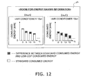
- An energy saving support device pertaining to a fourth aspect of the invention is the energy saving support device pertaining to the first aspect of the invention, wherein the standard consumed energy is an energy that would have been consumed in a case assuming that the COP of the air conditioner had been a predetermined value in the time when the air conditioner was operating at a COP equal to or less than a predetermined value. Additionally, the room-for-energy-saving information is the difference between the standard consumed energy and the low-COP consumed energy.
- the difference between the low-COP consumed energy that was actually consumed at a time when the air conditioner was operating at a COP equal to or less than a predetermined value and the energy (that is, the standard consumed energy) inferred to have been consumed if the COP had been the predetermined value at this time is reported as an index of room for energy saving. Because of this, the user can know to what extent the air conditioner is performing an operation with poor efficiency, so the user can specifically grasp how much room there is in which consumed energy can be reduced.
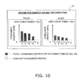
- An energy saving support device pertaining to a fifth aspect of the invention is the energy saving support device pertaining to the first aspect of the invention, wherein the room-for-energy-saving information is information comprising an absolute quantity of the total consumed energy and an absolute quantity of the low-COP consumed energy.
- the reporting unit displays the room-for-energy-saving information such that the absolute quantity of the total consumed energy and the absolute quantity of the low-COP consumed energy relating to the air conditioner are visually graspable.
- the user can visually grasp to what extent the air conditioner is performing an operation with poor efficiency from the absolute quantity of the low-COP consumed energy and the absolute quantity of the total consumed energy that are displayed.
- An energy saving support device pertaining to a sixth aspect of the invention is the energy saving support device pertaining to any of the first to fifth aspects of the invention, wherein the acquiring unit acquires, from a plurality of the air conditioners, the operating data of each of the air conditioners. The first energy calculating unit and the second energy calculating unit calculate the comparison target energy and the low-COP consumed energy for each of the air conditioners. The information generating unit generates the room-for-energy-saving information for each of the air conditioners. Additionally, the reporting unit comparably displays the room-for-energy-saving information of each of the air conditioners.
- the room-for-energy-saving information in each of the plural air conditioners is comparably displayed. For that reason, the user can know at once room for energy saving there is in each air conditioner. Consequently, the user can compare the extent of room for energy saving in each air conditioner, assign priority in descending order of the room for energy saving, for example, and perform measures to reduce consumed energy.
- An energy saving support device pertaining to a seventh aspect of the invention is the energy saving support device pertaining to the sixth aspect of the invention, wherein the reporting unit displays the room-for-energy-saving information of the plurality of the air conditioners inside one diagram or table in order beginning with the room-for-energy-saving information in which the low-COP consumed energy is large.
- the user can know at once, from the room-for-energy-saving information being displayed in descending order of the low-COP consumed energy, which air conditioner of all of the air conditioners has the worst efficiency and which air conditioner of all of the air conditioners has the best efficiency. Consequently, the user can easily judge beginning with which air conditioner an energy-saving measure would best be performed in order.
- An energy saving support device pertaining to an eighth aspect of the invention is the energy saving support device pertaining to the sixth or seventh aspect of the invention, wherein the reporting unit selectably displays the room-for-energy-saving information of the plurality of the air conditioners inside one diagram or table. In a case where the room-for-energy-saving information has been selected, the reporting unit displays in a time series an absolute quantity of the low-COP consumed energy and an absolute quantity of the total consumed energy regarding the air conditioner corresponding to the room-for-energy-saving information that has been selected.
- the room-for-energy-saving information of each air conditioner is being displayed by month.
- the low-COP consumed energy and the total consumed energy (both absolute quantities) regarding the air conditioner corresponding to the room-for-energy-saving information becomes displayed by day. That is, the detailed content of the selected room-for-energy-saving information is displayed more finely in a time series. Because of this, the user can grasp in detail at what point in time an operation with poor efficiency was performed and can take appropriate measures for reducing consumed energy.
- An energy saving support device pertaining to a ninth aspect of the invention is the energy saving support device pertaining to any of the sixth to eighth aspects of the invention, wherein the acquiring unit acquires the operating data from the plurality of the air conditioners which are installed inside one air conditioning target space.
- the plural air conditioners are installed inside one air conditioning target space. According to this energy saving support device, the user can know the room for energy saving in each air conditioner inside the one air conditioning target space and can take measures to reduce consumed energy while considering the temperature inside the air conditioning target space and airflow balance.
- An energy saving support device pertaining to a tenth aspect of the invention is the energy saving support device pertaining to any of the first to ninth aspects of the invention, wherein the reporting unit displays the room-for-energy-saving information together with information relating to date and time.
- the room-for-energy-saving information is displayed together with information relating to date and time. Because of this, the user can know when the air conditioner performed an operation with poor efficiency.
- An energy saving support device pertaining to an eleventh aspect of the invention is the energy saving support device pertaining to any of the first to ninth aspects of the invention, wherein the reporting unit displays the room-for-energy-saving information together with information relating to outside air temperature.
- the room-for-energy-saving information is displayed together with information relating to outside air temperature. Because of this, the user can know in what environmental conditions the efficiency of the air conditioner went down.
- An energy saving support device pertaining to a twelfth aspect of the invention is the energy saving support device pertaining to any of the first to eleventh aspects of the invention, further comprising a third energy calculating unit.
- the third energy calculating unit obtains a high-COP consumed energy.
- the high-COP consumed energy is an energy that the air conditioner consumed at a time when it was operating at a COP equal to or greater than the predetermined value.
- the information generating unit further generates the room-for-energy-saving information on the basis of the high-COP consumed energy.
- the room-for-energy-saving information further generated on the basis of the high-COP consumed energy and not just the low-COP consumed energy is reported. Because of this, the user can not only know the air conditioner that is performing an operation with poor efficiency but can also know the air conditioner that is performing an operation with good efficiency focusing on the high-COP consumed energy.
- An energy saving support device pertaining to a thirteenth aspect of the invention is the energy saving support device pertaining to the twelfth aspect of the invention, wherein the room-for-energy-saving information includes low-COP information relating to the low-COP consumed energy and high-COP information relating to the high-COP consumed energy.
- the reporting unit displays the low-COP information and the high-COP information such that they are visually distinguishable.
- Examples of the low-COP information may include the proportion of the low-COP consumed energy with respect to the total consumed energy and the low-COP consumed energy itself (that is, its absolute quantity).
- Examples of the high-COP information may include the proportion of the high-COP consumed energy with respect to the total consumed energy and the high-COP consumed energy itself (that is, its absolute quantity). According to this energy saving support device, the low-COP information and the high-COP information are displayed such that they are visually distinguishable, so the user can instantly and easily know the good and bad of the efficiency of the operation of each air conditioner.
- An energy saving support device pertaining to a fourteenth aspect of the invention is the energy saving support device pertaining to the twelfth aspect of the invention, wherein the room-for-energy-saving information includes low-COP information relating to the low-COP consumed energy and high-COP information relating to the high-COP consumed energy.
- the reporting unit is further capable of displaying display selection information.
- the display selection information is information for selecting which of the low-COP information and the high-COP information to display.
- the reporting unit displays only the low-COP information of the room-for-energy-saving information in a case where display of the low-COP information has been selected in the display selection information. Further, the reporting unit displays only the high-COP information of the room-for-energy-saving information in a case where display of the high-COP information has been selected in the display selection information.
- this energy saving support device only the low-COP information is displayed if display of the low-COP information is selected and only the high-COP information is displayed if display of the high-COP information is selected. Consequently, the user can set which of the low-COP information and the high-COP information to display according to preference and object.
- An energy saving support device pertaining to a fifteenth aspect of the invention is a device that supports energy saving of an air conditioner.
- the energy saving support device comprises an acquiring unit, a comparison energy calculating unit, a COP energy calculating unit, an information generating unit, and a reporting unit.
- the acquiring unit acquires operating data regarding the air conditioner.
- the comparison energy calculating unit obtains, on the basis of the operating data that the acquiring unit has acquired, a total consumed energy or a standard consumed energy of the air conditioner as a comparison target energy.
- the COP energy calculating unit obtains, on the basis of the operating data that the acquiring unit has acquired, at least one of a high-COP consumed energy and a low-COP consumed energy.
- the high-COP consumed energy is an energy that the air conditioner consumed at a time when it was operating at a COP equal to or greater than a predetermined value.
- the low-COP consumed energy is an energy that the air conditioner consumed at a time when it was operating at a COP equal to or less than the predetermined value.
- the information generating unit generates, on the basis of the calculation result by the COP energy calculating unit and the calculation result of the comparison energy calculating unit, room-for-energy-saving information.
- the room-for-energy-saving information is information for judging whether there is a lot of or little room for energy saving.
- the reporting unit reports the room-for-energy-saving information.
- the room-for-energy-saving information is generated and reported on the basis of the comparison target energy and at least one of the low-COP consumed energy and the high-COP consumed energy.
- examples of the room-for-energy-saving information may include the proportion of the low-COP consumed energy with respect to the total consumed energy, the proportion of the high-COP consumed energy with respect to the total consumed energy, and the difference between the standard consumed energy and the low-COP consumed energy. Because of this room-for-energy-saving information, that is, information relating to the consumed energy of the air conditioner, the user can grasp the air conditioner in which there is room for energy saving. In particular, in a case where the room-for-energy-saving information has been generated on the basis of the high-COP consumed energy, the user can know the air conditioner that is performing an operation with good efficiency.
- the user can easily grasp the air conditioner in which there is room for energy saving. Consequently, the user can take measures to reduce consumed energy with respect to the air conditioner judged as having a lot of room for energy saving.
- the user can know to what extent the air conditioner is performing an operation with poor efficiency, so the user can grasp how much room there is in which consumed energy can be reduced with respect to the total consumed energy.
- the user can easily grasp how often the air conditioner is performing an operation with poor efficiency.
- the user can know to what extent the air conditioner is performing an operation with poor efficiency, so the user can specifically grasp how much room there is in which consumed energy can be reduced.
- the user can visually grasp to what extent the air conditioner is performing an operation with poor efficiency.
- the user can compare the extent of room for energy saving in each air conditioner, assign priority in descending order of the room for energy saving, for example, and perform measures to reduce consumed energy.
- the user can easily judge beginning with which air conditioner an energy-saving measure would best be performed in order.
- the user can grasp in detail at what point in time an operation with poor efficiency was performed and can take appropriate measures for reducing consumed energy.
- the user can know the room for energy saving in each air conditioner inside the one air conditioning target space and can take measures to reduce consumed energy while considering the temperature inside the air conditioning target space and airflow balance.
- the user can know when the air conditioner performed an operation with poor efficiency.
- the user can know in what environmental conditions the efficiency of the air conditioner went down.
- the user can not only know the air conditioner that is performing an operation with poor efficiency but can also know the air conditioner that is performing an operation with good efficiency focusing on the high-COP consumed energy.
- the user can instantly and easily know the good and bad of the efficiency of the operation of each air conditioner.
- the user can set which of the low-COP information and the high-COP information to display according to preference and object.
- the user can grasp the air conditioner in which there is room for energy saving.
- the room-for-energy-saving information has been generated on the basis of the high-COP consumed energy
- the user can know the air conditioner that is performing an operation with good efficiency.
- FIG. 1 is a configuration diagram of an energy saving support system 1 having an energy saving support device 20 pertaining to one embodiment of the present invention.
- the energy saving support system 1 pertaining to the present embodiment is a system used in a building such as a building occupied by multiple offices or multiple tenants.
- the energy saving support system 1 in FIG. 1 is mainly configured by air conditioners 10a and 10e and the energy saving support device 20.
- the air conditioner 10a In the air conditioner 10a, four indoor units 12a, 12b, 12c, and 12d are connected to one outdoor unit 11a, and in the air conditioner 10e, four indoor units 12e, 12f, 12g, and 12h are connected to one outdoor unit 11e. That is, the air conditioners 10a and 10e pertaining to the present embodiment are so-called split system air conditioners.
- Each of the outdoor units 11 a and 11e is installed outside the building, such as on the roof of the building, and each of the indoor units 12a to 12h is installed inside the building.
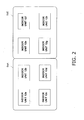
- FIG. 1 and FIG. 2 a case where the indoor units 12a to 12d are installed inside one room SqA in the building (that is, inside one air conditioning target space) and where the indoor units 12e to 12h are installed inside one room SqE in the building (that is, inside one air conditioning target space) will be taken as an example. That is, in the present embodiment, the air conditioners are placed such that one each of the outdoor units 11a and 11e is installed with respect to one room.
- FIG. 1 and FIG. 2 an example where the four indoor units 12a to 12d are connected to the one outdoor unit 11a and where the four indoor units 12e to 12h are connected to the one outdoor unit 11e is shown, but the numbers of the outdoor units 11a and 11e and the indoor units 12a to 12h are not limited to this.
- a case where the two rooms SqA and SqE are disposed inside one building will be taken as example and described, but the number of the rooms disposed inside one building is not limited to this and may be any number.
- the energy saving support device 20 is a device for supporting energy saving of each of the air conditioners 10a and 10e.
- the energy saving support device 20 is connected to each of the outdoor units 11 a and 11e via an air conditioner communication line 91, transmits control commands to each of the outdoor units 11a and 11e, and receives operating data of each of the air conditioners 10a and 10e.
- the operating data will be described in "(2-1) Controller” in "(2) Configuration of Energy Saving Support Device".
- the energy saving support device 20 is connected to an energy meter 50 via a power line 92 and can receive a consumed power of each the air conditioners 10a and 10e sent from the energy meter 50.
- the energy meter 50 is connected in the middle of a power source line 93 extending from the output of a power source 60 to each of the outdoor units 11a and 11e and can measure the power that the power source 60 supplies to each of the outdoor units 11a and 11e and each of the indoor units 12a to 12h. That is, the energy meter 50 can measure the consumed power in the air conditioners 10a and 10e.
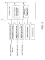
- the energy saving support device 20 pertaining to the present embodiment is configured by a controller 30 and an assist device 40.
- the controller 30 has an air conditioner-use communication unit 31, an energy meter-use communication unit 32 (the air conditioner-use communication unit 31 and the energy meter-use communication unit 32 correspond to an acquiring unit), an assist device-use communication unit 33, an operation panel 34, a storage unit 35, and a control unit 36.
- the air conditioner-use communication unit 31 is for performing communication with the air conditioners 10a and 10e. For example, the air conditioner-use communication unit 31 transmits control orders of each of the indoor units 12a to 12h to each of the outdoor units 11a and 11e via the air conditioner communication line 91 and receives the operating data regarding each of the air conditioners 10a and 10e from each of the outdoor units 11 a and 11e.
- examples of the operating data pertaining to the present embodiment may include data relating to the operating histories and data relating to the operating states of the air conditioners 10a and 10e.
- examples of the data relating to the operating history may include the on and off of the power source of each of the indoor units 12a to 12h, the on and off of a thermostat, various operating modes (specifically, a cooling mode, a heating mode, a fan mode, etc.), set temperature, etc.
- Examples of the data relating to the operating state may include values detected by various sensors and various gauges installed in the air conditioners 10a and 10e (for example, the temperatures inside the rooms; that is, the suction temperatures).
- the air conditioner-use communication unit 31 receives the operating data mentioned above from each of the outdoor units 11 a and 11e. Because of these operating data, the energy saving support device 20 can grasp the operating times of each of the indoor units 12a to 12h, the opening degrees of their indoor expansion valves, their evaporating pressures Pe, their condensing pressures Pc, etc. Moreover, examples of the operating data pertaining to the present embodiment may include the consumed energies of the air conditioners 10a and 10e, but the consumed energies are acquired by the energy meter-use communication unit 32 from the energy meter 50.
- the energy meter-use communication unit 32 is for performing communication with the energy meter 50. As has already been mentioned, the energy meter-use communication unit 32 can receive from the energy meter 50 the consumed energies of the air conditioners 10a and 10e that are one of the operating data. Here, the consumed energies that the energy meter-use communication unit 32 receives correspond to total consumed energies that the air conditioners 10a and 10e have consumed at the time.
- the consumed energies that the energy meter-use communication unit 32 receives respectively correspond to the combined value of the present energy that the one outdoor unit 11 a has consumed and the present energies that the four indoor units 12a to 12d connected to this outdoor unit 11a have consumed, and the combined value of the present energy that the one outdoor unit 11e has consumed and the present power that the four indoor units 12e to 12h connected to this outdoor unit 11e have consumed. That is, the consumed energies correspond to the consumed energy of each of the air conditioners 10a and 10e in each of the rooms SqA and SqE at the time.
- the energy meter-use communication unit 32 can acquire these consumed energies every one minute, for example.
- the assist device-use communication unit 33 is for performing communication with the assist device 40.
- the assist device-use communication unit 33 transmits to the assist device 40 the operating data that the air conditioner-use communication unit 31 has received, total consumed energies Etl that the control unit 36 functioning as a total energy calculating component 36a (described later) has calculated, air conditioning capacities Q that the control unit 36 functioning as an air conditioning capacity calculating component 36b (described later) has calculated, etc.
- the operation panel 34 is a touch panel configured by a liquid crystal display and a matrix switch, for example, and can display various screens. Examples of the screens that the operation panel 34 displays may include a setting screen relating to airflow control of each of the indoor units 12a to 12h that the control unit 36 performs and a screen for allowing each of the indoor units 12a to 12h to be switched on and off. According to this operation panel 34, the user of the energy saving support system 1 can switch each of the indoor units 12a to 12h on and off and perform setting relating to airflow control by directly touching the screens displayed on the screen of the operation panel 34. Moreover, the operation panel 34 can display the operating data of each of the air conditioners 10a and 10e, such as the various operating modes of each of the indoor units 12a to 12h, the set temperatures, the temperatures inside the rooms, etc.
- the storage unit 35 is configured by a HDD or a flash memory and can store operating data regarding each of the air conditioners 10a and 10e. That is, examples of the operating data that the storage unit 35 stores may include the operating data of each of the air conditioners 10a and 10e that the air conditioner-use communication unit 31 has received (excluding the consumed energies of the air conditioners 10a and 10e) and the consumed energies of each of the air conditioners 10a and 10e that the energy meter-use communication unit 32 has received. Moreover, the storage unit 35 can store the total consumed energies Etl that the control unit 36 functioning as the total energy calculating component 36a (described later) has calculated. In view of the storage capacity of the storage unit 35, it is preferable for the storage unit 35 to store the operating data and the total consumed energies Etl from the newest data to until a predetermined period ago.
- the control unit 36 is a microcomputer configured by a CPU and a RAM and performs control of the various units to which it is connected. Specifically, the control unit 36 is connected to the air conditioner-use communication unit 31, the energy meter-use communication unit 32, and the assist device-use communication unit 33 and performs communication control of each of the communication units 31 to 33. Further, the control unit 36 performs generation of control commands based on airflow control and control of the on and off of each of the indoor units 12a and 12h. In particular, the control unit 36 pertaining to the present embodiment performs calculation of the total consumed energy Etl and performs calculation of the air conditioning capacity Q in each of the air conditioners 10a and 10e. Because it performs these actions, the control unit 36 functions as the total energy calculating component 36a (which corresponds to a first energy calculating unit) and the air conditioning capacity calculating component 36b.
- the total energy calculating component 36a calculates, as comparison target energies, the total consumed energy Etl of each of the air conditioners 10a and 10e on the basis of the operating data including the consumed energy of each of the air conditioners 10a and 10e. Specifically, the total energy calculating component 36a calculates, as the total consumed energy, an integrated value in a predetermined period of the consumed energies per system in each of the outdoor units 11 a and 11e. That is, the total energy calculating component 36a calculates the total consumed energy Etl of each of the air conditioners 10a and 10e in the predetermined period per each of the rooms SqA and SqE.
- a total consumed energy Eo which is an integrated value in the predetermined period of the energy that each of the outdoor units 11a and 11e has consumed
- a total consumed energy Elk which is an integrated value in the predetermined period of the energy that each of the indoor units 12a to 12d and 12e to 12f has consumed.
- the total consumed energy Etl pertaining to the present embodiment corresponds to the sum of consumed energy in a state where the coefficient of performance (called "COP" below) of each of the air conditioners 10a and 10e in each of the rooms SqA and SqE is low and consumed energy in a case where the COP is not in a low state.
- COP coefficient of performance
- the low-COP consumed energy consumed energy in a state where the COP is low
- the low-COP consumed energy consumed energy in a state where the COP is low
- details of the low-COP consumed energy will be described in " ⁇ Low-COP Power Calculating Component>”.
- the predetermined period in which the total energy calculating component 36a integrates the energy is one hour, for example. That is, the total energy calculating component 36a integrates the energy it has acquired during one hour and, when one hour passes, resets the integration result and again integrates the energy.
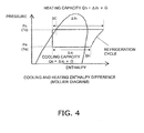
- the air conditioning capacity calculating component 36b estimates the air conditioning capacity Q of each of the air conditioners 10a and 10e on the basis of the operating data of each of the air conditioners 10a and 10e. Specifically, the air conditioning capacity calculating component 36b calculates the air conditioning capacity by multiplying a refrigerant circulation volume G by the enthalpy difference of an evaporator or a condenser in each of the indoor units 12a to 12h.
- the air conditioning capacity calculating component 36b estimates, on the basis of the operating data that the air conditioner-use communication unit 31 has acquired, the enthalpy differences ⁇ ic and ⁇ ih and the refrigerant circulation volume G used in the above calculation. Specifically, the enthalpy differences ⁇ ic and ⁇ ih are obtained by the evaporating pressure Pe, the condensing pressure Pc, and control target values (superheating SH and subcooling SC) grasped by the operating data that the air conditioner-use communication unit 31 has acquired—that is, the data relating to the operating history and the data relating to the operating state of each of the air conditioners 10a and 10e.
- FIG. 4 is a Mollier diagram showing enthalpy differences in cooling and heating, with the horizontal axis representing enthalpy and the vertical axis representing pressure.
- the relationship between the evaporating pressure Pe, the condensing pressure Pc, the superheating SH, the subcooling SC, and the enthalpy differences ⁇ ic and ⁇ ih is shown.
- the saturation temperature Te equivalent to evaporating pressure and the saturation temperature Tc equivalent to condensing pressure are variables respectively decided by the evaporating pressure Pe and the condensing pressure Pc.
- the action of estimating the air conditioning capacities mentioned above is, like the integration of the energy, performed every one hour, for example.
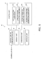
- the assist device 40 has a controller-use communication unit 41, a display unit 42 (which corresponds to a reporting unit), an operation unit 43, a storage unit 44, and a control unit 45.
- the controller-use communication unit 41 is for performing communication with the controller 30 via the assist device-use communication unit 33.
- the controller-use communication unit 41 receives the operating data of each of the air conditioners 10a and 10e, the total consumed energies Etl and the air conditioning capacities that have been calculated by the controller 30, etc.
- the display unit 42 is configured by a liquid crystal display and can display various screens. As shown in FIG. 6 , examples of the screens that the display unit 42 pertaining to the present embodiment displays may include a screen p1 on which the room-for-energy-saving information is displayed.
- the room-for-energy-saving information is information that becomes an index for allowing the user of the energy saving support system 1 to perform energy saving and is generated by the control unit 45 functioning as a room information generating component 45c (described later). Details of the room-for-energy-saving information will be described in " ⁇ Room Information Generating Component>".
- the operation unit 43 comprises a keyboard equipped with alphabetical keys and numerical keys and a pointing device such as a mouse, for example, and is used in a case where the user performs setting of various conditions on the basis of the various screens displayed on the display unit 42.
- the operation unit 43 pertaining to the present embodiment can accept instructions given by the user to read through the room-for-energy-saving information. In this way, the operation unit 43 can accept various operations performed by the user.
- the storage unit 44 is, like the storage unit 35 in the controller 30, configured by a HDD or a flash memory.
- the storage unit 44 can store the operating data, the total consumed energies Etl, the air conditioning capacities, etc. of each of the air conditioners 10a and 10e that the controller-use communication unit 41 has received.
- the storage unit 44 can store the COP of each of the air conditioners 10a and 10e that the control unit 45 functioning as a COP calculating component 45a (described later) has calculated, the low-COP consumed energies that the control unit 45 functioning as a low-COP power calculating component 45b (described later) has calculated, and the room-for-energy-saving information.
- the control unit 45 is, like the control unit 36 pertaining to the controller 30, a microcomputer configured by a CPU and a RAM and performs control of the various units to which it is connected. Specifically, the control unit 45 is connected to the controller-use communication unit 41, the display unit 42, and the operation unit 43 and performs communication control and display control. In particular, the control unit 45 pertaining to the present embodiment performs actions by which it generates information regarding energy saving (that is, the room-for-energy-saving information) and causes the display unit 42 to display this in order to support energy saving with respect to the user of the energy saving support system 1.
- energy saving that is, the room-for-energy-saving information
- control unit 45 functions as the COP calculating component 45a, the low-COP power calculating component 45b (which corresponds to a second energy calculating unit), the room information generating component 45c (which corresponds to an information generating unit), and a screen information generating component 45d.
- the COP calculating component 45a calculates the COP of each of the air conditioners 10a and 10e. In other words, the COP calculating component 45a calculates the COP per system in the single outdoor units 11a and 11e—that is, per each of the rooms SqA and SqE.
- examples of the COP of each of the air conditioners 10a and 10e may include unit COP and system COP, but in the present embodiment, a case where the COP calculating component 45a calculates the system COP will be taken as an example.
- the low-COP power calculating component 45b obtains, on the basis of the operating data of each of the air conditioners 10a and 10e that the controller-use communication unit 41 has received from the controller 30, the low-COP consumed energy that is the energy that each of the air conditioners 10a and 10e consumed when it was operating at a COP equal to or less than a predetermined value.
- the low-COP power calculating component 45b extracts, from the total consumed energy Etl of each of the air conditioners 10a and 10e every predetermined period (that is, every one hour) calculated on the basis of the operating data by the total energy calculating component 36a of the controller 30, the total consumed energy Etl in a case where the COP of each of the air conditioners 10a and 10e obtained by the COP calculating component 45a is equal to or less than 1/2 of a rated COP and uses this as the low-COP consumed energy.
- the low-COP power calculating component 45b decides the total consumed energy Etl of the air conditioner 10a during that time as the low-COP consumed energy.
- the action of calculating the COP of each of the indoor units 12a to 12h pertaining to the present embodiment is performed every one hour, so the low-COP power calculating component 45b performs the above action every one hour.
- the room information generating component 45c generates, on the basis of the total consumed energy and the low-COP consumed energy of each of the air conditioners 10a and 10e, the room-for-energy-saving information for judging whether there is a lot of or little room for energy saving. Specifically, the room information generating component 45c integrates, by month for each of the air conditioners 10a and 10e, the low-COP power consumed energy calculated by the low-COP power calculating component 45b.
- the room information generating component 45c also integrates, by month for each of the air conditioners 10a and 10e, the total consumed energy of each of the air conditioners 10a and 10e obtained by the total energy calculating component 36a (that is, the sum of the consumed energy in a case where the COP is equal to or less than 1/2 of the rated COP and the energy consumption in a case where the COP is not in a low state).
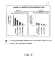
- the room information generating component 45c generates, as the room-for-energy-saving information, the proportion of the low-COP consumed energy during the one month it has integrated (that is, the total consumed energy in a case where the COP was equal to or less than 1/2 of the rated COP) with respect to the total consumed energy during the one month it has integrated for each of the air conditioners 10a and 10e. Because of this, information in which the low-COP consumed energy is expressed as a percent in a case where 100% represents the total consumed energy per month of each of the air conditioners 10a and 10e during one month is obtained as the room-for-energy-saving information (see FIG. 6 ). The room information generating component 45c generates this room-for-energy-saving information in regard to each of the air conditioners 10a and 10e and every predetermined period (here, by month).
- the screen information generating component 45d generates screen information for the room-for-energy-saving information generated by the room information generating component 45c to be displayed on the display unit 42. Specifically, as shown in FIG. 6 , the screen information generating component 45d generates screen information so that the room-for-energy-saving information generated for each of the air conditioners 10a and 10e and per one month is arranged on one screen so that the air conditioners 10a and 10e installed in each of the rooms SqA and SqE inside the one building can be compared. Because of this, as shown in FIG.
- the room-for-energy-saving information of the individual air conditioners 10a and 10e is displayed on one screen on the display unit 42, so it becomes easier for the user utilizing the energy saving support system 1 to judge in which of the rooms SqA and SqE in which the air conditioners 10a and 10e are installed is there a lot of room for energy saving.
- FIG 6 there is shown one example of the screen p1 on which the proportion of the low-COP consumed energy with respect to the total consumed energy of each of the air conditioners 10a and 10e (that is, the sum of the consumed energy in a case where the COP is equal to or less than 1/2 of the rated COP and the consumed energy in a case where the COP is not in a low state) is displayed, with the horizontal axis representing months and the vertical axis representing consumed energy proportion (%). That is, in FIG. 6 , the proportion of the low-COP consumed energy with respect to the total consumed energy of the air conditioners 10a and 10Ee is displayed as a percent together with information relating to date and time. For that reason, it becomes easier for the user to judge how often and when a state where the air conditioner is operating at a COP equal to or less than 1/2 of the rated COP is going on.
- the proportion of the low-COP consumed energy with respect to the total consumed energy of each of the air conditioners 10a and 10e that is, the sum of the consumed
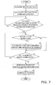
- Steps S1 to S2 When the controller 30 in the energy saving support device 20 acquires the operating data from each of the air conditioners 10a and 10e every one minute (S1), for example, it calculates the total consumed energy Etl of each of the air conditioners 10a and 10e hourly, for example.
- the assist device 40 uses the operating data that the controller 30 has acquired to calculate the COP of each of the air conditioners 10a and 10e hourly (S2).
- the controller 30 repeatedly performs the actions of steps S1 and S2.
- the hourly total consumed energies Etl and COPs that have been calculated are stored in the storage unit 35 of the controller 30.
- Steps S3 to S6 In a case where there is an instruction to read through the room-for-energy-saving information from the user via the operation unit 43 of the assist device 40 (Yes in S3), the assist device 40 starts the action of displaying the room-for-energy-saving information. That is, in a case where there is a COP equal to or less than 1/2 of the rated COP of the hourly COPs of each of the air conditioners 10a and 10e obtained in step S2 (Yes in S4), the assist device 40 uses the total consumed energy Etl of each of the air conditioners 10a and 10e corresponding to this COP as the low-COP consumed energy.
- the assist device 40 integrates, for each of the air conditioners 10a and 10e and by month, the low-COP consumed energy obtained in this way (S5). Further, the assist device 40 also integrates, for each of the air conditioners 10a and 10e and by month, the total consumed energies of the air conditioners 10a and 10e of step S2 calculated every one hour. The assist device 40 performs the actions of steps S4 and S5 for 12 months' worth (S6).
- Step S7 After it has performed the actions of steps S4 and S5 for 12 months' worth in step S6 (Yes in S6), the assist device 40 generates, as the room-for-energy-saving information, the proportion of the low-COP consumed energy with respect to the total consumed energy of each of the air conditioners 10a and 10e during one month in all of the period (that is, 12 months' worth). That is, the assist device 40 performs the action of generating the room-for-energy-saving information for each of the air conditioners 10a and 10e and by month for 12 months' worth.
- Step S8 The assist device 40 arranges and displays the room-for-energy-saving information of each of the air conditioners 10a and 10e such that the room-for-energy-saving information of each of the air conditioners 10a and 10e obtained in step S7 can be compared ( FIG. 6 ).
- the energy saving support device pertaining to the present invention has the advantageous effect that a user can easily grasp air conditioners in which there is room for energy saving, and the energy saving support device pertaining to the present invention can be applied as a device for supporting energy saving of air conditioners.
Landscapes
- Engineering & Computer Science (AREA)
- Chemical & Material Sciences (AREA)
- Combustion & Propulsion (AREA)
- Mechanical Engineering (AREA)
- General Engineering & Computer Science (AREA)
- Human Computer Interaction (AREA)
- Air Conditioning Control Device (AREA)
Applications Claiming Priority (3)
| Application Number | Priority Date | Filing Date | Title |
|---|---|---|---|
| JP2008263219 | 2008-10-09 | ||
| JP2009215411A JP5316335B2 (ja) | 2008-10-09 | 2009-09-17 | 省エネ支援装置 |
| PCT/JP2009/005179 WO2010041424A1 (fr) | 2008-10-09 | 2009-10-06 | Dispositif facilitant les économies d’énergie |
Publications (2)
| Publication Number | Publication Date |
|---|---|
| EP2343485A1 true EP2343485A1 (fr) | 2011-07-13 |
| EP2343485A4 EP2343485A4 (fr) | 2018-05-16 |
Family
ID=42100386
Family Applications (1)
| Application Number | Title | Priority Date | Filing Date |
|---|---|---|---|
| EP09818964.0A Withdrawn EP2343485A4 (fr) | 2008-10-09 | 2009-10-06 | Dispositif facilitant les économies d énergie |
Country Status (8)
| Country | Link |
|---|---|
| US (1) | US8694174B2 (fr) |
| EP (1) | EP2343485A4 (fr) |
| JP (1) | JP5316335B2 (fr) |
| KR (1) | KR20110069100A (fr) |
| CN (1) | CN102177401B (fr) |
| AU (1) | AU2009301912B2 (fr) |
| BR (1) | BRPI0920542A2 (fr) |
| WO (1) | WO2010041424A1 (fr) |
Cited By (5)
| Publication number | Priority date | Publication date | Assignee | Title |
|---|---|---|---|---|
| EP2629165A3 (fr) * | 2012-02-14 | 2014-10-08 | Omron Corporation | Appareil de supervision de système et procédé de commande de celui-ci |
| EP2913598A1 (fr) * | 2013-11-07 | 2015-09-02 | LG Electronics Inc. | Climatiseur et son procédé de fonctionnement |
| FR3041200A1 (fr) * | 2015-09-14 | 2017-03-17 | Swg-Ta | Systeme de calcul d'au moins un parametre relatif a une performance energetique d'un local et procede associe |
| EP3696472A1 (fr) * | 2019-02-18 | 2020-08-19 | Panasonic Intellectual Property Management Co., Ltd. | Procédé de planification d'opération, dispositif de commande d'opération et système de planification d'opération |
| DE102021209792A1 (de) | 2021-09-06 | 2023-03-09 | Robert Bosch Gesellschaft mit beschränkter Haftung | Mehrteiliges klimaanlagensystem und verfahren zum aufteilen eines gesamtenergieverbrauchs eines mehrteiligen klimaanlagensystems |
Families Citing this family (29)
| Publication number | Priority date | Publication date | Assignee | Title |
|---|---|---|---|---|
| JP5621720B2 (ja) * | 2010-07-16 | 2014-11-12 | ダイキン工業株式会社 | エネルギー制御装置 |
| WO2012090522A1 (fr) * | 2010-12-28 | 2012-07-05 | オムロン株式会社 | Dispositif d'estimation d'information de climatisation, procédé de commande de dispositif d'estimation d'information de climatisation, et programme de commande |
| US8849472B2 (en) | 2011-02-02 | 2014-09-30 | Inscope Energy, Llc | Effectuating energization and deactivation of particular circuits through rules-based smart nodes |
| JP5667483B2 (ja) * | 2011-03-17 | 2015-02-12 | アズビル株式会社 | 建物設備運用状態評価方法および装置 |
| JP5528383B2 (ja) * | 2011-03-31 | 2014-06-25 | アズビル株式会社 | 空調管理システム |
| JP6024510B2 (ja) * | 2013-02-22 | 2016-11-16 | 住友電気工業株式会社 | 消費エネルギー分析装置、消費エネルギー分析方法及びコンピュータプログラム |
| JP5840653B2 (ja) * | 2013-07-10 | 2016-01-06 | 三菱電機株式会社 | 空気調和機 |
| US20150046301A1 (en) * | 2013-08-08 | 2015-02-12 | Solavei, Llc | Community-based usage monitoring |
| KR20150038980A (ko) * | 2013-10-01 | 2015-04-09 | 엘지전자 주식회사 | Hvac 컨트롤러 |
| KR20150038978A (ko) | 2013-10-01 | 2015-04-09 | 엘지전자 주식회사 | Hvac 컨트롤러 |
| US20150100164A1 (en) * | 2013-10-04 | 2015-04-09 | Inscope Energy, Llc | Systems and methods for monitoring and/or controlling resources of building structures via a dashboard interface |
| JP6211102B2 (ja) * | 2014-01-27 | 2017-10-11 | ジョンソンコントロールズ ヒタチ エア コンディショニング テクノロジー(ホンコン)リミテッド | 表示装置及びアプリケーションプログラム |
| JP6552795B2 (ja) * | 2014-09-03 | 2019-07-31 | 三菱重工業株式会社 | 省エネルギー支援装置、空調システム、及び空調ネットワークシステム |
| CN107110548B (zh) * | 2015-02-23 | 2019-09-24 | 三菱电机株式会社 | 空调管理装置及使用该空调管理装置的空气调节系统 |
| US10234832B2 (en) * | 2015-09-09 | 2019-03-19 | Honeywell International Inc. | System for optimizing control devices for a space environment |
| CN106871363A (zh) * | 2017-03-07 | 2017-06-20 | 青岛海尔空调器有限总公司 | 空调器 |
| CN106931594A (zh) * | 2017-03-07 | 2017-07-07 | 青岛海尔空调器有限总公司 | 空调器及数据服务器 |
| CN107062530A (zh) * | 2017-03-07 | 2017-08-18 | 青岛海尔空调器有限总公司 | 空调器及数据服务器 |
| CN107101320A (zh) * | 2017-03-07 | 2017-08-29 | 青岛海尔空调器有限总公司 | 空调器及移动终端 |
| CN107101319A (zh) * | 2017-03-07 | 2017-08-29 | 青岛海尔空调器有限总公司 | 空调器及移动终端 |
| CN106839340A (zh) * | 2017-03-16 | 2017-06-13 | 广东美的制冷设备有限公司 | 一种空调制冷量测量方法、装置及空调器 |
| WO2019167138A1 (fr) * | 2018-02-27 | 2019-09-06 | アビームコンサルティング株式会社 | Dispositif d'aide à la réduction d'énergie, programme, et support d'enregistrement sur lequel un programme est enregistré |
| KR102123950B1 (ko) * | 2018-09-21 | 2020-06-17 | 에이치디씨아이콘트롤스주식회사 | 에너지 절감현황 표시 시스템, 및 방법 |
| CN109114759B (zh) * | 2018-10-15 | 2020-05-22 | 广东美的制冷设备有限公司 | 控制终端、一拖多空调器的控制方法及装置和存储介质 |
| JP7431535B2 (ja) * | 2019-09-06 | 2024-02-15 | シャープ株式会社 | サーバおよび制御システム、並びに制御プログラム |
| CN110726221B (zh) * | 2019-10-29 | 2020-09-25 | 珠海格力电器股份有限公司 | 确定空调能效信息的方法、装置和空调 |
| CN112524750A (zh) * | 2020-11-03 | 2021-03-19 | 上海工程技术大学 | 冷水及空调机组能效监测方法、装置、设备及存储介质 |
| JP7493086B1 (ja) | 2023-08-18 | 2024-05-30 | 東芝ライフスタイル株式会社 | アプリケーションプログラム、端末装置、家電機器管理システム、および家電機器管理方法 |
| KR102759809B1 (ko) * | 2024-06-03 | 2025-01-24 | 주식회사 동성이에스 | 산업용 전동기의 전력부하최적화를 이용한 에너지 절감 솔루션 제공 시스템 |
Family Cites Families (18)
| Publication number | Priority date | Publication date | Assignee | Title |
|---|---|---|---|---|
| JPS60583Y2 (ja) * | 1980-11-26 | 1985-01-09 | 建三 各務 | カウンタ−付冷暖房装置 |
| JP2001099465A (ja) * | 1999-09-30 | 2001-04-13 | Toshiba Kyaria Kk | 空気調和機 |
| JP2002002156A (ja) * | 2000-06-26 | 2002-01-08 | Sekisui House Ltd | 住宅の省エネルギー効果を表示するための表示物 |
| JP2002115885A (ja) * | 2000-10-10 | 2002-04-19 | Matsushita Seiko Co Ltd | 空気調和機のエネルギー管理システム |
| JP4334176B2 (ja) * | 2002-01-22 | 2009-09-30 | 株式会社東芝 | 建物省エネルギー評価監視装置 |
| JP4147868B2 (ja) | 2002-08-27 | 2008-09-10 | ダイキン工業株式会社 | エネルギー診断システムおよびエネルギー診断装置 |
| JP2004085085A (ja) | 2002-08-27 | 2004-03-18 | Rinnai Corp | ガス調理器具 |
| EP1489719A3 (fr) * | 2003-06-20 | 2007-05-02 | Matsushita Electric Industrial Co., Ltd. | système de gestion d'énergie, procédé de gestion d'énergie et unité fournissant des informations sur un équipement recommandé économiseur d'énergie |
| KR100550556B1 (ko) * | 2003-11-11 | 2006-02-10 | 엘지전자 주식회사 | 에어컨의 중앙제어 시스템 및 그 동작방법 |
| US20060065750A1 (en) * | 2004-05-21 | 2006-03-30 | Fairless Keith W | Measurement, scheduling and reporting system for energy consuming equipment |
| JP4342473B2 (ja) * | 2004-06-09 | 2009-10-14 | 三洋電機株式会社 | 機器制御システム |
| JP4505363B2 (ja) * | 2005-03-29 | 2010-07-21 | 東洋熱工業株式会社 | 空調システムの冷温水制御方法 |
| JP4498196B2 (ja) * | 2005-04-11 | 2010-07-07 | 三機工業株式会社 | 空調システムの表示装置 |
| JP4501930B2 (ja) * | 2006-12-08 | 2010-07-14 | 三菱電機株式会社 | 空気調和装置 |
| JP4151727B2 (ja) * | 2006-12-22 | 2008-09-17 | ダイキン工業株式会社 | 空調管理装置 |
| WO2008088031A1 (fr) * | 2007-01-17 | 2008-07-24 | Daikin Industries, Ltd. | Appareil de conditionnement d'air |
| JP2008232531A (ja) * | 2007-03-20 | 2008-10-02 | Toshiba Corp | リモート性能監視装置及びリモート性能監視方法 |
| US8949073B2 (en) * | 2008-08-19 | 2015-02-03 | Daikin Industries, Ltd. | Diagnostic aid device |
-
2009
- 2009-09-17 JP JP2009215411A patent/JP5316335B2/ja not_active Expired - Fee Related
- 2009-10-06 CN CN2009801396588A patent/CN102177401B/zh not_active Expired - Fee Related
- 2009-10-06 WO PCT/JP2009/005179 patent/WO2010041424A1/fr not_active Ceased
- 2009-10-06 AU AU2009301912A patent/AU2009301912B2/en not_active Ceased
- 2009-10-06 BR BRPI0920542A patent/BRPI0920542A2/pt not_active IP Right Cessation
- 2009-10-06 KR KR1020117008688A patent/KR20110069100A/ko not_active Ceased
- 2009-10-06 US US13/122,528 patent/US8694174B2/en not_active Expired - Fee Related
- 2009-10-06 EP EP09818964.0A patent/EP2343485A4/fr not_active Withdrawn
Non-Patent Citations (1)
| Title |
|---|
| See references of WO2010041424A1 * |
Cited By (6)
| Publication number | Priority date | Publication date | Assignee | Title |
|---|---|---|---|---|
| EP2629165A3 (fr) * | 2012-02-14 | 2014-10-08 | Omron Corporation | Appareil de supervision de système et procédé de commande de celui-ci |
| EP2913598A1 (fr) * | 2013-11-07 | 2015-09-02 | LG Electronics Inc. | Climatiseur et son procédé de fonctionnement |
| US9696047B2 (en) | 2013-11-07 | 2017-07-04 | Lg Electronics Inc. | Air conditioner and method for operating an air conditioner |
| FR3041200A1 (fr) * | 2015-09-14 | 2017-03-17 | Swg-Ta | Systeme de calcul d'au moins un parametre relatif a une performance energetique d'un local et procede associe |
| EP3696472A1 (fr) * | 2019-02-18 | 2020-08-19 | Panasonic Intellectual Property Management Co., Ltd. | Procédé de planification d'opération, dispositif de commande d'opération et système de planification d'opération |
| DE102021209792A1 (de) | 2021-09-06 | 2023-03-09 | Robert Bosch Gesellschaft mit beschränkter Haftung | Mehrteiliges klimaanlagensystem und verfahren zum aufteilen eines gesamtenergieverbrauchs eines mehrteiligen klimaanlagensystems |
Also Published As
| Publication number | Publication date |
|---|---|
| US8694174B2 (en) | 2014-04-08 |
| BRPI0920542A2 (pt) | 2019-09-24 |
| CN102177401A (zh) | 2011-09-07 |
| CN102177401B (zh) | 2013-07-24 |
| EP2343485A4 (fr) | 2018-05-16 |
| US20110190954A1 (en) | 2011-08-04 |
| JP5316335B2 (ja) | 2013-10-16 |
| AU2009301912B2 (en) | 2013-02-07 |
| JP2010112697A (ja) | 2010-05-20 |
| AU2009301912A1 (en) | 2010-04-15 |
| KR20110069100A (ko) | 2011-06-22 |
| WO2010041424A1 (fr) | 2010-04-15 |
Similar Documents
| Publication | Publication Date | Title |
|---|---|---|
| AU2009301912B2 (en) | Energy saving support device | |
| US8949073B2 (en) | Diagnostic aid device | |
| US8670871B2 (en) | Load processing balance setting apparatus | |
| AU2009275114B2 (en) | Group Management Apparatus and Group Management System | |
| JP4396779B2 (ja) | 空調機管理装置 | |
| JP2010048433A (ja) | 診断支援装置 | |
| EP4019856B1 (fr) | Dispositif de traitement d'informations | |
| JP2014236605A (ja) | 空気調和装置の管理システム | |
| US20080142607A1 (en) | Air conditioning system and method of controlling the same | |
| JP5473619B2 (ja) | 空気調和機の制御装置 | |
| JP2019211108A (ja) | 空調管理システム及び通信制御装置 | |
| WO2016186069A1 (fr) | Dispositif de présentation de montant de prédiction de prime | |
| JP2021081167A (ja) | 空調機のショートサーキット評価装置 | |
| Knight et al. | HARMONAC: Quantifying the Energy Conservation Opportunities in Air-Conditioning Inspections as required by EPBD Article 9 |
Legal Events
| Date | Code | Title | Description |
|---|---|---|---|
| PUAI | Public reference made under article 153(3) epc to a published international application that has entered the european phase |
Free format text: ORIGINAL CODE: 0009012 |
|
| 17P | Request for examination filed |
Effective date: 20110419 |
|
| AK | Designated contracting states |
Kind code of ref document: A1 Designated state(s): AT BE BG CH CY CZ DE DK EE ES FI FR GB GR HR HU IE IS IT LI LT LU LV MC MK MT NL NO PL PT RO SE SI SK SM TR |
|
| AX | Request for extension of the european patent |
Extension state: AL BA RS |
|
| DAX | Request for extension of the european patent (deleted) | ||
| RA4 | Supplementary search report drawn up and despatched (corrected) |
Effective date: 20180417 |
|
| RIC1 | Information provided on ipc code assigned before grant |
Ipc: F24F 11/70 20180101AFI20180411BHEP Ipc: F24F 140/60 20180101ALI20180411BHEP |
|
| STAA | Information on the status of an ep patent application or granted ep patent |
Free format text: STATUS: THE APPLICATION HAS BEEN WITHDRAWN |
|
| 18W | Application withdrawn |
Effective date: 20181106 |
|
| RIC1 | Information provided on ipc code assigned before grant |
Ipc: F24F 140/60 20180101ALI20180411BHEP Ipc: F24F 11/70 20180101AFI20180411BHEP |