EP2343671A2 - Équipement et procédé d'analyse de données d'images - Google Patents
Équipement et procédé d'analyse de données d'images Download PDFInfo
- Publication number
- EP2343671A2 EP2343671A2 EP10197258A EP10197258A EP2343671A2 EP 2343671 A2 EP2343671 A2 EP 2343671A2 EP 10197258 A EP10197258 A EP 10197258A EP 10197258 A EP10197258 A EP 10197258A EP 2343671 A2 EP2343671 A2 EP 2343671A2
- Authority
- EP
- European Patent Office
- Prior art keywords
- image data
- data
- discrimination
- svm
- pixel
- Prior art date
- Legal status (The legal status is an assumption and is not a legal conclusion. Google has not performed a legal analysis and makes no representation as to the accuracy of the status listed.)
- Withdrawn
Links
Images


Classifications
-
- G—PHYSICS
- G01—MEASURING; TESTING
- G01N—INVESTIGATING OR ANALYSING MATERIALS BY DETERMINING THEIR CHEMICAL OR PHYSICAL PROPERTIES
- G01N21/00—Investigating or analysing materials by the use of optical means, i.e. using sub-millimetre waves, infrared, visible or ultraviolet light
- G01N21/17—Systems in which incident light is modified in accordance with the properties of the material investigated
- G01N21/25—Colour; Spectral properties, i.e. comparison of effect of material on the light at two or more different wavelengths or wavelength bands
- G01N21/27—Colour; Spectral properties, i.e. comparison of effect of material on the light at two or more different wavelengths or wavelength bands using photo-electric detection ; circuits for computing concentration
-
- G—PHYSICS
- G06—COMPUTING OR CALCULATING; COUNTING
- G06V—IMAGE OR VIDEO RECOGNITION OR UNDERSTANDING
- G06V10/00—Arrangements for image or video recognition or understanding
- G06V10/40—Extraction of image or video features
- G06V10/56—Extraction of image or video features relating to colour
-
- G—PHYSICS
- G06—COMPUTING OR CALCULATING; COUNTING
- G06V—IMAGE OR VIDEO RECOGNITION OR UNDERSTANDING
- G06V30/00—Character recognition; Recognising digital ink; Document-oriented image-based pattern recognition
- G06V30/10—Character recognition
- G06V30/24—Character recognition characterised by the processing or recognition method
- G06V30/248—Character recognition characterised by the processing or recognition method involving plural approaches, e.g. verification by template match; Resolving confusion among similar patterns, e.g. "O" versus "Q"
-
- G—PHYSICS
- G06—COMPUTING OR CALCULATING; COUNTING
- G06F—ELECTRIC DIGITAL DATA PROCESSING
- G06F18/00—Pattern recognition
- G06F18/20—Analysing
- G06F18/24—Classification techniques
- G06F18/241—Classification techniques relating to the classification model, e.g. parametric or non-parametric approaches
- G06F18/2411—Classification techniques relating to the classification model, e.g. parametric or non-parametric approaches based on the proximity to a decision surface, e.g. support vector machines
-
- G—PHYSICS
- G06—COMPUTING OR CALCULATING; COUNTING
- G06F—ELECTRIC DIGITAL DATA PROCESSING
- G06F18/00—Pattern recognition
- G06F18/20—Analysing
- G06F18/24—Classification techniques
- G06F18/245—Classification techniques relating to the decision surface
-
- G—PHYSICS
- G06—COMPUTING OR CALCULATING; COUNTING
- G06F—ELECTRIC DIGITAL DATA PROCESSING
- G06F18/00—Pattern recognition
- G06F18/20—Analysing
- G06F18/285—Selection of pattern recognition techniques, e.g. of classifiers in a multi-classifier system
-
- G—PHYSICS
- G06—COMPUTING OR CALCULATING; COUNTING
- G06V—IMAGE OR VIDEO RECOGNITION OR UNDERSTANDING
- G06V10/00—Arrangements for image or video recognition or understanding
- G06V10/10—Image acquisition
- G06V10/12—Details of acquisition arrangements; Constructional details thereof
- G06V10/14—Optical characteristics of the device performing the acquisition or on the illumination arrangements
- G06V10/143—Sensing or illuminating at different wavelengths
-
- G—PHYSICS
- G06—COMPUTING OR CALCULATING; COUNTING
- G06V—IMAGE OR VIDEO RECOGNITION OR UNDERSTANDING
- G06V20/00—Scenes; Scene-specific elements
- G06V20/10—Terrestrial scenes
- G06V20/188—Vegetation
Definitions
- the present invention relates to equipment and method for analyzing hyperspectral image data.
- SVM Support Vector Machines
- the SVM technique used to discriminate one from another of two classes is an algorithm such that image data analyzing equipment forms a discrimination boundary to discriminate between an object A and an object B by learning sample image data as a learning data (teacher data), regarding two objects (the object A and the object B) to be discriminated among inspection objects, and subsequently using the boundary, the data analyzing equipment conducts discrimination of information contained in the image data of the inspection objects.
- the hyperspectral image is an image which is obtained by imaging an inspection object with a hyperspectral sensor including a spectrometer and the feature of which is that the intensity data in five or more wavelength bands are held for every pixel.
- a hyperspectral image as compared with a common RGB image or gray scale image, more information is held in each pixel, allowing analyzing the compositions of an inspection object by using intensity data in a wavelength band that is different from the visible light region, for example, and accordingly the hyperspectral image is used for more detailed analysis of an inspection object.
- Patent document 1 describes a method in which for the purpose of classifying target objects lying in a flow of wastes, the flow of wastes are imaged with a hyperspectral sensor and the image data thus obtained are analyzed using the support vector machines.
- An object of the present invention is to provide equipment, as well as a method, for analyzing hyperspectral image data with high precision and at high speed.
- image data analyzing equipment for analyzing an image data including intensity data for at least five wavelength bands in each pixel thereof and thereby discriminating each pixel as to whether or not an object data indicating a detection object is included in the image data.
- the image data analyzing equipment comprises: (1) means for acquiring image data; (2) linear SVM discrimination means for discriminating pixels contained in the image data, by using linear support vector machines, as to whether an intensity data of each pixel is an object data or not, wherein the intensity data is used as a feature quantity; and (3) nonlinear SVM discrimination means for discriminating, by using the nonlinear SVM and using the intensity data as a feature quantity, as to whether the intensity data of each pixel is an object data or not, with respect to the pixels discriminated by the linear SVM discrimination means regarding the intensity data as object data.
- an image data analyzing method is provided as another embodiment of the present invention.
- the method is such that by analyzing image data including intensity data for at least five wavelength bands in each pixel, each pixel is discriminated as to whether an object data indicating a detection object is included in the image data or not, and the method comprises: (1) an image data acquisition step for acquiring image data; (2) a linear SVM discrimination step for discriminating every pixel by using linear support vector machines as to whether an intensity data of the pixel is an object data or not, wherein the intensity data contained in each pixel of the image data is used as a feature quantity; and (3) a nonlinear SVM discrimination step such that, of the pixels included in the image data, each pixel having an intensity data discriminated as an object data at the linear SVM discrimination step is again discriminated, as to whether the intensity data of the pixel is an object data or not, by using the nonlinear support vector machines and using the intensity data as a feature quantity.
- the present invention enables high-precision and high-speed image data analysis.
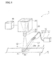
- Figure 1 is a conceptional schematic diagram of a discrimination system which includes an embodiment of image data analyzing equipment relating to the present invention.
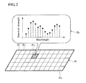
- Figure 2 is a conceptional schematic diagram for explaining a hyperspectral image.
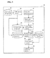
- Figure 3 is a block diagram showing the compositions of image data analyzing equipment relating to an embodiment of the present invention.
- Figure 4 is a flow chart of a method of learning done prior to discrimination using SVM in the image data analyzing equipment relating to an embodiment of the present invention.
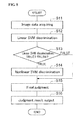
- Figure 5 is a flow chart showing how an image data is analyzed in an embodiment of image data analyzing equipment relating to the present invention.
- Figure 6A is a photograph showing a result of intermediate discrimination of Example 1 in which the linear SVM was adopted
- Fig. 6B is a photograph showing a result of final discrimination of Example 1 in which the nonlinear SVM was adopted.
- Figure 7 is a photograph showing a discrimination result of Comparative example 1.
- FIG. 1 is a conceptional schematic diagram of a discrimination system which includes an embodiment of image data analyzing equipment relating to the present invention.
- a discrimination system 1 is equipment for inspecting whether any abnormality such as degeneration of inspection objects 3 (In Fig. 1 , a position where the inspection objects are placed is shown) exists or any foreign substance mixes with the inspection objects 3, which are dispersedly placed on a belt conveyor 2.
- inspection objects 3 are raw materials or products of foods or pharmaceuticals.
- foreign substances which adhere to inspection objects 3 include things such as hair which come from a living body, metals originating from manufacturing equipment, and contaminants.
- the degeneration of inspection objects 3 can be detected by measuring the amount of moisture, sugar, and the like which are contained in the inspection objects 3.
- the discrimination system 1 measures the spectrum of diffuse reflection light obtained by irradiating measurement light to inspection objects 3, and based on the spectrum, it detects abnormalities such as degeneration of the inspection objects 3, foreign substances adhering to the inspection object 3, and the like.
- the discrimination system 1. is equipped with a lamp unit 10, a detection unit 20, and an analyzing unit 30 (image data analyzing equipment).
- the lamp unit 10 irradiates measurement light having a given wavelength band to an illuminated region A 1 on a belt conveyor 2.
- the wavelength range of the measurement light irradiated by the lamp unit 10 is chosen as needed according to an inspection object 3 itself or an abnormality that is a detectable target such as degeneration of an inspection object 3 or a foreign substance adhering to an inspection object 3.
- near-infrared light specifically, light having a wavelength range of 800 nm to 2500 nm can suitably be used, but visible light instead of near-infrared light can also be used as the measurement light.
- a lamp unit 10 including a light source 11 (SC light source) for generating supercontinuum (SC) light.
- SC light source supercontinuum
- An illuminated region A1 is a region that is a part of the surface (loading surface 2b) of the belt conveyor 2 on which inspection objects 3 are placed.
- the illuminated region A1 spreads in the width direction (x-axis direction) which is perpendicular to a forward direction (y-axis direction) of the loading surface 2b and extends linearly from one end to the other end of the loading surface 2b.
- the width of the illuminated region A1 in the direction (y-axis direction) perpendicular to the extending direction is 10 mm or less.
- the lamp unit 10 has a light source 11, an illuminating section 12, and an optical fiber 13 for connection from the light source 11 to the illuminating section 12.
- the light source 11 generates SC light as near-infrared light. More specifically, the light source 11 that is a SC light source has a seed light source and a nonlinear medium such that light emitted from the seed light source is input into the nonlinear medium so that the spectrum thereof is expanded to a broad bandwidth by nonlinear optical effect in the nonlinear medium so as to output SC light.
- the near-infrared light (SC light) thus generated is incident on one of the end faces of the optical fiber 13.
- the near-infrared light travels through the core of the optical fiber 13 and is emitted from the other end face to the illuminating section 12.
- the illuminating section 12 irradiates the near-infrared light (SC light) emitted from the end face of the optical fiber 13 to the illuminated region A1 where inspection objects 3 are to be placed.
- a cylindrical lens is suitably used as the illuminating section 12 for emitting near-infrared light in a one-dimensional linear form corresponding to the illuminated region A1.
- the near-in.frared light L 1 that has been shaped into a linear form in the illuminating section 12 is irradiated therefrom to the illuminated region A1.
- the near-infrared light L1 output from the lamp unit 10 is reflected in a diffused manner at the inspection objects 3 placed on the illuminated region A1. Then, a part of the reflected light is incident on the detection unit 20 as diffuse reflection light L2.
- the detection unit 20 has a function as a hyperspectral sensor for acquiring a hyperspectral image.
- Figure 2 is a conceptional schematic diagram for explaining a hyperspectral image.
- the hyperspectral image is an image consisting of N-number of pixels P1 to PN, and one pixel Pn of them includes a spectral information Sn consisting of a plurality of intensity data.
- Each intensity data is a data showing the spectral strength at a specific wavelength (or a wavelength band), and Fig. 2 shows that 15 intensity data are held as the spectral information Sn in the pixel Pn.
- the hyperspectral image has a plurality of intensity data at each of the pixels constituting an image, and hence is a data consisting of three-dimensional composition: two-dimensional image element plus spectral data element.
- a hyperspectral image is an image that consists of pixels each having intensity data for at least five wavelength bands.
- the detection unit 20 has a slit 21, a spectrometer 22, and an OE converting section 23.
- the detection unit 20 has a view region 20s extending in the direction (x-axis direction) that is perpendicular to the forward direction 2a of the belt conveyor 2.
- the view region 20s of the detection unit 20 is a linear region which is included in the illuminated region A1 of the loading surface 2b and the diffuse reflection light L2 reflected from the view region 20s passes through the slit 21 and forms an image on the OE converted section.
- the slit 21 has an opening having a longer side in the direction parallel to the extending direction (x-axis direction) of the illuminated region A1.
- the diffuse reflection light L2 having been incident into the slit 21 of the detection unit 20 is incident on the spectrometer 22.
- the spectrometer 22 splits the diffuse reflection light L2 in the direction (y-axis direction) perpendicular to the longitudinal direction of the slit 21,i.e. the extending direction of the illuminated region A1.
- the light thus split by the spectrometer 22 is received by the OE converting section 23.
- the OE converting section 23 has a light-receiving face on which a plurality of photodetectors are two-dimensionally arranged, and the photodetectors respectively receive light.
- the OE converting section 23 receives light with the respective wavelengths of diffuse reflection light L2 reflected at the respective position along the width direction (x-axis direction) on the belt conveyor 2.
- each photodetector outputs a signal as information of a point on a two-dimensional plane regarding position and wavelength.
- the signals output from the photodetectors of the OE converting section 23 are sent, from the detection unit 20 to the analyzing unit 30, as image data relating to a hyperspectral image.
- the analyzing unit 30 analyzes the image data by using support vector machines (SVM).
- SVM support vector machines
- the hyperspectral image is an image data including the intensity data of at least five wavelength bands at every pixel, and wavelength bands are chosen so that a substance as a detection object can be identified for discrimination.
- wavelength bands are chosen such that a specific absorption peak deriving from the foreign substance is included therein.
- wavelength bands should be chosen to cover wavelengths of 1500 nm or 2100 nm, including vicinity of at least 100 nm thereof, since an absorption peak for sugar exists around those wavelengths. (From the position and strength of a peak originated from sugar, it is possible to find the kind and the contained quantity of the sugar, and hence to detect any abnormality of inspection objects 3 or evaluate the quality thereof.)
- SVM there are two kinds: linear SVM in which the discrimination boundary is expressed with a linear function of feature quantity and nonlinear SVM in which the discrimination boundary is expressed with a nonlinear function of feature quantity. Discrimination using the linear SVM is easy to apply to a real-time processing since the calculation quantity is small, although the precision is inferior, as compared with the nonlinear SVM. On the other hand, discrimination using the nonlinear SVM is superior in precision as compared with the linear SVM, but the calculation quantity thereof tends to increase as the precision of discrimination is improved by parameter adjustment. As described in more detail later, the analyzing unit 30 of the present embodiment enables high-precision and high-speed discrimination by using both the linear SVM and the nonlinear SVM.
- the analyzing unit 30 is a computer which includes hardware such as CPU (Central Processing Unit), RAM (Random Access Memory) which is a main storage, and ROM (Read Only Memory), a communication module for communication with other equipment such as a detection unit, and a hard disk for auxiliary storage. The operation of these components enables a function as the analyzing unit 30.
- CPU Central Processing Unit
- RAM Random Access Memory
- ROM Read Only Memory
- the operation of these components enables a function as the analyzing unit 30.
- FIG. 3 is a block diagram showing the compositions of the analyzing unit 30.
- the analyzing unit 30 includes a learning data storage part 31 for storing a learning image data, an SVM learning section 32, a first parameter storage part 33 for storing a linear SVM discrimination parameter, a second parameter storage part 34 for storing a nonlinear SVM discrimination parameter, an image data acquiring section 41, an image data processing part 47 (image data processing means), a linear SVM discriminating section 42 (linear SVM discrimination means), a nonlinear SVM discriminating section 43 (nonlinear SVM discrimination means), a discrimination result storage section 44 (storage means), a final judging section 45 (judging means), and a judgment result outputting section 46.
- the learning data storage part 31, the SVM learning section 32, the first parameter storage part 33, and the second parameter storage part 34 function to form and store parameters for discriminating a detection object contained in inspection objects 3.
- the image data acquiring section 41, the image data processing part 47, the linear SVM discriminating section 42, the nonlinear SVM discriminating section 43, the discrimination result storage section 44, the final judging section 45, and the judgment result outputting section 46 altogether function to analyze image data obtained from the inspection objects 3.
- image data of an inspection object 3 and a detection object are stored as image data about which the SVM of the analyzing unit 30 can learn.
- the analyzing unit 30 stores image data of beans and image data of hair (detection object).
- the image data to be analyzed by the analyzing unit 30 is a hyperspectral image as in the present embodiment, a similar hyperspectral image is used as a data for learning.
- the SVM learning section 32 recognizes, as object data, intensity data contained in pixels of an image captured from one of the detection objects, and calculates a discrimination boundary (linear SVM discrimination parameter and nonlinear SVM discrimination parameter) for judging whether or not the intensity data correspond to the object data.
- a discrimination boundary linear SVM discrimination parameter and nonlinear SVM discrimination parameter
- such two objects to be discriminated are beans and hair, and an intensity data contained in a pixel of an image obtained from hair is an "object data".
- this processing is performed such that an operator of the analyzing unit 30 specifies the image data of two objects to be discriminated, and orders the SVM learning section 32 to calculate a discrimination boundary by using as a feature quantity the intensity data which constitute spectral information for respective images of the two objects.
- the linear SVM discrimination parameter prepared by the SVM learning section 32 is stored in a first parameter storing section 33.
- the nonlinear SVM discrimination parameter is stored in a second parameter storing section 34.
- the linear SVM discrimination parameter and the nonlinear SVM discrimination parameter which are formed by the SVM learning section 32, can be formed such that their discrimination, precision is changed based on the instruction of the operator.
- This discrimination precision can appropriately be changed according to the number of times of analysis conducted using SVM and the kind of information to be acquired as a result of the analysis.
- the linear SVM is inferior in discrimination precision, but advantageous as compared to the nonlinear SVM because the linear SVM requires small calculation quantity for discrimination processing. Therefore, in the present embodiment, it is intended that a prior filtering is performed using the linear SVM so that the discrimination using the nonlinear SVM may not be performed with respect to pixels for which the possibility of a detection object (hair) is made extremely small by such filtering. Therefore, for the purpose of parameter used for the linear SVM discrimination, a parameter of rougher precision is formed so that a pixel in which a detection object is captured will not fall outside the target of discrimination using the nonlinear SVM.
- the image data acquiring section 41 has a function of acquiring image data from the detection unit 20.
- the image data acquired by the image data acquiring section 41 is an image data relating to a hyperspectral image captured from the above-mentioned inspection objects 3. If necessary, the image data acquired by the image data acquiring section 41 is sent to the linear SVM discriminating section 42 via the image data processing part 47.
- the image data processing part 47 which is not indispensable in the image data analyzing equipment of the present invention, processes the image data acquired in the image data acquiring section 41.
- data processing is, for example, a processing to normalize an intensity data which the image data holds in each pixel or a numerical processing to find differences between neighboring data.
- the analyzing unit 30 is enabled to perform analysis more efficiently.
- the linear SVM discriminating section 42 has a function of discriminating every pixel, depending on whether or not an intensity data therein is an object data (data indicating a detection object) as determined by using the linear SVM and using the intensity data (which is included in the image data) as feature quantity.
- the discrimination as to whether the intensity data is an object data or not is performed for every pixel by using the linear SVM discrimination parameter stored in the first parameter storage part 33.
- the information for identifying the pixel and the intensity data of the pixel are sent to the nonlinear SVM discriminating section 43.
- the information for identifying the pixel and the discrimination result are sent to the final judging section 45.
- the nonlinear SVM discriminating section 43 has a function of discriminating each pixel as to whether the intensity data thereof is an object data or not by using the nonlinear SVM and using the intensity data sent from the linear SVM discriminating section 42.
- the discrimination as to whether an intensity data is an object data or not is performed using the nonlinear SVM discrimination parameter stored in the second parameter storage part 34.
- the results of the discrimination made by the nonlinear SVM discriminating section 43 and the corresponding information for specifying the respective pixels are altogether sent to the discrimination result storage section 44. Also, as for a pixel for which the intensity data is judged not to be an object data by the nonlinear SVM discriminating section 43, the results of the discrimination made by the nonlinear SVM discriminating section 43 and the information for specifying the pixels are sent to the final judging section 45.
- the discrimination result storage section 44 has a function of storing the results of discrimination done by the nonlinear SVM discriminating section 43 and the corresponding information for specifying the respective pixels.
- the information stored in the discrimination result storage section 44 is used at the time of judgment by the final judging section 45.
- the function of the final judging section 45 is as follows: by referring to discrimination results and information for specifying the related pixels, which are sent from the linear SVM discriminating section 42 and the nonlinear SVM discriminating section 43, and by referring to discrimination results stored in the discrimination result storage section 44, of a plurality of pixels in an image data, if the number of specific pixels for which the nonlinear SVM discriminating section 43 determines the intensity data to be an object data is equal to or more than a predetermined number, then the final judging section 45 concludes that a detection object exists in a region constituted of the plurality of pixels including the specific pixels.
- the intensity data is discriminated as being an object data in a plurality of neighboring pixels by the nonlinear SVM discriminating section 43.
- an intensity data due to a noise which has accidentally occurred at the time of capturing an image data might be discriminated as being an object data. In such case, however, it is assumed that the possibility of a similar result being obtained in the neighboring pixels would be low.
- the final judging section 45 therefore, in a region having 25 pixels (5 pixels x 5 pixels), for example, if three or more pixels which are discriminated as pixels whose intensity data are object data and which capture an image of a detection object exist as a group, then the region is judged to be a region where the detection object has been captured. This will reduce such possibility as an intensity data due to a noise occurring accidentally in the image data might be discriminated as an object data, and accordingly, the analysis of an image data can be accomplished with higher precision.
- the above-mentioned method of judgment by the final judging section 45 is an exceedingly simplified example, and a more complicated judgment algorithm capable of high discrimination may be incorporated.
- the results of the judgment made by the final judging section 45 are sent to the judgment result outputting section 46.
- the judgment result outputting section 46 functions to notify the operator of a discrimination system I by outputting a result of judgment made by the final judging section 45.
- the manner of such output is, for example, an output to a monitor connected to the analyzing unit 30, or an output to a printer.
- For outputting judgment results there are various possible manners; for example, such output may be done as a two-dimensional image using the image data obtained by the detection unit 20.
- FIG. 4 is a flow chart of a method of learning done in the image data analyzing unit 30 prior to discrimination using SVM.
- learning is done in the SVM learning section 32, and a linear SVM discrimination parameter and a nonlinear SVM discrimination parameter are formed (SO1).
- the linear SVM discrimination parameter and the nonlinear SVM discrimination parameter are stored in the first parameter storage part 33 and the second parameter storage part 34, respectively (S02).
- S02 the pre-processing for analyzing image data is completed.
- the above-mentioned learning may be performed at any time prior to image data analysis. That is, numerous kinds of parameters may be formed at a time beforehand, or learning may be done immediately before the image data analysis.
- FIG. 5 is a flow chart showing how an image data is analyzed in the image data analyzing unit 30.
- Image data of imaging the inspection objects 3 are acquired by the image data acquiring section 41 of the analyzing unit 30 (S11, Image data acquiring step).
- the linear SVM discriminating section 42 performs discrimination by means of the linear SVM for every pixel (S12, Linear SVM discrimination step).
- the discrimination by means of the linear SVM is performed for all pixels contained in the image data, and depending on the results of such discrimination, judgment as to whether an intensity data is an object data (TRUE) or not (FALSE) is done for every pixel (S13, Linear SVM discrimination results judgment step).
- the discrimination results of pixels in which the intensity data are judged not to be object data are sent to the final judging section 45.
- the intensity data are sent to the nonlinear SVM discriminating section 43.
- the final judging section 45 of a plurality of pixels which includes specific pixels, if the number of pixels which the nonlinear SVM discriminating section 43 discriminates as the intensity data are object data is equal to or more than a given number, then it is concluded that a detection object exists in the region which is constituted of the plurality of pixels including the specific pixels. Then, the results of such judgment made by the final judging section 45 are sent to the judgment result outputting section 46, so that the results are output (S16, Output step).
- the above-described steps complete a series of processing relating to the image data analysis by the analyzing unit 30.
- the analyzing unit 30 image data analyzing equipment
- the image data analyzing method relating to the present embodiment discrimination using the linear SVM that enables high-speed processing that requires small calculation quantity is done beforehand, and then discrimination using the nonlinear SVM capable of high-precision discrimination that requires large calculation quantity is done with respect to the pixels which have been discriminated as the intensity data are object data as a result of the previous discrimination using the linear SVM. Therefore, as compared with the case where discrimination is conducted only with the linear SVM for all pixels, the discrimination can be performed with higher precision, and also as compared with the case where the discrimination is conducted only with the nonlinear SVM for all pixels, the discrimination can be accomplished at higher speed.
- the present invention enables high-precision and high speed analysis of image data.
- the analyzing unit 30 is equipped with the final judging section 45 having the fol lowing function: of a plurality of pixels including specific pixels in an image data, if the number of pixels discriminated by the nonlinear SVM discriminating section 43 judging the intensity data to be object data is equal to or more than a given number in the specific pixels, then the final judging section 45 concludes that a detection object exists in the region constituted of the plurality of pixels. Therefore, the possibility of false discrimination will be decreased: for example, in an image data an intensity data derived from a noise having accidentally occurred would rarely be judged to be an object data, and accordingly analysis of image data can be achieved with higher precision.
- the present invention is not limited to the embodiments described above, and the embodiments of the invention can be modified in various ways.
- the image data analyzing equipment relating to the present invention can be incorporated into a system for analyzing abnormality of other industrial products or observing an affected region of bio-tissue.
- the analyzing unit 30 is not always required to be connected with the detection unit 20 for capturing image data as in the above embodiments, and can be used by itself alone.
- the embodiments of the invention may be modified such that the discrimination is performed using a plurality of mutually different parameters for the linear SVM discriminating section 42 and the nonlinear SVM discriminating section 43, respectively.
- the embodiments may be modified such that judgment as to whether an intensity data is an object data or not (either TRUE or FALSE) is done by combining discrimination results obtained using a plurality of parameters. More specifically, for example, it is possible to structure such that in the linear SVM discriminating section 42, discrimination is performed by means of the linear SVM using three kinds of mutually different parameters, and in the nonlinear SVM discriminating section 43, discrimination is performed by means of the linear SVM using two kinds of mutually different parameters.
- one of possible methods is such that if all judgments in the discriminations by three kinds of linear SVM are "TRUE" in the linear SVM discriminating section 42, the results of the discrimination made in the linear SVM discriminating section 42 are regarded as object data, whereas in the nonlinear SVM discriminating section 43, if the judgment in either one of the two kinds of nonlinear SVM is "TRUE", the results of the discrimination by the nonlinear SVM discriminating section 43 are regarded as object data.
- the final judging section 45 is described with respect to embodiments in which the last judgment is conducted considering the results of discrimination for a plurality of neighboring pixels; however, an embodiment may be adopted such that judgment in the final judging section 45 is conducted solely on the basis of the results of the discrimination made for every pixel by the nonlinear SVM discriminating section 43.
- the final judging section 45 of the analyzing unit 30 on the basis of discrimination results obtained using the nonlinear SVM. judgment was done as to whether an intensity data was an object data or not, and no judgment was made on the basis of the discrimination results for a plurality of neighboring pixels.
- the linear SVM discrimination parameter that was used when performing discrimination by the linear SVM, a low standard to recognize an object data was set so that the intensity data of a pixel which imaged a hair might be recognized correctly as an object data in the image data.
- the nonlinear SVM discrimination parameter was set to have a value that would enable correct discrimination of the pixel which imaged a hair.
- the analysis of the image data used in Example I was performed by using only the linear SVM.
- the analysis target was all pixels constituting the image data, and a linear SVM discrimination parameter adopted for the linear SVM of comparative example 1 is different from the linear SVM discrimination parameter adopted for the linear SVM of the Example 1 and a high standard to recognize an object data was set to decrease a false detection.
- Example 1 The analysis of the image data used in Example 1 was performed by using only the nonlinear SVM.
- the analysis target was all pixels constituting the image data, and the analysis was done using a nonlinear SVM discrimination parameter enabling correct discrimination of a pixel that imaged a hair.
- Figure 6A is a photograph showing an intermediate result of discrimination done using the linear SVM in Example 1
- Fig. 6B is a photograph showing the last result of the discrimination made using the nonlinear SVM in Example 1.
- Figure 7 is a photograph showing the result of the analysis done in Comparative example 1. In all of these photographs, pixels which were discriminated by recognizing the intensity data as object data (that is, hair) are shown in white, and pixels which were discriminated by recognizing the intensity data to be not object data is shown in black or gray.
- Example 1 and Comparative examples I and 2 The precision of detection and the processing time by the analysis in Example 1 and Comparative examples I and 2 were evaluated.
- Table I shows the percentage of detecting the detection objects (hair), the percentage of false detection, and the processing time (from the beginning to the end of analysis) by the analysis in Example 1 and Comparative examples 1 and 2.
- Table 1 Example 1 Comparative example 1 Comparative example 2 Detection percentage(%) 96.8 58.4 96.8 False-detection percentage (%) 0.02 0.11 0.03 Processing time (second) 0.9 0.5 85.7
- Detection percentage is a ratio of the number of hairs actually detected to the number of hairs which mixed into bean products on the processing line. The detection percentage indicates that the higher the percentage, the more hairs can be detected.
- the term “false-detection percentage” means a ratio of pixels which were judged to be “TRUE”, that is, a ratio of the number of pixels which were judged to include detection objects, i.e., hair) in the case where discrimination was done with respect to a hyperspectral image of 1,000,000 pixels obtained by photographing a processing line on which no hair existed. The false-detection ratio indicates that the smaller the ratio, the smaller the decrease in yield of the processing line.
- the "processing time” is an average time that was spent for discrimination of the whole hyperspectral image.
Landscapes
- Engineering & Computer Science (AREA)
- Physics & Mathematics (AREA)
- Theoretical Computer Science (AREA)
- General Physics & Mathematics (AREA)
- Multimedia (AREA)
- General Health & Medical Sciences (AREA)
- Immunology (AREA)
- Chemical & Material Sciences (AREA)
- Analytical Chemistry (AREA)
- Biochemistry (AREA)
- Health & Medical Sciences (AREA)
- Spectroscopy & Molecular Physics (AREA)
- Life Sciences & Earth Sciences (AREA)
- Pathology (AREA)
- Mathematical Physics (AREA)
- Computer Vision & Pattern Recognition (AREA)
- Investigating Or Analysing Materials By Optical Means (AREA)
- Photometry And Measurement Of Optical Pulse Characteristics (AREA)
- Investigating Materials By The Use Of Optical Means Adapted For Particular Applications (AREA)
- Image Analysis (AREA)
Applications Claiming Priority (1)
| Application Number | Priority Date | Filing Date | Title |
|---|---|---|---|
| JP2010002906A JP2011141809A (ja) | 2010-01-08 | 2010-01-08 | 画像データ分析装置及び画像データ分析方法 |
Publications (2)
| Publication Number | Publication Date |
|---|---|
| EP2343671A2 true EP2343671A2 (fr) | 2011-07-13 |
| EP2343671A3 EP2343671A3 (fr) | 2013-11-27 |
Family
ID=43829331
Family Applications (1)
| Application Number | Title | Priority Date | Filing Date |
|---|---|---|---|
| EP10197258.6A Withdrawn EP2343671A3 (fr) | 2010-01-08 | 2010-12-29 | Équipement et procédé d'analyse de données d'images |
Country Status (4)
| Country | Link |
|---|---|
| US (1) | US20110170783A1 (fr) |
| EP (1) | EP2343671A3 (fr) |
| JP (1) | JP2011141809A (fr) |
| AU (1) | AU2011200034A1 (fr) |
Cited By (3)
| Publication number | Priority date | Publication date | Assignee | Title |
|---|---|---|---|---|
| CN102507462A (zh) * | 2011-11-08 | 2012-06-20 | 浙江大学 | 一种基于高光谱分析的铜品质检测方法及其检测系统 |
| CN102788794A (zh) * | 2012-07-30 | 2012-11-21 | 江苏大学 | 基于多传感信息融合的叶菜类蔬菜叶片农药残留检测装置及方法 |
| CN110414438A (zh) * | 2019-07-30 | 2019-11-05 | 西南交通大学 | 基于空间聚类信息修正的高光谱图像识别方法 |
Families Citing this family (9)
| Publication number | Priority date | Publication date | Assignee | Title |
|---|---|---|---|---|
| JP5772420B2 (ja) * | 2011-09-09 | 2015-09-02 | 住友電気工業株式会社 | 特徴量抽出装置、対象物検出システム、コンピュータプログラム及び特徴量抽出方法 |
| JP2013137225A (ja) * | 2011-12-28 | 2013-07-11 | Sumitomo Electric Ind Ltd | 対象検出装置および対象検出方法 |
| JP6144915B2 (ja) * | 2012-01-30 | 2017-06-07 | キヤノン株式会社 | 生体組織画像の再構成方法、取得方法及び装置 |
| US9213892B2 (en) * | 2012-12-21 | 2015-12-15 | Honda Motor Co., Ltd. | Real-time bicyclist detection with synthetic training data |
| JP6235886B2 (ja) * | 2013-01-08 | 2017-11-22 | キヤノン株式会社 | 生体組織画像の再構成方法及び装置並びに該生体組織画像を用いた画像表示装置 |
| JP7185388B2 (ja) * | 2016-11-21 | 2022-12-07 | 日東電工株式会社 | 検査装置及び検査方法 |
| CN109472199B (zh) * | 2018-09-29 | 2022-02-22 | 深圳大学 | 一种图像融合分类的方法及装置 |
| JP7811739B2 (ja) * | 2021-01-26 | 2026-02-06 | パナソニックIpマネジメント株式会社 | 検査対象に含まれる異物を検出する方法および装置 |
| JPWO2022176686A1 (fr) * | 2021-02-22 | 2022-08-25 |
Citations (1)
| Publication number | Priority date | Publication date | Assignee | Title |
|---|---|---|---|---|
| JP2007505733A (ja) | 2003-09-20 | 2007-03-15 | キネテイツク・リミテツド | 廃棄物の流れ中の目標物を分類する装置および方法 |
Family Cites Families (5)
| Publication number | Priority date | Publication date | Assignee | Title |
|---|---|---|---|---|
| JPS6016673B2 (ja) * | 1978-12-25 | 1985-04-26 | 川崎重工業株式会社 | サ−ボ系における被検体認識装置 |
| JP2003123076A (ja) * | 2001-10-17 | 2003-04-25 | Ricoh Co Ltd | 画像処理装置及び画像処理プログラム |
| JP2006048322A (ja) * | 2004-08-04 | 2006-02-16 | Seiko Epson Corp | オブジェクト画像検出装置、顔画像検出プログラムおよび顔画像検出方法 |
| JP4654208B2 (ja) * | 2007-02-13 | 2011-03-16 | 日立オートモティブシステムズ株式会社 | 車載用走行環境認識装置 |
| US8045798B2 (en) * | 2007-08-30 | 2011-10-25 | Xerox Corporation | Features generation and spotting methods and systems using same |
-
2010
- 2010-01-08 JP JP2010002906A patent/JP2011141809A/ja active Pending
- 2010-12-29 EP EP10197258.6A patent/EP2343671A3/fr not_active Withdrawn
-
2011
- 2011-01-04 AU AU2011200034A patent/AU2011200034A1/en not_active Abandoned
- 2011-01-05 US US12/984,743 patent/US20110170783A1/en not_active Abandoned
Patent Citations (1)
| Publication number | Priority date | Publication date | Assignee | Title |
|---|---|---|---|---|
| JP2007505733A (ja) | 2003-09-20 | 2007-03-15 | キネテイツク・リミテツド | 廃棄物の流れ中の目標物を分類する装置および方法 |
Cited By (3)
| Publication number | Priority date | Publication date | Assignee | Title |
|---|---|---|---|---|
| CN102507462A (zh) * | 2011-11-08 | 2012-06-20 | 浙江大学 | 一种基于高光谱分析的铜品质检测方法及其检测系统 |
| CN102788794A (zh) * | 2012-07-30 | 2012-11-21 | 江苏大学 | 基于多传感信息融合的叶菜类蔬菜叶片农药残留检测装置及方法 |
| CN110414438A (zh) * | 2019-07-30 | 2019-11-05 | 西南交通大学 | 基于空间聚类信息修正的高光谱图像识别方法 |
Also Published As
| Publication number | Publication date |
|---|---|
| US20110170783A1 (en) | 2011-07-14 |
| AU2011200034A1 (en) | 2011-07-28 |
| JP2011141809A (ja) | 2011-07-21 |
| EP2343671A3 (fr) | 2013-11-27 |
Similar Documents
| Publication | Publication Date | Title |
|---|---|---|
| EP2343671A2 (fr) | Équipement et procédé d'analyse de données d'images | |
| JP5206335B2 (ja) | 主成分分析方法、主成分分析装置、異種品検出装置、主成分分析プログラム、及び、主成分分析プログラムが記録された記録媒体 | |
| US20140319351A1 (en) | Inspection apparatus and an inspection method | |
| EP2943761B1 (fr) | Système et procédés d'imagerie multispectrale plein champ | |
| US9164029B2 (en) | Method of classifying and discerning wooden materials | |
| JP2012098181A (ja) | 検出装置及び検出方法 | |
| CN107064096A (zh) | 基于高光谱成像的混合物粉末无损定量检测装置及方法 | |
| JP2010169484A5 (fr) | ||
| KR102240757B1 (ko) | Lctf-기반 다분광 영상 기술을 이용한 가공 채소류 내 포함된 이물질 실시간 검출 시스템 | |
| US20170254741A1 (en) | Quality evaluation method and quality evaluation device | |
| US10126709B2 (en) | Apparatus and method for performing in-line lens-free digital holography of an object | |
| EP2081013A1 (fr) | Méthode d'analyse d'articles alimentaires et dispositif associé | |
| JP2015203586A (ja) | 検査方法 | |
| JP2012189390A (ja) | 毛髪検出装置 | |
| US20240369815A1 (en) | Apparatus and method for coaxial line-scanning brillouin microscopy | |
| US20050239117A1 (en) | Biochip measuring method and biochip measuring apparatus | |
| JP2016090476A (ja) | 異物検出方法 | |
| JP5298684B2 (ja) | 異物の検出装置及び検出方法 | |
| EP2081012A1 (fr) | Méthode d'analyse d'articles alimentaires et dispositif associé | |
| CN111879789A (zh) | 金属表面缺陷检测方法及系统 | |
| JP2015040818A (ja) | 穀物分類方法及び穀物分類装置 | |
| JP2018205084A (ja) | 光学測定装置及び光学測定方法 | |
| EP3588434B1 (fr) | Systèmes et procédés d'analyse d'un article en tissu | |
| JP2006317261A (ja) | 走査型サイトメータの画像処理方法及び装置 | |
| Quintana et al. | Instrumentation Evaluation for Hyperspectral Microscopy Targeting Enhanced Medical Histology |
Legal Events
| Date | Code | Title | Description |
|---|---|---|---|
| PUAI | Public reference made under article 153(3) epc to a published international application that has entered the european phase |
Free format text: ORIGINAL CODE: 0009012 |
|
| AK | Designated contracting states |
Kind code of ref document: A2 Designated state(s): AL AT BE BG CH CY CZ DE DK EE ES FI FR GB GR HR HU IE IS IT LI LT LU LV MC MK MT NL NO PL PT RO RS SE SI SK SM TR |
|
| AX | Request for extension of the european patent |
Extension state: BA ME |
|
| PUAL | Search report despatched |
Free format text: ORIGINAL CODE: 0009013 |
|
| AK | Designated contracting states |
Kind code of ref document: A3 Designated state(s): AL AT BE BG CH CY CZ DE DK EE ES FI FR GB GR HR HU IE IS IT LI LT LU LV MC MK MT NL NO PL PT RO RS SE SI SK SM TR |
|
| AX | Request for extension of the european patent |
Extension state: BA ME |
|
| RIC1 | Information provided on ipc code assigned before grant |
Ipc: G01N 21/27 20060101ALI20131023BHEP Ipc: G06K 9/00 20060101ALI20131023BHEP Ipc: G06K 9/68 20060101ALI20131023BHEP Ipc: G06K 9/62 20060101ALI20131023BHEP Ipc: G06K 9/20 20060101ALI20131023BHEP Ipc: G06T 7/00 20060101ALI20131023BHEP Ipc: G06K 9/46 20060101AFI20131023BHEP |
|
| STAA | Information on the status of an ep patent application or granted ep patent |
Free format text: STATUS: THE APPLICATION IS DEEMED TO BE WITHDRAWN |
|
| 18D | Application deemed to be withdrawn |
Effective date: 20140528 |