EP2343704A2 - Vorrichtung und Verfahren zur Schichtsprungsteuerung in einem optischen Plattenlaufwerk - Google Patents
Vorrichtung und Verfahren zur Schichtsprungsteuerung in einem optischen Plattenlaufwerk Download PDFInfo
- Publication number
- EP2343704A2 EP2343704A2 EP11000024A EP11000024A EP2343704A2 EP 2343704 A2 EP2343704 A2 EP 2343704A2 EP 11000024 A EP11000024 A EP 11000024A EP 11000024 A EP11000024 A EP 11000024A EP 2343704 A2 EP2343704 A2 EP 2343704A2
- Authority
- EP
- European Patent Office
- Prior art keywords
- disc
- circumferential position
- optical disc
- predetermined circumferential
- layer jump
- Prior art date
- Legal status (The legal status is an assumption and is not a legal conclusion. Google has not performed a legal analysis and makes no representation as to the accuracy of the status listed.)
- Withdrawn
Links
Images


Classifications
-
- G—PHYSICS
- G11—INFORMATION STORAGE
- G11B—INFORMATION STORAGE BASED ON RELATIVE MOVEMENT BETWEEN RECORD CARRIER AND TRANSDUCER
- G11B7/00—Recording or reproducing by optical means, e.g. recording using a thermal beam of optical radiation by modifying optical properties or the physical structure, reproducing using an optical beam at lower power by sensing optical properties; Record carriers therefor
- G11B7/08—Disposition or mounting of heads or light sources relatively to record carriers
- G11B7/085—Disposition or mounting of heads or light sources relatively to record carriers with provision for moving the light beam into, or out of, its operative position or across tracks, otherwise than during the transducing operation, e.g. for adjustment or preliminary positioning or track change or selection
- G11B7/08505—Methods for track change, selection or preliminary positioning by moving the head
- G11B7/08511—Methods for track change, selection or preliminary positioning by moving the head with focus pull-in only
-
- B—PERFORMING OPERATIONS; TRANSPORTING
- B62—LAND VEHICLES FOR TRAVELLING OTHERWISE THAN ON RAILS
- B62H—CYCLE STANDS; SUPPORTS OR HOLDERS FOR PARKING OR STORING CYCLES; APPLIANCES PREVENTING OR INDICATING UNAUTHORIZED USE OR THEFT OF CYCLES; LOCKS INTEGRAL WITH CYCLES; DEVICES FOR LEARNING TO RIDE CYCLES
- B62H5/00—Appliances preventing or indicating unauthorised use or theft of cycles; Locks integral with cycles
- B62H5/08—Appliances preventing or indicating unauthorised use or theft of cycles; Locks integral with cycles preventing the drive
- B62H5/12—Appliances preventing or indicating unauthorised use or theft of cycles; Locks integral with cycles preventing the drive acting on the chain wheel or the chain
-
- G—PHYSICS
- G11—INFORMATION STORAGE
- G11B—INFORMATION STORAGE BASED ON RELATIVE MOVEMENT BETWEEN RECORD CARRIER AND TRANSDUCER
- G11B7/00—Recording or reproducing by optical means, e.g. recording using a thermal beam of optical radiation by modifying optical properties or the physical structure, reproducing using an optical beam at lower power by sensing optical properties; Record carriers therefor
- G11B2007/0003—Recording, reproducing or erasing systems characterised by the structure or type of the carrier
- G11B2007/0009—Recording, reproducing or erasing systems characterised by the structure or type of the carrier for carriers having data stored in three dimensions, e.g. volume storage
- G11B2007/0013—Recording, reproducing or erasing systems characterised by the structure or type of the carrier for carriers having data stored in three dimensions, e.g. volume storage for carriers having multiple discrete layers
Definitions
- This document relates to an apparatus and a method for controlling layer jump reliably in a multi-layer optical disc.
- Optical discs such as CD, DVD, and BD have come into wide use. Now a dual layer disc which has two recording layers and a multi-layer disc which has three or more recording layers are emerging.
- a focusing servomechanism which focuses a laser beam on a target recording layer in a rotating optical disc should be operated properly; to move to another recording layer form a current recording layer, layer jump operation of focusing a laser beam from the current recording layer to the corresponding recording layer should be carried out.
- a beam coming from a laser diode passes through an object lens and focuses toward the disc; a beam reflected from the disc is sensed by a photo detector, from which a focusing error signal, tracking error signal, and RF signal can be obtained.
- a focusing error signal is used to actuate a focusing actuator supporting the object lens, performed is the focusing servomechanism through which the laser beam is focused on a recording layer of a rotating disc with shaking motion; meanwhile, the focusing error signal generated around the recording layer is used to actuate a focusing actuator, thereby accomplishing layer jump operation.
- a disc usually shakes up and down/left and right while rotating; shaking up and down is called surface vibration while shaking left and right, eccentricity. If the disc suffers surface vibration, the recording layer rises above and falls below a reference height; therefore, performing layer jump reliably becomes difficult, eventually making the layer jump liable to error and delayed.
- An aspect of this document is to provide a method of performing layer jump operation reliably.
- a method for controlling layer jump according to one embodiment of the present invention comprises carrying out layer jump operation at a predetermined circumferential position in a rotating disc.
- the predetermined circumferential position can be detected based on a signal generated from a motor rotating the disc.
- the predetermined circumferential position can correspond to a position where displacement of a disc in up and down direction while the disc makes one rotation becomes largest and/or smallest.
- the method can further comprise detecting the predetermined circumferential position and storing the detected position in a memory; and upon request of layer jump, comparing a current circumferential position of a rotating disc with the predetermined circumferential position stored in the memory.
- the predetermined circumferential position can be detected based on a driving signal applied to a focusing actuator at an outer circumference of a disc while a focusing servo is turned on.
- the predetermined circumferential position can be detected when an optical disc drive recognizes that an optical disc inserted therein has two or more recording layers.
- a kick pulse and a break pulse to move an object lens up or down can be applied sequentially.
- level and width of each of the kick pulse and the break pulse and an interval between the two pulses are determined beforehand based on a distance between jumping layers.
- the distance between the layers can be calculated based on disc information of the optical disc or an interval of an S-curve which is generated as an optical disc drive swings an object lens to recognize an optical disc.
- An optical disc drive records data in an optical disc or reproduce data from the optical disc, comprising an optical pick-up comprising an actuator for moving an object lens up and down; a spindle motor for rotating an optical disc; a driving unit for driving the actuator and the spindle motor; a memory for storing data; a controller configured to compare a circumferential position of a rotating disc with a predetermined circumferential position stored in the memory based on a signal generated at the spindle motor upon request of layer jump and control and control the driving unit to perform layer jump operation at the predetermined circumferential position.
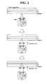
- FIG. 1 illustrates a focus servomechanism for a dual layer disc
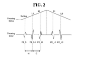
- FIG. 2 illustrates a focus drive signal and an error signal for a dual layer disc
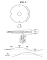
- FIG. 3 illustrates an example where a disc having a vibration component shakes up and down while rotating
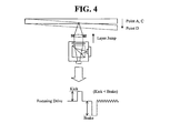
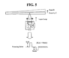
- FIGS. 4 and 5 illustrate a focusing drive signal for layer jump of a surface vibration disc
- FIG. 6 illustrates an embodiment of detecting FG addresses of a spindle motor at a time point where change of disc displacement in an up and down direction is smallest according to the present invention
- FIG. 7 illustrates a structure of an optical disc drive to which the present invention is applied.
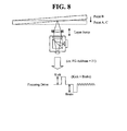
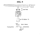
- FIGS. 8 and 9 illustrate an embodiment where layer jump operation is performed at a time point where change of disc displacement in an up and down direction is smallest according to the present invention.
- An optical pick-up (OPU) for recording and reproducing data to and from an optical disc in an optical disc drive comprises a focusing actuator for performing focusing servo and layer jump operation by moving an object lens in a vertical direction.
- focusing error signals FE_S, FE L0, FE_L1 in the shape of an S-curve are detected sequentially with a predetermined time interval t1, t2 near the surface, a first layer L0, and a second layer L1 of a dual layer disc.
- the optical disc drive to perform jump operation from the first layer L0 to the second layer L1, applies the focusing drive signal in a direction along which the focusing actuator is elevated; to perform jump operation from the second layer L1 to the first layer L0, in a direction along which the focusing actuator descends.
- the focusing drive signal driving the focusing actuator is applied to the focusing actuator with the same phase as the displacement of the disc recording layer in an up and down direction.
- the acceleration of the disc in an up and down direction becomes zero at B and D point where displacement of the disc is largest, while the absolute value of the acceleration thereof becomes largest at A and C point.
- the outer circumference of the disc is parallel to the inner circumference thereof when C point of the disc passes the optical pick-up, whereas the outer circumference of the disc descends when D point passes the optical pick-up. If layer up operation is performed in the opposite direction of displacement of the outer circumference of the disc at the time of the C point passing the optical pick-up and the D point moving toward the optical pick-up, to perform layer jump operation properly, in the focusing drive signal applied to the focusing actuator, magnitude (or amplitude) of a kick pulse to elevate the focusing actuator should be made smaller than that of a break pulse to stop the rising focusing actuator (kick ⁇ brake).
- the outer circumference of the disc is parallel to the inner circumference thereof when A point of the disc passes the optical pick-up, whereas the outer circumference of the disc ascends when B point passes the optical pick-up. If layer up operation is performed in the same direction of displacement of the outer circumference of the disc at the time of the A point passing the optical pick-up and the B point moving toward the optical pick-up, to perform layer jump operation properly, in the focusing drive signal applied to the focusing actuator, magnitude (or amplitude) of a kick pulse to elevate the focusing actuator should be made larger than that of a break pulse to stop the rising focusing actuator (kick > brake).
- the present invention by performing layer jump at the time or at the position of zero or small acceleration in an up and down direction of the disc, in other words, by performing layer jump at a predetermined circumferential position of the disc, allows reliable layer jump without adjusting the kick and the break pulses of the focusing drive signal for layer jump separately depending on situations.
- the focusing drive signal for layer jump can be applied at the position found.
- FIG. 6 illustrates an embodiment of detecting FG address of a spindle motor at a time point where change of disc displacement in an up and down direction is smallest according to the present invention.
- FG frequency generating
- the magnitude (for example, voltage value) of the focusing drive signal applied to the focusing actuator for focusing servo as the disc rotates is measured; by referring to the FG address output from the spindle motor, searched for is the FG address at the time point when the change of displacement in an up and down direction of the disc is smallest (or at the time point when the acceleration in an up and down direction of the disc is zero or small)---that is, the FG address when the magnitude of the focusing drive signal is largest and smallest---the FG address found can be stored in the memory.
- the magnitude of the focusing drive signal applied to the focusing actuator is largest in the ascending direction at point B and the magnitude of the focusing drive signal is largest in the descending direction at point D; the former corresponds to FG address 21 while the latter FG address 9.
- the kick pulse and the break pulse for layer jump can be applied sequentially to the focusing actuator at the time point (or with a little time difference before or after the time point) when an FG address from among FG addresses output from the spindle motor while the focusing servo is maintained corresponds to the FG address found from the memory.
- the present invention can be applied to a playback- only drive which only reproduces the data of an optical disc or various types of optical disc drives (ODDs) which can record data in an optical disc.
- ODDs optical disc drives
- FIG. 7 illustrates one embodiment of a structure of an optical disc drive to which the present invention is applied.
- an optical disc drive comprises a spindle motor 11; a sled motor 12; an optical pick-up 20 recording and reading out data to and from an optical disc by using a laser beam; a recording/playback unit driving the spindle motor 11, the sled motor 12, and the optical pick-up 20 and processing a servo signal and recording/playback data; and a controller 70 controlling the recording/playback unit.
- the recording/playback unit may comprise an optical driving unit 30, a digital signal processor (DSP) 40, an R/F unit 50, and a servo/driving unit60, where the optical driving unit 30 can be included in the optical pick-up 20.
- DSP digital signal processor
- the DSP 40 converts input digital data into a recording format by adding an error correction code (ECC); an optical driving unit 30 outputs a light quantity driving signal according to an input signal; the optical pick-up 20 records data to an optical disc 10 or reads data from a recording surface of the optical disc 10 according to the light quantity driving signal.
- ECC error correction code
- the R/F unit 50 outputs the signal detected at the optical pick-up 20 as a binary signal by filtering and shaping the detected signal; and also generates and outputs a tracking error signal TE, a focusing error signal FE, an RF signal, and so on.
- the DSP 40 by using a built-in clock synchronized with the binary signal, restores the binary signal to the original data.
- the servo/driving unit 60 generates a servo signal required for focusing servo, tracking servo, sled servo, and spindle servo based on the signal from the R/F unit 50; drives the spindle motor 11 which rotates the optical disc 10; drives the sled motor 12 which moves the optical pick-up 20 toward the inner and outer circumference of the optical disc 10; and drives a current required for focusing servo and tracking servo of an object lens within the optical pick-up 20.
- the controller 70 records or reads out data to and from an optical disc by controlling individual elements; to read out data from the optical disc 10 by controlling the optical driving unit 30, drives a laser diode within the optical pick-up 20 by using playback power; and to record data to the optical disc 10, drives the laser diode by recording power.
- the controller 70 based on an RF signal detected at the optical pick-up 20 and output from the R/F unit 50; and an FG signal generated from the spindle motor 11, controls the servo/driving unit 60 and drives the spindle motor 11, thereby rotating the optical disc 10 with a speed required, moves the optical pick-up 20 to a required position by driving the sled motor 12, and performs focusing servo and tracking servo by applying a current to an actuator supporting the object lens within the optical pick-up 20.
- the controller 70 rotates the optical disc by using the spindle motor 11 by controlling the servo/driving unit 60 and at the same time, moves the optical pick-up 20 by using the sled motor 12 to a predetermined outer circumferential area of the optical disc; at this time, FG addresses which the spindle motor 11 generates while rotating the disc are input.
- the controller 70 turns on the focusing servo by controlling the servo/driving unit 60 and detects the magnitude of a focusing drive signal applied to a focusing actuator while an optical disc makes one rotation; the controller 70 temporarily stores the voltage value of the focusing drive signal corresponding to each of the 24 FG addresses as the data value for each FG address; the controller 70 detects an FG address corresponding to the time point at which the voltage value of the largest focusing drive signal is applied and/or the voltage value of the smallest focusing drive signal is applied and stores the detected FG addresses in the memory 80.
- Such operation can be carried out every time a multi-layer disc is inserted in the optical disc drive or power is supplied to the optical disc drive or the optical disc drive is reset. In other words, the above operation can be carried out when the optical disc drive recognizes or determines an inserted optical disc; more specifically, the above operation is carried out when it is determined that the optical disc comprises two or more recording layers.
- the controller 70 if layer jump operation is requested during recording operation or playback operation about a multi-layer disc, turns off the focusing servo at the time point (or with a little time difference before or after the time point) when an FG address identical to the FG address stored in the memory 80 is counted while maintaining the focusing servo and carries out layer jump operation.
- the controller 70 controls the servo/driving unit 60; generates the kick pulse and the break pulse of the focusing drive signal for layer jump sequentially; and applies the generated pulses to the focusing actuator, where the kick pulse and the break pulse can have the same amplitude or magnitude.
- the controller 70 controls the servo/driving unit 60; generates the kick pulse and the break pulse of the focusing drive signal for layer jump sequentially; and applies the generated pulses to the focusing actuator.
- Magnitudes (levels) and widths of the kick pulse and the break pulses of the focusing drive signal for layer jump; and an interval between the two pulses can be stored in the memory 80 after being determined previously according to the type of the multi-layer disc; those values can be determined by disc type, number of layers, and the interval between the layers.
- each level and width of the kick pulse and the break pulse; and the interval between the two pulses can be stored in the memory 80 after being calculated previously according to the distance and direction (layer up or layer down) between layers where layer jump is to be performed.
- the interval between layers can be measured based on a time interval of an S-curve which is detected by swinging the focusing actuator up and down; magnitudes (levels) and widths of the kick pulse and the break pulse and the interval between the two pulses can be determined by the measured interval between the layers.
- the interval between layers can be calculated from the number of layers and the disc type which can be obtained from disc information recorded in a disc.
- the level and the width do not have to be the same for the kick pulse and the break pulse.
Landscapes
- Engineering & Computer Science (AREA)
- Mechanical Engineering (AREA)
- Moving Of The Head For Recording And Reproducing By Optical Means (AREA)
- Optical Recording Or Reproduction (AREA)
Applications Claiming Priority (1)
| Application Number | Priority Date | Filing Date | Title |
|---|---|---|---|
| KR1020100000298A KR20110080193A (ko) | 2010-01-05 | 2010-01-05 | 광디스크 드라이브에서의 레이어 점프 제어 장치 및 방법 |
Publications (2)
| Publication Number | Publication Date |
|---|---|
| EP2343704A2 true EP2343704A2 (de) | 2011-07-13 |
| EP2343704A3 EP2343704A3 (de) | 2012-03-07 |
Family
ID=43827340
Family Applications (1)
| Application Number | Title | Priority Date | Filing Date |
|---|---|---|---|
| EP11000024A Withdrawn EP2343704A3 (de) | 2010-01-05 | 2011-01-04 | Vorrichtung und Verfahren zur Schichtsprungsteuerung in einem optischen Plattenlaufwerk |
Country Status (4)
| Country | Link |
|---|---|
| US (1) | US20110164485A1 (de) |
| EP (1) | EP2343704A3 (de) |
| KR (1) | KR20110080193A (de) |
| CN (1) | CN102117627A (de) |
Family Cites Families (9)
| Publication number | Priority date | Publication date | Assignee | Title |
|---|---|---|---|---|
| JPH1097720A (ja) * | 1996-09-20 | 1998-04-14 | Nikon Corp | 情報記録再生装置 |
| JP3563239B2 (ja) * | 1997-07-10 | 2004-09-08 | パイオニア株式会社 | フォーカス制御装置 |
| JP3720203B2 (ja) * | 1998-11-17 | 2005-11-24 | パイオニア株式会社 | フォーカスジャンプ装置 |
| JP2001307341A (ja) * | 2000-04-24 | 2001-11-02 | Matsushita Electric Ind Co Ltd | 光ディスク装置 |
| CN1299271C (zh) * | 2001-07-26 | 2007-02-07 | 索尼株式会社 | 光盘记录/再现装置、其聚焦方法 |
| TWI253067B (en) * | 2004-06-15 | 2006-04-11 | Lite On It Corp | Intelligent layer jump method |
| KR20080010051A (ko) * | 2006-07-25 | 2008-01-30 | 삼성전자주식회사 | 광 디스크 드라이브 및 그 제어 방법 |
| US20100177608A1 (en) * | 2006-08-21 | 2010-07-15 | Hideo Morishita | Optical disc and method for controlling the same |
| KR20080018681A (ko) * | 2006-08-25 | 2008-02-28 | 삼성전자주식회사 | 최소 편향 가속도 지점 검출, 포커스 풀인 및 레이어 점프방법과 그와 같은 방법을 수행할 수 있는 광 디스크 구동기 |
-
2010
- 2010-01-05 KR KR1020100000298A patent/KR20110080193A/ko not_active Withdrawn
-
2011
- 2011-01-04 EP EP11000024A patent/EP2343704A3/de not_active Withdrawn
- 2011-01-04 US US12/984,211 patent/US20110164485A1/en not_active Abandoned
- 2011-01-05 CN CN2011100053132A patent/CN102117627A/zh active Pending
Non-Patent Citations (1)
| Title |
|---|
| None |
Also Published As
| Publication number | Publication date |
|---|---|
| KR20110080193A (ko) | 2011-07-13 |
| CN102117627A (zh) | 2011-07-06 |
| EP2343704A3 (de) | 2012-03-07 |
| US20110164485A1 (en) | 2011-07-07 |
Similar Documents
| Publication | Publication Date | Title |
|---|---|---|
| JP2002117534A (ja) | 光ディスク再生装置およびディスク種別判別方法 | |
| US8120998B2 (en) | Optical disk drive and method for driving the optical disk drive in relation to a velocity switching point | |
| EP2343704A2 (de) | Vorrichtung und Verfahren zur Schichtsprungsteuerung in einem optischen Plattenlaufwerk | |
| JP3938175B2 (ja) | 光ディスク記録再生装置 | |
| CN100380465C (zh) | 信息的记录装置及再现装置、信息的记录方法及再现方法 | |
| CN1981331A (zh) | 光盘记录再现装置及光盘记录再现装置的光盘判别方法 | |
| US7729221B2 (en) | Optical disk discrimination method and optical disk device | |
| US8174945B2 (en) | Multi-layered optical disk and optical disk device capable of addressing a focus lead-in operation | |
| US8189441B2 (en) | Method of recognizing track pitch of optical disk | |
| JP2011175701A (ja) | 光ディスク装置および光ディスク装置の制御方法 | |
| US8238222B2 (en) | Optical disk device | |
| JP3937173B2 (ja) | ディスク装置 | |
| JP3855274B2 (ja) | 光ディスク再生装置 | |
| JP2001126269A (ja) | 光ディスク装置 | |
| KR20060118617A (ko) | 개선된 레이어 점프에 의한 다층 광 디스크 판독/기록장치 | |
| JP5066203B2 (ja) | 光ディスク装置 | |
| JP2012243342A (ja) | 光ディスク駆動装置 | |
| JP2005310275A (ja) | 再生装置、フォーカスサーチ方法 | |
| JP2009003988A (ja) | トラッキング制御装置 | |
| US20070025219A1 (en) | Information playback apparatus and information playback method | |
| KR20120085984A (ko) | 광디스크 종류 판별 장치 및 방법 | |
| JP2011181126A (ja) | 光ディスク判別装置、光ディスク再生装置、光ディスク判別方法、光ディスク判別プログラムおよび光ディスク判別プログラムを格納した記録媒体 | |
| JP2014225306A (ja) | トラッキング制御方法及びトラッキング制御装置 | |
| US20050232100A1 (en) | Optical disk apparatus | |
| JP2007164903A (ja) | 光ディスク装置のフォーカスサーボ復帰処理方法及び光ディスク装置 |
Legal Events
| Date | Code | Title | Description |
|---|---|---|---|
| PUAI | Public reference made under article 153(3) epc to a published international application that has entered the european phase |
Free format text: ORIGINAL CODE: 0009012 |
|
| 17P | Request for examination filed |
Effective date: 20110104 |
|
| AK | Designated contracting states |
Kind code of ref document: A2 Designated state(s): AL AT BE BG CH CY CZ DE DK EE ES FI FR GB GR HR HU IE IS IT LI LT LU LV MC MK MT NL NO PL PT RO RS SE SI SK SM TR |
|
| AX | Request for extension of the european patent |
Extension state: BA ME |
|
| PUAL | Search report despatched |
Free format text: ORIGINAL CODE: 0009013 |
|
| AK | Designated contracting states |
Kind code of ref document: A3 Designated state(s): AL AT BE BG CH CY CZ DE DK EE ES FI FR GB GR HR HU IE IS IT LI LT LU LV MC MK MT NL NO PL PT RO RS SE SI SK SM TR |
|
| AX | Request for extension of the european patent |
Extension state: BA ME |
|
| RIC1 | Information provided on ipc code assigned before grant |
Ipc: G11B 21/12 20060101ALI20120130BHEP Ipc: G11B 21/02 20060101ALI20120130BHEP Ipc: G11B 7/085 20060101AFI20120130BHEP |
|
| STAA | Information on the status of an ep patent application or granted ep patent |
Free format text: STATUS: THE APPLICATION IS DEEMED TO BE WITHDRAWN |
|
| 18D | Application deemed to be withdrawn |
Effective date: 20120908 |