EP2343945A2 - Procédé et appareil pour la priorisation d'un canal logique pour l'agrégation de support en liaison montante - Google Patents
Procédé et appareil pour la priorisation d'un canal logique pour l'agrégation de support en liaison montante Download PDFInfo
- Publication number
- EP2343945A2 EP2343945A2 EP11150295A EP11150295A EP2343945A2 EP 2343945 A2 EP2343945 A2 EP 2343945A2 EP 11150295 A EP11150295 A EP 11150295A EP 11150295 A EP11150295 A EP 11150295A EP 2343945 A2 EP2343945 A2 EP 2343945A2
- Authority
- EP
- European Patent Office
- Prior art keywords
- logical channel
- carrier
- uplink
- priority
- carriers
- Prior art date
- Legal status (The legal status is an assumption and is not a legal conclusion. Google has not performed a legal analysis and makes no representation as to the accuracy of the status listed.)
- Withdrawn
Links
- 238000000034 method Methods 0.000 title claims abstract description 118
- 238000012913 prioritisation Methods 0.000 title claims abstract description 41
- 230000002776 aggregation Effects 0.000 title description 9
- 238000004220 aggregation Methods 0.000 title description 9
- 230000008569 process Effects 0.000 claims abstract description 59
- 239000000969 carrier Substances 0.000 claims description 136
- 238000004891 communication Methods 0.000 claims description 59
- 230000005540 biological transmission Effects 0.000 claims description 42
- 238000010586 diagram Methods 0.000 description 27
- 230000011664 signaling Effects 0.000 description 23
- 238000013468 resource allocation Methods 0.000 description 17
- 238000013459 approach Methods 0.000 description 14
- 230000006870 function Effects 0.000 description 11
- 230000008859 change Effects 0.000 description 9
- 230000003247 decreasing effect Effects 0.000 description 9
- 230000004048 modification Effects 0.000 description 8
- 238000012986 modification Methods 0.000 description 8
- 230000001960 triggered effect Effects 0.000 description 6
- 238000006243 chemical reaction Methods 0.000 description 5
- 238000013507 mapping Methods 0.000 description 5
- 238000012545 processing Methods 0.000 description 5
- 101001055444 Homo sapiens Mediator of RNA polymerase II transcription subunit 20 Proteins 0.000 description 4
- 102100026165 Mediator of RNA polymerase II transcription subunit 20 Human genes 0.000 description 4
- 108091005487 SCARB1 Proteins 0.000 description 4
- 102100037118 Scavenger receptor class B member 1 Human genes 0.000 description 4
- 230000001965 increasing effect Effects 0.000 description 4
- 230000008901 benefit Effects 0.000 description 3
- 230000001419 dependent effect Effects 0.000 description 3
- 238000013467 fragmentation Methods 0.000 description 3
- 238000006062 fragmentation reaction Methods 0.000 description 3
- 238000003860 storage Methods 0.000 description 3
- 238000012546 transfer Methods 0.000 description 3
- 230000006978 adaptation Effects 0.000 description 2
- 230000003321 amplification Effects 0.000 description 2
- 238000013461 design Methods 0.000 description 2
- 238000001914 filtration Methods 0.000 description 2
- 230000007774 longterm Effects 0.000 description 2
- 238000003199 nucleic acid amplification method Methods 0.000 description 2
- 230000001360 synchronised effect Effects 0.000 description 2
- 108700026140 MAC combination Proteins 0.000 description 1
- 230000009471 action Effects 0.000 description 1
- 230000004913 activation Effects 0.000 description 1
- 230000003044 adaptive effect Effects 0.000 description 1
- 230000004888 barrier function Effects 0.000 description 1
- 230000000903 blocking effect Effects 0.000 description 1
- 230000001413 cellular effect Effects 0.000 description 1
- 230000006835 compression Effects 0.000 description 1
- 238000007906 compression Methods 0.000 description 1
- 238000004590 computer program Methods 0.000 description 1
- 238000010276 construction Methods 0.000 description 1
- 125000004122 cyclic group Chemical group 0.000 description 1
- 238000013500 data storage Methods 0.000 description 1
- 230000009849 deactivation Effects 0.000 description 1
- 230000001934 delay Effects 0.000 description 1
- 230000003111 delayed effect Effects 0.000 description 1
- 230000004069 differentiation Effects 0.000 description 1
- 230000000694 effects Effects 0.000 description 1
- 230000002708 enhancing effect Effects 0.000 description 1
- 230000007613 environmental effect Effects 0.000 description 1
- 238000009434 installation Methods 0.000 description 1
- 238000011068 loading method Methods 0.000 description 1
- 238000004519 manufacturing process Methods 0.000 description 1
- 239000003550 marker Substances 0.000 description 1
- 238000012856 packing Methods 0.000 description 1
- 230000035515 penetration Effects 0.000 description 1
- 230000002085 persistent effect Effects 0.000 description 1
- 230000011218 segmentation Effects 0.000 description 1
- 230000005236 sound signal Effects 0.000 description 1
- 238000001228 spectrum Methods 0.000 description 1
Images








Classifications
-
- H—ELECTRICITY
- H04—ELECTRIC COMMUNICATION TECHNIQUE
- H04L—TRANSMISSION OF DIGITAL INFORMATION, e.g. TELEGRAPHIC COMMUNICATION
- H04L5/00—Arrangements affording multiple use of the transmission path
- H04L5/003—Arrangements for allocating sub-channels of the transmission path
- H04L5/0058—Allocation criteria
- H04L5/0064—Rate requirement of the data, e.g. scalable bandwidth, data priority
-
- H—ELECTRICITY
- H04—ELECTRIC COMMUNICATION TECHNIQUE
- H04W—WIRELESS COMMUNICATION NETWORKS
- H04W72/00—Local resource management
- H04W72/50—Allocation or scheduling criteria for wireless resources
- H04W72/56—Allocation or scheduling criteria for wireless resources based on priority criteria
- H04W72/566—Allocation or scheduling criteria for wireless resources based on priority criteria of the information or information source or recipient
- H04W72/569—Allocation or scheduling criteria for wireless resources based on priority criteria of the information or information source or recipient of the traffic information
-
- H—ELECTRICITY
- H04—ELECTRIC COMMUNICATION TECHNIQUE
- H04L—TRANSMISSION OF DIGITAL INFORMATION, e.g. TELEGRAPHIC COMMUNICATION
- H04L5/00—Arrangements affording multiple use of the transmission path
- H04L5/0001—Arrangements for dividing the transmission path
- H04L5/0003—Two-dimensional division
- H04L5/0005—Time-frequency
- H04L5/0007—Time-frequency the frequencies being orthogonal, e.g. OFDM(A) or DMT
- H04L5/001—Time-frequency the frequencies being orthogonal, e.g. OFDM(A) or DMT the frequencies being arranged in component carriers
Definitions
- the present disclosure relates to uplink transmissions from a User Equipment (UE) to a network element and in particular to uplink communications utilizing multiple carriers.
- UE User Equipment
- uplink traffic may require a minimum bandwidth to transfer data from a User Equipment (UE) to a network element.
- UE User Equipment
- One way to achieve this is the use of multiple uplink carriers that may be aggregated for use by the UE in order to increase the available uplink throughput.
- LTE-A Long-Term Evolution-Advanced
- E-UTRA Evolved Universal Terrestrial Radio Access
- the present disclosure provides a method for logical channel prioritization at a user equipment in a system supporting multiple uplink carriers comprising: receiving a set of logical channel priorities at the user equipment, said logical channel priorities being assigned on a per carrier basis; and applying the set of logical channel priorities to each logical channel for carrier selection.
- the present disclosure further provides a user equipment comprising: a communications subsystem; and a processor, the communications subsystem and processor cooperating to: receive a set of logical channel priorities at the user equipment, said logical channel priorities being assigned on a per carrier basis; and apply the set of logical channel priorities to each logical channel for carrier selection.
- the present disclosure further provides a method for constructing an uplink medium access control protocol data unit at a user equipment in a multiple uplink carrier system comprising: receiving multiple uplink grants; sorting the multiple uplink grants from a highest priority grant to a lowest priority grant; and applying a logical channel prioritization scheme sequentially for the grants using logical channel priorities to allocate logical channel traffic to the medium access control protocol data unit.
- the present disclosure still further provides a user equipment comprising: a communications subsystem; and a processor, the communications subsystem and processor cooperating to: receive multiple uplink grants; sort the multiple uplink grants from a highest priority grant to a lowest priority grant; and apply a logical channel prioritization scheme sequentially for the grants using logical channel priorities to allocate logical channel traffic to the medium access control protocol data unit.
- the present disclosure still further provides a method for constructing an uplink medium access control protocol data unit at a user equipment in a multiple uplink carrier system comprising: sorting possible logical channel and carrier pairings based on logical channel priorities; utilizing a prioritized bit rate process to allocate logical channel traffic in an order determined by the sorting; and performing a remaining resources process to allocate logical channel traffic based on a priority order.
- the present disclosure provides a user equipment comprising: a communications subsystem; and a processor, the communications subsystem and processor cooperating to: sort possible logical channel and carrier pairings based on logical channel priorities; utilize a prioritized bit rate process to allocate logical channel traffic in an order determined by the sorting; and perform a remaining resources process to allocate logical channel traffic based on a priority order.
- the present disclosure further provides a method for transmitting an uplink medium access control (“MAC”) control element from a user equipment in a multiple uplink carrier system, comprising: choosing at least one carrier from the multiple uplink carriers to transmit the MAC control element.
- MAC medium access control
- the present disclosure still further provides a network element comprising: a communications subsystem; and a processor, the communications subsystem and processor cooperating to: assign a set of logical channel priorities for a user equipment, said logical channel priorities being assigned on a per carrier basis; and transmit the logical channel priorities to the user equipment.
- carrier aggregation may be used for LTE-A in order to support wider transmission bandwidths enhancing increased potential peak data rates to meet LTE-A requirements.
- uplink carrier aggregation multiple uplink component carriers may be aggregated and can be allocated in a subframe to a UE.
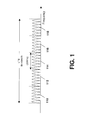
- Figure 1 shows a frequency spectrum in which various bandwidths of 20 MHz have been allocated as carriers. In particular, five carriers are shown in the example of Figure 1 , each having a width of 20 MHz. These are illustrated by reference numerals 110 , 112 , 114 , 116 and 118 .
- the system and method of the present disclosure is not limited to having five uplink component carriers, and more or fewer component carriers can be used in a particular system. Further, the present disclosure is not meant to be limited to a bandwidth of 20 MHz and a greater or lesser bandwidth allocation is possible.
- carrier aggregation may occur with carriers located in the same frequency band or certain carriers may be located in non-adjacent or non-contiguous frequency bands. For example, one carrier may be located in the 2 GHz frequency band and a second non-adjacent aggregated carrier may be located at the 800 MHz frequency band.
- carrier component carrier
- CC Component Carrier
- each radio barrier 210 maps onto a separate logical channel 220.
- Signaling Radio Bearers (SRBs) 212 carry control-plane signaling messages.
- SRBO corresponds with the Common Control Channel (CCCH) 222 which is used only when an UE does not have a regular connection with a Dedicated Control Channel (DCCH) 224.
- the other two SRBs 212 map to separate DCCHs 224 after a connection has been established.
- SRB1 is used to carry control-plane messages originating from the Radio Resource Control (RRC) layer
- SRB2 is used to carry control-plane messages originating from the Non-Access Stratum (NAS).
- RRC Radio Resource Control
- NAS Non-Access Stratum
- Radio Bearers 214 carry user-plane traffic.
- a separate Dedicated Traffic Channel (DTCH) 226 is set up for each active DRB.
- Radio Bearers can be considered to conceptually represent the interface between the RRC (Signaling Radio Bearers) or user-plane Internet Protocol (IP) and Layer 2.
- logical channels 220 can be considered to represent specific Packet Data Convergence Protocol (PDCP) and Radio Link Control (RLC) entity pairings.
- Transport channels 230 can be considered conceptually to represent the interface between the Medium Access Control (MAC) and the physical layer.
- Physical channels 240 represent how data is actually carried over the air at the physical layer.
- All of the uplink logical channels 220 map to the Uplink Shared Channel (UL-SCH) 232 at the transport channel 230 level, which in turn maps to the Physical Uplink Shared Channel (PUSCH) 242 for over-the-air transmission.
- UL-SCH Uplink Shared Channel
- PUSCH Physical Uplink Shared Channel
- the Random Access Channel (RACH) 234 transport channel maps to the Physical Random Access Channel (PRACH) 244 physical channel for performing random accesses
- the Physical Uplink Control Channel (PUCCH) 246 physical channel carries physical layer signaling to the evolved Node B (eNB).
- eNB evolved Node B
- uplink carrier aggregation there may be a separate PUSCH 242 for each individual uplink carrier, although only one PUSCH is shown with regard to the example of Figure 2 .
- FIG 3 shows the general structure and basic functionality of the three E-UTRA Layer 2 sublayers for the uplink.
- TM RLC Transparent Mode RLC
- RLC layer 340 provides a segmentation and Automatic Repeat Request (ARQ) module 342.
- ARQ Automatic Repeat Request
- the logical channel traffic is then provided to MAC layer 310.
- Uplink MAC 310 is responsible for scheduling and priority handling of the multiple logical channels, and then multiplexing the scheduled traffic from the uplink logical channels into UL-SCH MAC Protocol Data Units (PDUs) that are then transmitted over the air by the physical layer.
- PDUs Protocol Data Units
- a scheduling/priority handling module 312 creates scheduling and priority handling for each logical channel.
- the logical channel traffic is then multiplexed in multiplexing module 314 and the Hybrid Automatic Repeat Request (HARQ) module 316 has a separate HARQ entity, shown as 318 and 320 in the example of Figure 3 , for each of the configured uplink Component Carriers (CCs).
- HARQ Hybrid Automatic Repeat Request
- CCs configured uplink Component Carriers
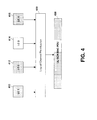
- scheduling/priority handling module 312 and multiplexing module 314 is illustrated below with regard to Figure 4 , which shows an example Uplink Shared Channel (UL-SCH) MAC PDU resulting from the logical channel scheduling and multiplexing functionality.
- UL-SCH Uplink Shared Channel
- four logical channels for 410, 412, 414 and 416, are provided to the logical channel prioritization module 420, which then provides its output as multiplexed data 430.
- the logical channels are multiplexed together.
- the E-UTRA logical channel prioritization procedure is responsible for allocating uplink traffic from the active logical channels to any uplink resource assignments that are received.
- the procedure is outlined in Section 5.4.3.1 of the 3 rd Generation Partnership Project technical specification 36.321, TS 36.321 "3 rd Generation Partnership Project; Technical Specification Group Radio Access Network; Evolved Universal Terrestrial Radio Access (E-UTRA); Medium Access Control (MAC) protocol specification (Release 8)". Version 8.7.0, 2009-09, the contents of which are incorporated herein by reference.
- the procedure is generally a leaky token bucket scheduler.
- Figure 5 illustrates a generic leaky token bucket scheduler example. This is not meant to be limiting to LTE algorithms or the present disclosure, but is meant to provide illustration of such a system.
- a first bucket 510 and a second bucket 512 exist, and represent logical channels A and B, respectively.
- the buckets, as illustrated in Figure 5 are different sizes and in particular, bucket 510 can accommodate five tokens whereas 512 can accommodate three tokens.
- Each bucket has tokens added to it at a particular rate. In the example of Figure 5 , every 10 milliseconds, 4 tokens are added to bucket 510 and 2 tokens are added to bucket 512.
- bucket 510 has four tokens and bucket 512 has two tokens.
- an uplink grant is provided which allows the resources associated with the tokens to be sent in the uplink direction.
- Each data packet or information that is to be sent requires a token to send it.
- the resource assignment that is received can handle 4 packets. Assuming that equal priorities are given to bucket 510 and 512 , each bucket provides 2 tokens so that 2 packets are sent for each of the buckets.
- the second bucket 512 has only 1 token remaining and therefore only 1 packet associated with bucket 512 (i.e. packet B3) is sent at the 14 millisecond time marker.
- the remaining 3 tokens from bucket 510 are also utilized to fill the transmission with packets A3, A4 and A5.
- a Prioritized Bit Rate (PBR) for each logical channel is provided by RRC. This determines the minimum bit rate at which the logical channel should be able to send data over a specified period of time.
- Available PBR settings for logical channels include 0, 8, 16, 32, 64, 128, 256 and infinity kilobytes per second, where 1 kilobyte is defined as equal to 1000 bytes.
- a Bucket Size Duration (BSD) value for each logical channel is also provided by RRC.
- Available bucket size durations include 50, 100, 150, 300, 500 and 1000 milliseconds, which is referred to as the BucketSizeDuration field of the LogicalChannelConfig information element in Section 6.3.2 of TS 36.331.
- the bucket size for a given logical channel may be obtained by multiplying the channel's PBR by the channel's BSD.
- the bucket for each logical channel also includes a priority.
- MAC control elements if available, are first to be scheduled to any uplink transmission allocation.
- Table 1 the relative priorities of different MAC control elements and logical channel traffic that are considered when the Uplink Scheduler is filling the MAC PDU are described.
- MAC control elements have higher priority than logical channel traffic with the exception of a padding BSR which has the lowest priority.
- uplink CCCH traffic from SRB0 also has a higher priority than MAC control elements.
- Each logical channel is assigned a priority (with increasing priority values indicating a lower priority level), a prioritized bit rate, and a bucket size duration.
- B J represents the current bucket contents for logical channel j. This quantity is initialized at zero when the logical channel is first established and is incremented by the PBR J (which may be normalized to units of bytes per subframe) for each subframe.
- the bucket contents B J at any particular time are typically hard-limited to never exceed a Maximum Bucket Size (MBS j ).
- the UE allocates resources within the current uplink MAC PDU to active logical channels by the following:
- steps 1 and 2 together may be referred to collectively as the PBR allocation procedural step, and step 3 may be referred to as the remaining resource allocation procedural step.
- the procedural steps of 1 and 2 are used to allocate the resources associated with tokens to the uplink channel PDU.
- the PDU may have leftover room remaining after all of the token allocation. That left-over room is then provisioned based on the remaining resource allocation procedure.
- a logical channel has various parameters defined in Section 6.3.2 of TS 36.331. These are shown below with regard to Table 2: TABLE 2 - Logical Channel Configuration Parameters Parameter Description Possible Values Priority Assigns a priority level to the logical channel. Smaller numeric values correspond to higher priority levels (i.e. 1 is the highest priority).
- 1-16 Prioritized Bit Rate (PBR) Provides a "guaranteed" bit rate that should be achieved for the corresponding logical channel (provided that the eNB assigns sufficient uplink resources). 0, 8, 16, 32, 64, 128, 256, Infinity (kB/s, kilobytes (1000 bytes) per second) Bucket Size Duration Used for resource allocation during logical channel prioritization by the UE on the uplink.
- Logical Channel Group Optionally assigns this channel to a Logical Channel Group, which may also include other logical channels.
- LCGs are used when the UE generates BSRs (Buffer Status Reports). 0-3
- the channel priorities, Prioritized Bit Rate and Bucket Size Durations are used during logical channel prioritization procedures as described above.
- the logical channel group configuration is used for reporting buffer status information through buffer status reports.
- control-plane messages are given the highest priority in terms of priority level (priority is 1 for uplink CCCH and SRB1, and priority is 3 for SRB2) and the PBR is set to infinity. All three of these control-plane logical channels are grouped together into Logical Channel Group 0. Each user-plane logical channel (i.e. DRBs) would likely be placed into one of the other three Logical Channel Groups (LCGs), although this is up to the eNB implementation.
- priority level priority is 1 for uplink CCCH and SRB1, and priority is 3 for SRB2
- PBR is set to infinity. All three of these control-plane logical channels are grouped together into Logical Channel Group 0. Each user-plane logical channel (i.e. DRBs) would likely be placed into one of the other three Logical Channel Groups (LCGs), although this is up to the eNB implementation.
- LCGs Logical Channel Groups
- the logical channel prioritization algorithm described above is designed to work with a single uplink carrier.
- the solution may not work very well.
- Various factors including the fact that uplink carriers may have different coverage characteristics and performance and that multiple uplink grants may be received for the same subframe and can therefore be processed at the same time may cause the above single carrier algorithm to produce sub-optimal results.
- Figure 6 is an example in which two uplink carriers are shown, each having different cell coverage characteristics.
- a first carrier 610 has a broader coverage then a second carrier 612.
- lower frequency carriers have lower building penetration losses and are less affected by other environmental attenuators such as tree foliage. Consequently, for a given transmission power setting at a UE, a lower frequency carrier may have wider cell coverage than a higher frequency carrier.
- Different uplink carriers may also be subject to varying levels of uplink interference from other UEs that are transmitting at the same time and on the same resources, including but not limited to, neighboring cells. Depending upon possible uplink interference coordination between eNBs, the amount of uplink interference on different carriers may vary.
- Different transmission modes such as transmission diversity (TxD) and spatial multiplexing (SM) could be used on the uplink for UEs with multiple transmit antennas.
- TxD transmission diversity
- SM spatial multiplexing
- UE transmitter power UE transmitter power
- UE PA Power Amplifier
- a particular cell deployment may include a virtual uplink carrier where a cell may have its own uplink carriers, but may also be able to advertise and allocate virtual uplink carriers from neighboring cells.
- a virtual uplink carrier where a cell may have its own uplink carriers, but may also be able to advertise and allocate virtual uplink carriers from neighboring cells.
- This is illustrated in Figure 7 where the UE 710 transmits to a serving eNB 720 on uplink carrier f 2 and to eNB 730 on uplink carrier f 3 , which the UE 710 believes is an uplink carrier associated with eNB 720 . Since transmissions on different uplink carriers are actually directed to completely different eNBs in this deployment scenario, it would generally be expected that the transmission channel conditions for a virtual carrier as compared to a non-virtual carrier could be quite different, even if the two carriers are adjacent or nearly adjacent in frequency.
- uplink carriers may have different traffic loadings, depending on what other UEs are active within the same cell. Some UEs may only be single-carrier capable, or may only be able to operate on a subset of all of the uplink carriers that are available from a particular eNB. For an uplink carrier that is heavily loaded, it may be more difficult for the eNB to schedule quick uplink HARQ retransmissions when such retransmissions are required. That is, on a lightly loaded carrier, uplink HARQ retransmissions may be able to be scheduled with only the minimum 8 ms delay following the previous uplink HARQ transmission of the same data.
- uplink HARQ retransmissions may be subject to a greater delay due to the uplink resources having to be shared among a larger number of UEs.
- an eNB may be able to provide the same uplink resources for a synchronous non-adaptive UL HARQ retransmission 8 ms later, or a heavily loaded eNB may need to grant those resources to another higher-priority UE, thereby temporarily delaying UL HARQ retransmission opportunities for the first UE.
- the main uplink scheduler which allocates the resources to the UEs.
- This uplink scheduler is located at the eNB, while the actual uplink data is located at the UE. In other words, there is no co-location of the primary scheduler and the pending uplink data.
- the uplink scheduler at the eNB has to rely on buffer status report signaling from the UE to know what uplink data is currently queued. Buffer status reports only provide a range rather than an exact value for the amount of uplink data pending. Further, these reports only report pending data on a per logical channel group basis.
- Multiple logical channels may be contained within the same logical channel group, in which case the eNB has no way of determining the exact amount of pending data for a particular logical channel. Further, due to signaling delays, the UE's buffer status may change as new data arrives between the time the buffer status report is signaled by the UE, an uplink grant is issued by the eNB and an uplink transmission is actually made by the UE.
- the eNB uplink scheduler only has limited control via the logical channel priority, prioritized bit rate and bucket size duration configurations, over which logical channel data is actually transmitted by the UE since the predefined logical channel prioritization algorithm is used at the UE. Any enhancement that can provide a greater degree of control to the central uplink scheduler may improve uplink performance.
- the present disclosure provides for logical channel priorities, which are used for uplink logical channel prioritization as described above, to be configured differently for each uplink carrier in a carrier aggregation scenario. This facilitates traffic from different logical channels being directed towards potentially different uplink carriers depending on the exact requirements of the traffic and the performance capabilities of the carriers. In addition, certain logical channels can be configured to be prevented from being transmitted on certain uplink carriers in one embodiment.
- different sets of logical channel priorities could be assigned on a per carrier basis.
- the logical channel priorities could be assigned on a per carrier group basis, where a carrier group is a subset of the total configured carriers. The assigning of the logical channel priorities may be done when multiple uplink carriers are aggregated.
- the assignment of multiple uplink carriers would instruct the UE to favor certain carriers for specific logical channels and would thus facilitate the matching of uplink carrier characteristics and uplink HARQ reliability to traffic originating from different user services on the UE.
- the traffic from a particular logical channel may still be able to be transmitted on any active uplink carrier however, even if that logical channel is configured to have a low priority for a particular uplink carrier, especially if no traffic is pending for the other logical channels.
- Figure 8 shows a process diagram for a user equipment. The process starts at block 810 and proceeds to block 812 in which the UE receives a set of logical channel priorities on a per carrier basis. The process then proceeds to block 814 in which the set of logical channel priorities are applied to the logical channels for each of multiple aggregated carriers.
- an additional priority setting of "forbidden” could be added for a per carrier priority setting for a logical channel.
- a per carrier priority setting for a logical channel could be added for a per carrier priority setting for a logical channel.
- the "forbidden” designation could utilize an existing priority setting such as the use of priority setting "16" to designate the forbidden value in one embodiment. Alternatively, other priority settings could be added.
- an UE operating with two active uplink carriers and two logical channels exists.
- Each logical channel has the same relative priority and PBR.
- uplink grants are received for each of the two active carriers.
- the use of a Release 8 logical channel prioritization algorithm when processing the simultaneous uplink grants sequentially may result in the UE filling half of each MAC PDU with data for each of the two logical channels.
- Figure 9 the first logical channel traffic 910 fills half of the subframe for uplink carrier 920 .
- the second logical channel traffic 912 fills the other half of the subframe for uplink carrier 920 .
- first logical channel traffic 910 fills half of the subframe for uplink carrier 930 and similarly, logical channel traffic 912 fills the other half of the subframe for uplink carrier 930 .
- splitting of the data between two carriers creates extra overhead in the header information that needs to be provided in each of the segments on each carrier.
- two additional headers would be required if the approach of Figure 9 is utilized.
- logical channel traffic 910 utilizes the entire subframe of uplink carrier 920 .
- Further logical channel traffic 912 utilizes the entire subframe of uplink carrier 930 .
- logical channel 910 may be configured such that carrier 920 has priority 1 and carrier 930 has priority 2.
- logical channel 912 may be configured such that carrier 930 has priority 1 and carrier 920 has priority 2.
- the MAC PDU contents would be as shown in Figure 10 .
- carrier 920 is only carrying traffic from the first logical channel and carrier 930 is only carrying traffic from the second logical channel.
- a similar benefit can be obtained when the eNB can use the different logical channel priority sets to control UE logical channel prioritization over a time period greater than one subframe.
- SPS semi-persistent scheduling
- Two logical channels therefore exist, and it can be reasonably assumed that the real-time voice service logical channel's priority is configured to be higher then the non-real-time file transfer logical channel's priority.
- two uplink carriers have been assigned to the UE.
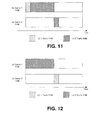
- the voice service assigned logical channel priorities are such that it can transmit on either carrier, then the situation of Figure 11 may result.
- the UE has been issued a large uplink grant for a particular subframe.
- the logical channel priorities are such that the small voice packet which is the highest priority is inserted at the beginning of the MAC PDU of the first subframe, shown as traffic 1112 in carrier 1120 .
- the remainder of the subframe on carrier 1120 includes the large amount of file data, shown as traffic 1130 .
- the first logical channel which carries the voice traffic 1112 is forbidden from transmitting on carrier 1120 , then the same set of uplink grants will result in the situation illustrated by Figure 12 .
- the logical channel priority settings result in a first large uplink grant on carrier 1120 being filled only with the file traffic 1130 from the second logical channel.
- the voice traffic 1112 from the first logical channel is "intentionally" delayed by the logical channel priority settings so that the voice packet will be inserted into the smaller uplink grant on carrier 1140 in the following subframe. This results in less traffic fragmentation, resulting in lower overhead, and facilitates any necessary uplink HARQ transmissions of real-time voice traffic (which is intentionally encapsulated into a small MAC PDU).
- the examples of Figures 11 and 12 could be reduced to a single uplink carrier case of E-UTRA Release 8.
- the UE has an SPS service such as voice that is currently active as well as performing other data transfer on different logical channels, then when an SPS grant is configured, the UE knows in advance when it will be able to transmit SPS data.
- the proposed solution is to associate logical channel priorities with a certain resource dimension where the resource dimension can be component carriers, subframes or a combination of both.
- the above approach may be used to maintain existing flexibility of uplink logical channel prioritization and provide potential additional flexibility if so desired. That is, the use of the Release 8 logical channel prioritization approach by the UE is still available to the eNB when the eNB signals to the UE to use a single logical channel configuration (i.e. logical channel priorities) that applies equally to all uplink carriers or else uses the same logical channel configuration and logical channel priorities for each configured uplink carrier. Hence, no functionality is taken away from E-UTRA Release 8, but additional flexibility is made available if desired. That is, backward compatibility with E-UTRA Release 8 is maintained.
- the Logical Channel Prioritization procedure is applied when a new transmission is performed.
- RRC controls the scheduling of uplink data by signalling for each logical channel: priority where an increasing priority value indicates a lower priority level, prioritisedBitRate which sets the Prioritized Bit Rate (PBR), bucketSizeDuration which sets the Bucket Size Duration (BSD).
- priority where an increasing priority value indicates a lower priority level
- prioritisedBitRate which sets the Prioritized Bit Rate (PBR)
- bucketSizeDuration which sets the Bucket Size Duration (BSD).
- logical channel prioritization shall use the logical channel priorities configured for the carrier to which the uplink grant corresponds.
- the priority for a logical channel on a particular uplink carrier may be configured to "Forbidden", in which case the corresponding logical channel shall not be considered for transmission on that carrier.
- the UE shall maintain a variable Bj for each logical channel j.
- Bj shall be initialized to zero when the related logical channel is established, and incremented by the product PBR x TTI duration for each TTI, where PBR is Prioritized Bit Rate of logical channel j.
- PBR Prioritized Bit Rate of logical channel j.
- the value of Bj can never exceed the bucket size and if the value of Bj is larger than the bucket size of logical channel j, it shall be set to the bucket size.
- the bucket size of a logical channel is equal to PBR x BSD, where PBR and BSD are configured by upper layers.
- the UE shall perform the following Logical Channel Prioritization procedure when a new transmission is performed:
- the UE shall not transmit data for a logical channel corresponding to a radio bearer that is suspended (the conditions for when a radio bearer is considered suspended are defined in [8]).
- the UE shall take into account the following relative priority in decreasing order:
- the configuration of the priorities may be performed based on the following.
- a first option for configuration is semi-static configuration via RRC signaling.
- the approach would assign specific priorities for each configured uplink carrier whenever a new logical channel is configured. This may require modification of the LogicalChannelConfig information element in Section 6.3.2 of TS 36.331. Additionally, if a new uplink carrier is added to the existing configuration, logical channel priority values may be provided that correspond to that new uplink carrier for all currently configured logical channels.
- the LogicalChannelConfig information element or other equivalent information element can be included in the same RRC signaling message that configures the uplink component carrier assignment for the UE.
- Table 3 shows the modified LogicalChannelConfig field descriptions (where modifications have been shown in boldface text).
- the priority in the LogicalChannelConfig field description has been amended to include that logical channel priorities are provided for a maximum number of uplink carriers, even if not all of these carriers are configured at the UE. Further, a priority value of 16 is assumed to correspond to the "Forbidden" state.
- TABLE 3 LogicalChannelConfig field descriptions priority Logical channel priority in TS 36.321 [6]. Value is an integer. Logical channel priorities are ; i provided for the maximum number of uplink carriers, even if not all of these carriers are configured at the UE.
- Value kBps0 corresponds to 0 kB/second
- kBps8 corresponds to 8 kB/second
- kBps16 corresponds to 16 kB/second and so on.
- Infinity is the only applicable value for SRB1 and SRB2 bucketSizeDuration Bucket Size Duration for logical channel prioritization in TS 36.321 [6].
- Value ms50 corresponds to 50 ms
- ms100 corresponds to 100 ms and so on.
- the logical channel configuration information element may look like (where modifications have been shown in boldface text):
- a new LogicalChannelConfig may be sent via RRC signaling. This has the advantage that it is robust in terms of transmission reliability and RRC acknowledgment provided back to the eNB.
- a semi-dynamic adaptation through MAC control elements is possible.
- This approach allows logical channel priorities for different uplink carriers to be modified more easily and more quickly by making use of MAC control elements.
- multiple sets of logical channel priorities can be configured semi-statically via RRC signaling.
- up to four logical channel priority sets could be configured. However, this is not meant to be limiting and in other embodiments other numbers of logical channel priority sets could be configured.
- a MAC control element could then be used in a semi-dynamic fashion (where semi-dynamic is slower then dynamic but faster then semi-static) to associate a particular channel priority with one or more of the currently configured active uplink carriers. This would allow relatively fast reconfiguration of logical channel priorities for each uplink carrier at a given UE, but would not incur much signaling overhead since MAC control elements would be small and would only need to be sent when a remapping of logical channel priority sets to an uplink carrier is desired.
- FIG. 13 shows an octet of the MAC control element that can assign one of four logical channel priority sets for each of four uplink carriers.
- RRC signaling has configured four different sets of logical channel priorities, as an example, numbered 0 through 3 for the uplink carriers currently configured at the UE, a maximum of five uplink carriers can be activated at a UE, so in one embodiment a maximum of four different sets of logical channel priorities would provide sufficient flexibility for logical channel configuration purposes.
- a MAC control element would only need to be 1 byte in length in order to configure the remaining four uplink carriers, with an example of such a MAC control element being illustrated in Figure 13 .
- the logical channel priority sets can be signaled for up to four non-reference uplink carriers.
- Each logical channel priority set value is a 2-bit value that selects for a particular carrier from among four configured channel priority sets. If an eNB wishes to change the logical channel priority sets for only a subset of the currently configured uplink carriers, the eNB would simply reuse the existing LCPS values for the uplink carriers whose logical channel priority sets the eNB does not wish to change. In other words, if the eNB would like to change the value of the logical channel priority set for carrier 2, then the logical channel priority set values for carrier 1, carrier 3 and carrier 4 would remain the same as previously sent.
- Each 2-bit LCPS k value from Figure 13 above would then select an LCPS from Table 4 to use on carrier k.
- LCPS 2 may have a binary value of 01 indicating that carrier 2 should use LCPS 1 from Table 4 below.
- Binary field values of 00, 01, 10 and 11 would be used to indicate LCPS 0, 1, 2 and 3, respectively.
- TABLE 4 Logical Channel Logical Channel Priorities LCPS 0 LCPS 1 LCPS 2 LCPS 3 1 0 0 0 Not configured /Not used 2 2 2 2 3 4 Forbidden 15 4 4 15 15 5 5 5 5 Forbidden 6 5 5 Forbidden
- LogicalChannelConfig field descriptions are shown below with regard to Table 5 for the use of logical channel priority sets (where modifications have been shown in boldface text). In particular, the priority field has been amended to indicate that logical channel priority values are provided for a maximum number of logical channel priority sets. A priority value of 16 is also assumed to correspond to "Forbidden”. TABLE 5 LogicalChannelConfig field descriptions priority Logical channel priority in TS 36.321 [6]. Value is an integer. Logical channel priorities are provided for the maximum number of logical channel priority sets. A priority value of 16 is assumed to correspond to 'Forbidden' (i.e. traffic from the logical channel shall not be sent on the corresponding uplink carrier).
- Value kBps0 corresponds to 0 kB/second
- kBps8 corresponds to 8 kB/second
- kBps16 corresponds to 16 kB/second and so on.
- Infinity is the only applicable value for SRB1 and SRB2 bucketSizeDuration Bucket Size Duration for logical channel prioritization in TS 36.321 [6].
- Value ms50 corresponds to 50 ms
- ms100 corresponds to 100 ms and so on.
- Conditional presence Explanation UL The field is mandatory present for UL logical channels; otherwise it is not present.
- DCI downlink control information
- the downlink control information on the Physical Downlink Control Channel (PDCCH) that provides the uplink grant could be modified so that logical channel priorities for a particular grant could be changed dynamically. For example, if the approach of defining up to four logical channel priority sets through RRC signaling described above is used, a 2-bit field could be added to each DCI 0 (or uplink grant DCI) to indicate which set of logical channel priorities is to be used when generating a MAC PDU for the corresponding uplink grant. This approach would provide maximum flexibility and dynamically control the uplink logical channel prioritization scheme at the UE.
- the DCI change could be made to Section 5.3.3.1.1 of technical specification 36.212 of the 3GPP technical specifications. The specification change could look like (where modifications have been shown in boldface text):
- DCI format 0 is used for the scheduling of PUSCH.
- LCPS selection field as defined in Section 6.3.2 of 36.331 is added to DCI format 0. This is not meant to be limiting and a shorter or longer LCPS field could be used depending upon the maximum number of LCPS sets that may be configured.
- a particular logical channel it is possible for a particular logical channel to be configured with a priority of "Forbidden" on one or more aggregated uplink carriers.
- a check should be made to ensure that each configured logical channel is able to transmit on at least one uplink carrier.
- the logical channel should not be configured as "Forbidden” on all currently active uplink carriers so that a transmission blocking of a particular logical channel does not occur.
- the preference could be listed as a note within the appropriate technical specification (specification 36.321 or 36.331, depending upon the exact embodiment used for assigning logical channel priorities for multiple uplink carriers). Such a change may be as follows:
- the UE may also, in one embodiment perform error checking when a carrier logical channel reconfiguration occurs or when a carrier deactivation occurs to ensure that each configured logical channel is still permitted to transmit on at least one currently active uplink carrier.
- uplink grants when sufficient data is queued or available is generally desirable since the grants are otherwise wasted.
- One case where this may be seen is where there are one or more logical channels that are forbidden from transmitting on a particular uplink carrier. If uplink grants on other carriers are filled first, then conceivably a case could exist where space on an uplink grant is still available but the only remaining pending data is from logical channels that are forbidden from transmitting on the remaining carrier.
- the prioritized bit rate for each logical channel should be met assuming sufficient uplink resources are granted by the eNB.
- a semi-static configuration of relative priorities of uplink carriers is possible.
- all uplink carriers are semi-statically assigned a relative priority through RRC signaling. These priorities determine the order in which uplink grants are processed when multiple uplink grants are received for the same subframe.
- the UE sorts the grants into order from the highest priority carrier to the lowest. Each grant is then processed sequentially following the existing logical channel prioritization scheme with the addition that the logical channel priorities for the current carrier are used. Thus, other than sorting of uplink grants, no consideration of having multiple uplink grants in the same subframe is made.
- a tie-breaking rule can be applied when sorting those grants into order. Possibilities for such a tie-breaking rule would include options such as the following:
- the process then ends at block 1420 .
- Section 5.4.3.1 of TS 36.321 may be changed to accommodate the above. This is seen as follows (where modifications have been shown in boldface text):
- the Logical Channel Prioritization procedure is applied when a new transmission is performed.
- RRC controls the scheduling of uplink data by signalling for each logical channel: priority where an increasing priority value indicates a lower priority level, prioritisedBitRate which sets the Prioritized Bit Rate (PBR), bucketSizeDuration which sets the Bucket Size Duration (BSD).
- priority where an increasing priority value indicates a lower priority level
- prioritisedBitRate which sets the Prioritized Bit Rate (PBR)
- bucketSizeDuration which sets the Bucket Size Duration (BSD).
- the UE shall maintain a variable Bj for each logical channel j.
- Bj shall be initialized to zero when the related logical channel is established, and incremented by the product PBR x TTI duration for each TTI, where PBR is Prioritized Bit Rate of logical channel j.
- PBR Prioritized Bit Rate of logical channel j.
- the value of Bj can never exceed the bucket size and if the value of Bj is larger than the bucket size of logical channel j, it shall be set to the bucket size.
- the bucket size of a logical channel is equal to PBR x BSD, where PBR and BSD are configured by upper layers.
- the UE shall perform the following Logical Channel Prioritization procedure when a new transmission is performed:
- the UE shall not transmit data for a logical channel corresponding to a radio bearer that is suspended (the conditions for when a radio bearer is considered suspended are defined in [8]).
- the UE shall take into account the following relative priority in decreasing order:
- Figure 15 shows the priority of logical channels assigned to a particular carrier.
- logical channel 1 is assigned a priority of 1 for all three carriers.
- Logical channel 2 is assigned a priority of 3 for carrier 1, a priority of 3 for carrier 2 and a priority of 8 for carrier 3.
- Logical channel 3 is assigned a priority of 15 for carrier 1, priority of 2 for carrier 2, and is forbidden from transmitting on carrier 3.
- all carrier/logical channel combinations are sorted into order from the highest priority to the lowest priority.
- the result of this sorting is shown with regard to Figure 16 . Since logical channel 3 is forbidden from transmitting on carrier 3, in the embodiment of Figure 16 this carrier/logical channel pairing is excluded from the sorted priority list of Figure 16 .
- sorting position 1 has carrier 1 with logical channel 1 having priority 1.
- sorting position 2 has carrier 2 with logical channel 1 and a priority of 1 and so on.
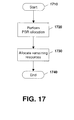
- the prioritization process is generally a two-step process where the first step involves allocating PBR resources for each logical channel and the second step involves allocating logical channel traffic to the remaining resources on a strict logical channel priority basis.
- PBR resources can generally be represented by tokens in a bucket.
- each logical channel has particular bucket contents that are allocated through the PBR allocation process of block 1720 .
- the process proceeds to block 1730 in which the remaining resources (if any) are allocated. Thus, if there are remaining uplink grants that have not been fully utilized through the PBR allocation process, these are filled through the remaining resources block 1730 .
- the UE processes each of the sorted carrier and logical channel combinations in turn and assigns data from the corresponding logical channel j if B j for that logical channel is positive and there is still data available for logical channel j.
- B j (and T j ) is decremented by the amount of data granted to logical channel j.
- Figure 18 shows a result of the PBR allocation.
- Figure 18 includes a running remaining grant size 1810 which shows the remaining grant size for each carrier, a running Bucket Contents field 1820 which is utilized for the bucket allocation of the PBR allocation process and a pending traffic field 1830 which shows the remaining amount of pending traffic for each logical carrier.
- carrier 1 has a grant size of 100 bytes
- carrier 2 has a grant size of 200 bytes
- carrier 3 has a grant size of 300 bytes.
- logical channel 1 has a bucket content size of 100 bytes
- logical channel 2 has a bucket content size of 150 bytes
- logical channel 3 has a bucket content size of 75 bytes.
- logical channel 1 has a total pending traffic size of 50 bytes
- logical channel 2 has a total pending traffic size of 800 bytes
- logical channel 3 has a total pending traffic size of 800 bytes.
- the PBR allocation then utilizes the sorting positions as represented in Figure 16 above and utilizes the first row, which has carrier 1 using logical channel 1.
- 50 bytes from logical channel 1 are applied to carrier 1.
- the grant of carrier 1 is thus reduced by 50 bytes and the bucket contents for logical channel 1 are reduced by 50 bytes and the pending traffic for logical channel 1 is reduced by 50 bytes to become 0 bytes.
- the bucket contents were 100 bytes and the remaining grant size was 100 bytes, only 50 bytes of traffic existed on logical channel 1 and therefore only 50 bytes were allocated.
- sorting position 2 of Figure 16 carrier 2 is allocated for logical channel 1. However, since logical channel 1 has no further traffic pending, the allocation at sorting position 2 is ignored in the example of Figure 18 . Similarly, sorting position 3 from Figure 16 shows an allocation of logical channel 1 to carrier 3. However, as logical channel 1 has no more data to send, this is also ignored in the step 3 of Figure 18 .
- Sorting position 4 of Figure 16 shows that carrier 2 is assigned logical channel 3. Based on this, logical channel 3 is examined and is shown to have 75 bytes as its bucket contents. Thus, a maximum of 75 bytes can be sent. Since the remaining grant size of carrier 2 is greater than 75 bytes and since the pending traffic for logical channel 3 is also greater than 75 bytes, 75 bytes is allocated to logical channel 3 on carrier 2. This reduces the grant size for carrier 2 from 200 bytes to 125 bytes, reduces the bucket contents for logical channel 3 to zero bytes and reduces the pending traffic for logical channel 3 from 800 bytes to 725 bytes.
- the process then proceeds to sorting position 6, which allocates logical channel 2 to carrier 2.
- Carrier 2 has 125 bytes remaining in its grant, while logical channel 2 has 100 bytes remaining in its bucket contents and 750 bytes remaining in pending traffic.
- 100 bytes are allocated from logical channel 2 to carrier 2, leaving a grant size of 25 bytes for carrier 2, bucket contents of 0 bytes for logical channel 2 and pending traffic of 650 bytes for logical channel 2.
- logical channel 2 is allocated to carrier 3. However, logical channel 2 has 0 bytes remaining in its bucket contents and thus, this sorting position is ignored. The process then proceeds to sorting position 8 from Figure 16 and determines that logical channel 3 is allocated to carrier 1. However, carrier 1 has no further grant room left and therefore this is also ignored.
- the remaining resources are then allocated to logical channels based on the logical channel priorities.
- the same sorting order as that found in Figure 16 above is used.
- the use of the sorting of Figure 16 is however not meant to be limiting and other sorting orders could be used for the remaining resources processing.
- FIG 19 the fields 1810 , 1820 and 1830 from Figure 18 are also represented.
- the initial values are those which are remaining after the PBR allocation step.
- carrier 1 has a grant of 0 bytes remaining
- carrier 2 has a grant of 25 bytes remaining
- carrier 3 has a grant of 300 bytes remaining.
- logical channel 1 has bucket contents of 50 bytes remaining
- logical channel 2 has bucket contents of 0 bytes remaining
- logical channel 3 has bucket contents of 0 bytes remaining.
- the bucket contents are not used and therefore do not matter.
- pending traffic for each logical channel is illustrated in field 1830 , which shows that logical channel 1 has 0 bytes remaining, logical channel 2 has 650 byes remaining and logical channel 3 has 725 bytes remaining.
- logical channel 1 is allocated to carrier 1. However, logical channel 1 has no pending traffic remaining and carrier 1 has no grant size remaining, therefore this is ignored.
- logical channel 1 is assigned to carrier 2. Again, logical channel 1 has no pending traffic and therefore this is ignored.
- logical channel 1 is allocated to carrier 3. Again, logical channel 1 has no pending traffic and therefore this is ignored.
- Logical channel 3 is allocated to carrier 2.
- Logical channel 3 has 725 bytes remaining and carrier 2 has 25 bytes remaining in its grant. Therefore, 25 bytes are allocated from logical channel 3 to carrier 2 leaving 0 bytes in the remaining grant size for carrier 2 and 700 bytes of pending traffic for logical channel 3.
- logical channel 2 is allocated to carrier 3.
- Logical channel 2 has 650 bytes remaining and carrier 3 has 300 bytes remaining in its grant. Therefore 300 bytes are allocated from logical channel 2 to carrier 3 leaving a grant size of 0 bytes for carrier 3 and 350 bytes of pending traffic for logical channel 2.
- the complete grant is utilized for each of the three carriers.
- the final resource allocation for the uplink grant corresponding to each carrier is shown below with regard to Table 6. This shows that logical channel 1 has 50 bytes on carrier 1, logical channel 2 has 50 bytes on carrier 1, 100 bytes on carrier 2 and 300 bytes on carrier 3 and logical channel 3 has 100 bytes on carrier 2. TABLE 6 - Final allocations Carrier 1 Carrier 2 Carrier 3 Total (per LC) Logical Channel 1 50 bytes 50 bytes Logical Channel 2 50 bytes 100 bytes 300 bytes 450 bytes Logical Channel 3 100 bytes 100 bytes Total (per carrier) 100 bytes 200 bytes 300 bytes
- Figure 16 illustrates instances where different carriers or logical channel combinations have the same priority.
- some sort of "tie-breaking" rule must be utilized when sorting all possible combinations into order by priority.
- the sorting was merely done by carrier and logical channel index.
- Other alternative implementations exist. These could include sorting by the grant size of a carrier where the carrier with the largest or smallest grant size is sorted first.
- Carriers that have forbidden logical channels may be sorted first in some instances, which will ensure that these grants are utilized before grants from other carriers to ensure that the former grants are not left under-utilized after the resources have been allocated to the other carriers.
- Semi-static configuration is possible in configuring a preferred order for carriers and logical channels for breaking ties. Alternatively, random or pseudo-random tie-breaks can occur.
- tie-breaking rules that may apply specifically to PBR allocation procedural step include:
- Tie-breaking rules that may apply specifically to the remaining resource allocation procedural step may include:
- FIG. 20 The above procedure may be shown with a process diagram of Figure 20 .
- the process diagram of Figure 20 starts at block 2010 and proceeds to block 2012 in which a sort is done based on carrier and logical channel priority information as indicated above with regard to Figure 16 and also with regard to the embodiments of the present disclosure.
- Figure 20 only shows an example of one embodiment, and other examples are possible.
- the process then proceeds to block 2020 in which resources are allocated for the particular sorting position based on grant, bucket and pending traffic information.
- the process proceeds to block 2022 in which a check is made to see whether the sorting position currently allocated is the last sorting position. If no, then the process proceeds to block 2024 in which the sorting position is incremented and the process then proceeds back to block 2020 in which the resources are allocated for the new sorting position.
- the allocation of block 2020 was shown above with regard to Figure 18 .
- block 2030 optionally another sort is performed. This is done in cases where the sorting order may be different for the remaining resource allocation.
- each logical channel should transmit on the highest priority carrier for that logical channel.
- some logical channels may have equal priority settings on multiple carriers. In such cases, it may be desirable to select the carrier assignment for those logical channels such that the carrier assignments for other logical channels are optimized for their logical channel priority settings.
- any logical channel that has equal priority settings on multiple carriers will make "a reservation" on those carriers for the appropriate amount of resources such as the bucket contents for the particular logical channel or the remaining resources that are available on those carriers, whichever is less.
- resource assignments are made for other logical channels, a prior reservation for a higher priority logical channel will be removed or canceled if it collides with the resource assignment for the current logical channel.
- the next sorting position is sorting position 4, in which logical channel 3 is allocated to carrier 2 utilizing a priority of 2. Since there are no other priority 2 allocations, this is an assignment rather than a reservation.
- the assignment changes the remaining grant size for carrier 2 from 150 to 75 bytes, reduces the bucket contents for logical channel 3 to 0 bytes and reduces the pending traffic for logical channel 3 to 725 bytes.
- Step 5A the reservation of the 50 bytes on carrier 1 is cancelled, and as shown by Step 5B, carrier 1 is assigned 100 bytes for logical channel 2. This leaves a grant size of 0 bytes remaining on carrier 1, bucket contents of 50 bytes for logical channel 2 and 100 bytes of pending traffic for logical channel 2.
- logical channel 2 is assigned to carrier 2, which has a remaining grant size of 75 bytes.
- Logical channel 2 has 50 bytes of bucket contents remaining. Therefore, 50 bytes are allocated from logical channel 2 to carrier 2, leaving a grant size of 25 bytes on carrier 2.
- Sorting position 7 assigns logical channel 2 to carrier 3. However, logical channel 2 has no bucket contents remaining and therefore, this is ignored.
- Sorting position 8 assigns logical channel 3 to carrier 1. However, carrier 1 has no remaining grant room and therefore this step is also ignored.
- logical channel 1 still has 50 bytes that are reserved on carrier 2 and carrier 3, whereas logical channel 2 has 100 bytes on carrier 1 assigned and 50 bytes on carrier 2 assigned.
- Logical channel 3 has 75 bytes assigned on carrier 2. This is illustrated with regard to Table 7 below. TABLE 7 Logical Channel Carrier 1 Carrier 2 Carrier 3 1 Reserved 50 bytes 50 bytes Assigned 2 Reserved Assigned 100 bytes 50 bytes 3 Reserved Assigned 75 bytes
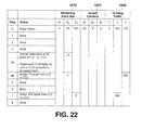
- Figure 22 the sorting order of Figure 16 is used.
- the first three positions of the sorting order assign logical channel 1 to carriers 1, 2 and 3 respectively. Since logical channel 1 has no further pending data these steps are ignored.
- logical channel 3 is assigned to carrier 2. Since carrier 2 has a grant size of 25 bytes remaining plus 50 reserved bytes, the example of Figure 22 cancels the reservation of 50 bytes for logical channel 1 on carrier 2 which causes the reservation of 50 bytes for logical channel 1 on carrier 3 to become an assignment of those bytes.
- the 50 bytes from carrier 2 get added back to the 25 bytes remaining on carrier 2 leaving 75 bytes which are then assigned to logical carrier 3, leaving a remaining grant of 0 bytes for carrier 2 and remaining traffic of 650 bytes for logical channel 3.
- Sorting position 5 allocates logical channel 2 to carrier 1. However, carrier 1 has no remaining grant room and this step is therefore ignored.
- Sorting position 6 allocates logical channel 2 to carrier 2. However, carrier 2 has no remaining grant room and therefore this is also ignored.
- Sorting position 7 allocates logical channel 2 to carrier 3.
- Carrier 3 has 250 bytes of grant remaining and therefore this is assigned to logical channel 2.
- Logical channel 2 therefore has 450 bytes of pending traffic remaining and carrier 3 has 0 bytes remaining in its grant.
- Sorting position 8 then assigns logical channel 3 to carrier 1. However, carrier 1 has no remaining grant room and this step is ignored.
- Table 8 shows the final resource allocations for the uplink grant corresponding to each carrier.
- Table 6 shows the final resource allocations for the uplink grant corresponding to each carrier.
- the traffic from logical channel 1 was assigned to an "optimal" carrier in terms of freeing up space on the other carriers for the other logical channels and logical channel 3 received a greater total allocation while logical channel 2 received a lower total allocation. This results in a set of allocations that may be considered more "fair" from a viewpoint of logical channel 3.
- MAC control elements CE
- MAC control elements are short signaling messages that are included within a MAC PDU that is being transmitted on the uplink to the eNB.
- a Cell Radio Network Temporary Identifier (C-RNTI) MAC control element is used by a UE that already possesses a C-RNTI and which is performing a random access procedure in order to obtain uplink synchronization with the eNB. If a UE does not already posses a C-RNTI, (such as when transitioning from RRC_IDLE to RRC_CONNECTED to establish a connection with an eNB) then the random access procedure is used to obtain uplink synchronization with an eNB and to obtain a C-RNTI from the eNB.
- C-RNTI Cell Radio Network Temporary Identifier
- a UE that is already in an RRC_CONNECTED mode and which already possesses a C-RNTI may lose uplink synchronization with the eNB and thus need to perform a random access procedure in order to regain uplink synchronization.
- the UE includes its existing C-RNTI within a C-RNTI MAC control element so that the eNB can determine which UE is performing a particular random access.
- C-RNTI MAC control elements may also be used following a handover when a UE must obtain uplink synchronization in a new cell.
- a Buffer Status Report (BSR) MAC control element is used to communicate the amount of pending uplink data per logical channel group to the eNB.
- the uplink scheduler at the eNB can then use this information to assign uplink transmission resources to UEs that have data to transmit.
- Each logical channel may be optionally assigned to a logical channel group for the purposes of generating a BSR.
- BSRs may be triggered by events such as a certain time period passing since the previous BSR was transmitted, new uplink data arriving at the UE, among others.
- Padding BSRs may also be added to MAC PDUs that require padding in order to completely fill the available space of the MAC PDU.
- a padding BSR is included to make use of the additional space that is available and which otherwise would be wasted as padding.
- a maximum of only one BSR can be included in any MAC PDU.
- a Power Headroom Report (PHR) MAC control element is used to communicate the available power headroom on an uplink carrier to the eNB. Essentially, this tells the eNB how much extra transmission power is available at the UE in case the eNB wishes to increase the transmission power of the UE through closed loop power control signaling or to assign additional uplink transmission resources to the UE.
- additional uplink transmission resources may include physical resource blocks or modulation and code rate setting.
- Transmission of the C-RNTI MAC control element is part of a random access procedure.
- a UE configured with multiple uplink carriers may need to perform this procedure in order to regain uplink synchronization or upon receiving an order to do so from the eNB via the PDCCH.
- a C-RNTI MAC control element should be transmitted on the same uplink carrier as on which the initial random access preamble was transmitted or on the uplink carrier that the eNB has signaled or on the preconfigured uplink carrier.
- MAC PDU the C-RNTI MAC control element should be included.
- the other MAC control elements are a different case.
- Uplink MAC control element transmission on a multi-carrier situation could be configured to follow various options.
- A. MAC control elements are only transmitted on one uplink carrier
- MAC control elements in one embodiment may be only transmitted on a single uplink carrier.
- the uplink anchor or reference or designated carrier could be utilized in this case.
- the uplink carrier to use is signaled by the eNB. If a particular MAC control element is triggered, that MAC control element is not sent until an uplink grant is received for the particular carrier, even if uplink grants for other carriers are received in the meantime.
- MAC CE preferably carried on a particular carrier but may be sent on other carriers.
- the MAC control element prefers to be carried on a particular uplink carrier but may be sent on a different uplink carrier if that is the only uplink grant available when the MAC control element has been triggered. For example, assuming that a buffer status report has been triggered, if two uplink grants are received in that subframe, one for the reference carrier and one for the non-reference carrier, then the BSR MAC control element will only be included for the MAC PDU for the uplink reference carrier. However, if only uplink grants for non-reference carriers are received in that subframe (and no uplink grant for the reference carrier), the BSR MAC control element will be included in the MAC PDU for a non-reference uplink carrier.
- MAC control elements in this embodiment avoid being carried within a MAC PDU originating from an uplink SPS configuration if non-SPS uplink grants on other carriers are available. This may avoid possible fragmentation of voice packets, for example.
- the chosen uplink carrier to transmit MAC control elements can be different at each transmission opportunity in order to obtain a diversity gain.
- the current system frame number (SFN) and subframe offset within the current 10 ms radio frame a MAC control element counter or a pseudo-random sequence could be used.
- carrier k is the chosen carrier to carry a MAC control element but there is no uplink grant received for that carrier, the UE can send the MAC control element on a non-chosen carrier that has an uplink grant.
- MAC control elements when triggered are included in all uplink carriers that currently have an uplink grant available. This results in greater overhead, since MAC control elements may be duplicated among multiple MAC PDUs. However, this approach may also result in greater signaling robustness and reduced signaling latency since there is a greater probability of at least one of the copies of the MAC control element being successfully received at the eNB on the first transmission attempt.
- the MAC control element when triggered can be sent on any of the uplink carriers that currently have available uplink grants.
- Carrier specific MAC control elements such as a PHR per carrier can be transmitted on the same carrier.
- the PHR of carrier 1 is transmitted on carrier 1 when an uplink grant for carrier 1 is received.
- the eNB scheduling entity for different carriers can be different when one or more uplink virtual carriers are supported.
- some MAC control elements may need to be transmitted to the eNB scheduling a particular uplink carrier to help with the scheduling.
- Carrier common MAC control elements such as BSR can be transmitted to both eNBs and carrier specific MAC control elements (example PHR) can be transmitted to the eNB which "owns" the corresponding carrier.
- the serving eNB can provide information about on which carrier the particular MAC control elements are to be transmitted.
- the UE can transmit the appropriate MAC control elements to that eNB.
- the UE can transmit the appropriate MAC control elements to that eNB.
- BSR MAC control element could be transmitted to eNB 1, eNB 2, or both, while the PHR and C-RNTI MAC control elements for CC1 to CC4 would be transmitted to eNB 1 while the PHR and C-RNTI MAC control elements for CC5 would be transmitted to eNB 2.
- BSR can be defined per carrier, it should be possible to transmit the appropriate BSR MAC control elements to each eNB depending on the particular carrier in question.
- approach B could be used for BSR MAC control elements while approach D could be used for PHR MAC control elements.
- the solutions above also depend on whether or not the Release 8 format for the control element is maintained or whether new enhanced control element formats are adopted for multi-carrier UEs.
- the PHR MAC control element may depend on which release the control element is for. If the Release 8 format is kept, then the PHR MAC control element for a particular uplink carrier can only be transmitted on that carrier, so that the eNB can associate the corresponding power headroom report with the correct uplink carrier. However, if a new Release 10 format is adopted that consolidates power headroom information for multiple uplink carriers into a single message or MAC control element, then the choice of which uplink carrier to use for sending the PHR MAC control element may become more flexible.
- Buffer status reports are generally uplink carrier agnostic since BSRs report the amount of pending data per logical channel group.
- a logical channel group may include one or multiple logical channels. When a new logical channel is configured, it is optionally assigned to a logical channel group.
- BSR MAC control elements transmitted on different uplink carriers could therefore have different values and could be used by the eNB to deduce additional information about the pending uplink data at the pending UE. An example of this is shown below with regard to Table 9, where logical channel groups 1 and 2 contain different logical channels, depending upon which uplink carrier is being considered as a reference. TABLE 9 Logical Channel Group Uplink Carrier 1 Uplink Carrier 2 1 1,2 1,2,3 2 3,4 4
- the eNB could use this extra BSR information to deduce the actual amount of pending data on a per logical channel basis rather then on a per logical group basis.
- the LogicalChannelConfig information element of Section 6.3.2 of TS 36.331 optionally may assign a logical channel to a logical channel group. Consequently, for example, of eight logical channels with two uplink carriers, the logical channel to logical channel group assignments given in Table 11 below could be used. This would allow the UE to report the amount of pending data on a per logical channel basis, with any BSRs transmitted on carrier 1 giving the individual traffic queue sizes for logical channel sizes 1 through 4 and any BSRs transmitted on carrier 2 giving the individual traffic queue sizes for logical channels 5 through 8. TABLE 11 Logical Channel Group Uplink Carrier 1 Uplink Carrier 2 0 1 5 1 2 6 2 3 7 3 4 8
- the above can be implemented on any user equipment on the receiving side and any network element such as an evolved Node B on the sending side.
- the network element On the sending side, the network element will include a communications subsystem to send the information concerning transport layers utilized.
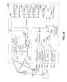
- Figure 23 is a block diagram illustrating a UE capable of being used with various embodiments of the apparatus and method of the present application.
- UE 2300 is typically a two-way wireless communication device having voice, data or both voice and data communication capabilities.
- the wireless device may be referred to as a data messaging device, a two-way pager, a wireless e-mail device, a cellular telephone with data messaging capabilities, a wireless Internet appliance, or a data communication device, as examples.
- UE 2300 is enabled for two-way communication, it will incorporate a communication subsystem 2311, including both a receiver 2312 and a transmitter 2314, as well as associated components such as one or more, embedded or internal, antenna elements 2316 and 2318, local oscillators (LOs) 2313, and a processing module such as a digital signal processor (DSP) 2320.
- LOs local oscillators
- DSP digital signal processor
- An LTE UE may require a subscriber identity module (SIM) card in order to operate on the LTE or LTE-A network.
- SIM subscriber identity module
- the SIM interface 2344 is normally similar to a card-slot into which a SIM card can be inserted and ejected like a diskette or PCMCIA card.
- the SIM card may hold key configuration 2351, and other information 2353 such as identification, and subscriber related information.
- UE 2300 may send and receive communication signals over the network 2319.
- network 2319 can consist of multiple antennas communicating with the UE. These antennas are in turn connected to a network element such as eNB 2370 .
- the network element for example eNB 2370 , includes a processor and communications subsystem (not shown) for providing uplink grants and for processing network side actions in accordance with the methods described herein.
- Signals received by antenna 2316 through communication network 2319 are input to receiver 2312 , which may perform such common receiver functions as signal amplification, frequency down conversion, filtering, channel selection and the like, and in the example system shown in Figure 23 , analog to digital (A/D) conversion.
- A/D conversion of a received signal allows more complex communication functions such as demodulation and decoding to be performed in the DSP 2320 .
- signals to be transmitted are processed, including modulation and encoding for example, by DSP 2320 and input to transmitter 2314 for digital to analog conversion, frequency up conversion, filtering, amplification and transmission over the communication network 2319 via antenna 2318.
- DSP 2320 not only processes communication signals, but also provides for receiver and transmitter control. For example, the gains applied to communication signals in receiver 2312 and transmitter 2314 may be adaptively controlled through automatic gain control algorithms implemented in DSP 2320.
- UE 2300 typically includes a processor 2338 which controls the overall operation of the device. Communication functions, including data and voice communications, are performed through communication subsystem 2311. Processor 2338 also interacts with further device subsystems such as the display 2322 , flash memory 2324, random access memory (RAM) 2326, auxiliary input/output (I/O) subsystems 2328, serial port 2330, one or more keyboards or keypads 2332, speaker 2334, microphone 2336, other communication subsystem 2340 such as a short-range communications subsystem and any other device subsystems generally designated as 2342. Serial port 2330 could include a USB port or other port known to those in the art.
- Some of the subsystems shown in Figure 23 perform communication-related functions, whereas other subsystems may provide "resident" or on-device functions.
- some subsystems such as keyboard 2332 and display 2322, for example, may be used for both communication-related functions, such as entering a text message for transmission over a communication network, and device-resident functions such as a calculator or task list.
- Operating system software used by the processor 2338 is generally stored in a persistent store such as flash memory 2324, which may instead be a read-only memory (ROM) or similar storage element (not shown).
- flash memory 2324 may instead be a read-only memory (ROM) or similar storage element (not shown).
- ROM read-only memory
- Those skilled in the art will appreciate that the operating system, specific device applications, or parts thereof, may be temporarily loaded into a volatile memory such as RAM 2326. Received communication signals may also be stored in RAM 2326.
- flash memory 2324 can be segregated into different areas for both computer programs 2358 and program data storage 2350, 2352, 2354 and 2356. These different storage types indicate that each program can allocate a portion of flash memory 2324 for their own data storage requirements.
- Processor 2338 in addition to its operating system functions, may enable execution of software applications on the UE. A predetermined set of applications that control basic operations, including data and voice communication applications for example, may be installed on UE 2300 during manufacturing. Other applications could be installed subsequently or dynamically.
- One software application may be a personal information manager (PIM) application having the ability to organize and manage data items relating to the user of the UE such as, but not limited to, e-mail, calendar events, voice mails, appointments, and task items.
- PIM personal information manager
- Such PIM application would generally have the ability to send and receive data items, via the wireless network 2319.
- the PIM data items are seamlessly integrated, synchronized and updated, via the wireless network 2319, with the UE user's corresponding data items stored or associated with a host computer system.
- Further applications may also be loaded onto the UE 2300 through the network 2319, an auxiliary I/O subsystem 2328, serial port 2330, short-range communications subsystem 2340 or any other suitable subsystem 2342, and installed by a user in the RAM 2326 or a non-volatile store (not shown) for execution by the processor 2338.
- Such flexibility in application installation increases the functionality of the device and may provide enhanced on-device functions, communication-related functions, or both.
- secure communication applications may enable electronic commerce functions and other such financial transactions to be performed using the UE 2300.
- a received signal such as a text message or web page download will be processed by the communication subsystem 2311 and input to the processor 2338, which may then further process the received signal for element attributes for output to the display 2322, or alternatively to an auxiliary I/O device 2328.
- a user of UE 2300 may also compose data items such as email messages, for example, using the keyboard 2332, which may be a complete alphanumeric keyboard or telephone-type keypad, in conjunction with the display 2322 and possibly an auxiliary I/O device 2328. Such composed items may then be transmitted over a communication network through the communication subsystem 2311.
- data items such as email messages, for example, using the keyboard 2332, which may be a complete alphanumeric keyboard or telephone-type keypad, in conjunction with the display 2322 and possibly an auxiliary I/O device 2328.
- Such composed items may then be transmitted over a communication network through the communication subsystem 2311.
- UE 2300 For voice communications, overall operation of UE 2300 is similar, except that received signals would typically be output to a speaker 2334 and signals for transmission would be generated by a microphone 2336.
- Alternative voice or audio I/O subsystems such as a voice message recording subsystem, may also be implemented on UE 2300.
- voice or audio signal output can be accomplished primarily through the speaker 2334, display 2322 may also be used to provide an indication of the identity of a calling party, the duration of a voice call, or other voice call related information, for example.
- Serial port 2330 in Figure 23 would normally be implemented in a personal digital assistant (PDA)-type UE for which synchronization with a user's desktop computer (not shown) may be desirable, but is an optional device component.
- PDA personal digital assistant
- Such a port 2330 would enable a user to set preferences through an external device or software application and would extend the capabilities of UE 2300 by providing for information or software downloads to UE 2300 other than through a wireless communication network.
- the alternate download path may for example be used to load an encryption key onto the device through a direct and thus reliable and trusted connection to thereby enable secure device communication.
- serial port 2330 can further be used to connect the UE to a computer to act as a modem.
- Other communications subsystems 2340 such as a short-range communications subsystem, is a further component which may provide for communication between UE 2300 and different systems or devices, which need not necessarily be similar devices.
- the subsystem 2340 may include an infrared device and associated circuits and components or a BluetoothTM communication module to provide for communication with similarly enabled systems and devices.
- Subsystem 2340 may also be used for WiFi or WiMAX communications.
- Communications subsystem 2311 may be designed to transmit or receive on multiple carriers for some networks.
- Processor 2338, DSP 2320, or other processing element could be used by UE 2300 to allocate traffic to uplink channels, to prioritize logical channels with regards to uplink carriers, allocate carriers for MAC control elements, or perform the methods as described herein.
Landscapes
- Engineering & Computer Science (AREA)
- Signal Processing (AREA)
- Computer Networks & Wireless Communication (AREA)
- Mobile Radio Communication Systems (AREA)
Priority Applications (1)
| Application Number | Priority Date | Filing Date | Title |
|---|---|---|---|
| EP11150295.1A EP2343945A3 (fr) | 2010-01-08 | 2011-01-06 | Procédé et appareil pour la priorisation d'un canal logique pour l'agrégation de support en liaison montante |
Applications Claiming Priority (2)
| Application Number | Priority Date | Filing Date | Title |
|---|---|---|---|
| US12/684,200 US8638815B2 (en) | 2010-01-08 | 2010-01-08 | Method and apparatus for logical channel prioritization for uplink carrier aggregation |
| EP11150295.1A EP2343945A3 (fr) | 2010-01-08 | 2011-01-06 | Procédé et appareil pour la priorisation d'un canal logique pour l'agrégation de support en liaison montante |
Publications (2)
| Publication Number | Publication Date |
|---|---|
| EP2343945A2 true EP2343945A2 (fr) | 2011-07-13 |
| EP2343945A3 EP2343945A3 (fr) | 2013-12-04 |
Family
ID=49452227
Family Applications (1)
| Application Number | Title | Priority Date | Filing Date |
|---|---|---|---|
| EP11150295.1A Withdrawn EP2343945A3 (fr) | 2010-01-08 | 2011-01-06 | Procédé et appareil pour la priorisation d'un canal logique pour l'agrégation de support en liaison montante |
Country Status (1)
| Country | Link |
|---|---|
| EP (1) | EP2343945A3 (fr) |
Cited By (21)
| Publication number | Priority date | Publication date | Assignee | Title |
|---|---|---|---|---|
| WO2014003623A1 (fr) * | 2012-06-26 | 2014-01-03 | Telefonaktiebolaget L M Ericsson (Publ) | Procédés et nœuds pour hiérarchisation souple de liaison montante de cellule |
| GB2514081A (en) * | 2013-01-25 | 2014-11-19 | Broadcom Corp | Apparatuses and methods for a communication system |
| CN104717697A (zh) * | 2013-12-16 | 2015-06-17 | 北京邮电大学 | 一种载波聚合中的成员载波选择方法及设备 |
| EP2852208A4 (fr) * | 2012-05-14 | 2016-04-13 | Samsung Electronics Co Ltd | Procédé et dispositif servant au traitement de rapport d'état de la mémoire tampon dans un système de communication sans fil au moyen de la technologie d'agrégation de porteuse inter-enb |
| CN105557014A (zh) * | 2013-09-26 | 2016-05-04 | Lg电子株式会社 | 触发和报告缓冲器状态的方法及其设备 |
| CN105704830A (zh) * | 2011-11-30 | 2016-06-22 | 华为技术有限公司 | 一种实现数据调度的方法、装置和系统 |
| WO2016163660A1 (fr) | 2015-04-09 | 2016-10-13 | Lg Electronics Inc. | Procédé de réalisation d'une priorisation de canal logique dans une agrégation de porteuses ayant une cellule fonctionnant dans un spectre sans licence et un dispositif associé |
| WO2017084706A1 (fr) * | 2015-11-18 | 2017-05-26 | Nokia Solutions And Networks Oy | Procédé, système et appareil |
| EP3220704A1 (fr) * | 2016-03-11 | 2017-09-20 | ASUSTek Computer Inc. | Procédé et appareil pour assister la transmission de données dans un système de communications sans fil |
| EP3122139A4 (fr) * | 2014-03-20 | 2017-11-15 | Sharp Kabushiki Kaisha | Dispositif terminal, circuit intégré et procédé de communication sans fil |
| KR20170136003A (ko) * | 2013-07-11 | 2017-12-08 | 후지쯔 가부시끼가이샤 | 스몰 셀 네트워크에서의 버퍼 상태 보고 |
| CN108123787A (zh) * | 2015-11-28 | 2018-06-05 | 广东欧珀移动通信有限公司 | 通信终端的载波聚合模式设定方法及通信终端和介质产品 |
| CN109152061A (zh) * | 2018-09-28 | 2019-01-04 | 彩讯科技股份有限公司 | 通道调配方法、装置、服务器及存储介质 |
| KR20190121317A (ko) * | 2017-03-03 | 2019-10-25 | 광동 오포 모바일 텔레커뮤니케이션즈 코포레이션 리미티드 | 데이터를 전송하는 방법과 장치 |
| CN111601383A (zh) * | 2019-06-17 | 2020-08-28 | 维沃移动通信有限公司 | 一种资源分配方法、终端和网络设备 |
| WO2021087527A1 (fr) | 2020-04-14 | 2021-05-06 | Zeku, Inc. | Méthodes d'ordonnancement d'attributions de porteuses multiples de liaison montante mac 5g |
| CN112788572A (zh) * | 2015-01-30 | 2021-05-11 | 松下电器(美国)知识产权公司 | 逻辑信道优先级排序的用户设备、网络节点和集成电路 |
| EP4009727A1 (fr) * | 2016-03-30 | 2022-06-08 | Interdigital Patent Holdings, Inc. | Procédés et systèmes permettant une planification dans une communication entre véhicules basée sur uu |
| CN115696442A (zh) * | 2022-09-06 | 2023-02-03 | 哲库科技(北京)有限公司 | 一种信息发送方法、信息接收方法和设备 |
| US11616602B2 (en) * | 2018-02-15 | 2023-03-28 | Telefonaktiebolagget LM Ericsson (Publ) | Segment concatenation in radio link control status reports |
| EP4415464A3 (fr) * | 2017-11-06 | 2024-11-13 | Nokia Technologies Oy | Procédés et dispositifs de transmission par sélection entre des ressources de liaison montante |
Family Cites Families (1)
| Publication number | Priority date | Publication date | Assignee | Title |
|---|---|---|---|---|
| US8630270B2 (en) * | 2008-06-30 | 2014-01-14 | Interdigital Patent Holdings, Inc. | MAC multiplexing for uplink MIMO |
-
2011
- 2011-01-06 EP EP11150295.1A patent/EP2343945A3/fr not_active Withdrawn
Non-Patent Citations (1)
| Title |
|---|
| None |
Cited By (52)
| Publication number | Priority date | Publication date | Assignee | Title |
|---|---|---|---|---|
| CN105704830A (zh) * | 2011-11-30 | 2016-06-22 | 华为技术有限公司 | 一种实现数据调度的方法、装置和系统 |
| CN105704830B (zh) * | 2011-11-30 | 2023-03-10 | 华为技术有限公司 | 一种实现数据调度的方法、装置和系统 |
| EP2852208A4 (fr) * | 2012-05-14 | 2016-04-13 | Samsung Electronics Co Ltd | Procédé et dispositif servant au traitement de rapport d'état de la mémoire tampon dans un système de communication sans fil au moyen de la technologie d'agrégation de porteuse inter-enb |
| US11277767B2 (en) | 2012-05-14 | 2022-03-15 | Samsung Electronics Co., Ltd. | Method and device for processing buffer state report in wireless communication system using inter-ENB carrier aggregation technology |
| EP3614769A1 (fr) * | 2012-05-14 | 2020-02-26 | Samsung Electronics Co., Ltd. | Procédés et dispositifs servant au traitement de rapport d'état de la mémoire tampon dans un système de communication sans fil au moyen de la technologie d'agrégation de porteuse inter-enb |
| US10616793B2 (en) | 2012-05-14 | 2020-04-07 | Samsung Electronics Co., Ltd. | Method and device for processing buffer state report in wireless communication system using inter-ENB carrier aggregation technology |
| US11843969B2 (en) | 2012-05-14 | 2023-12-12 | Samsung Electronics Co., Ltd. | Method and device for processing buffer state report in wireless communication system using inter-eNB carrier aggregation technology |
| US10045248B2 (en) | 2012-05-14 | 2018-08-07 | Samsung Electronics Co., Ltd. | Method and device for processing buffer state report in wireless communication system using inter-ENB carrier aggregation technology |
| US10355846B2 (en) | 2012-06-26 | 2019-07-16 | Telefonaktiebolaget Lm Ericsson (Publ) | Methods and nodes for soft cell uplink prioritization |
| WO2014003623A1 (fr) * | 2012-06-26 | 2014-01-03 | Telefonaktiebolaget L M Ericsson (Publ) | Procédés et nœuds pour hiérarchisation souple de liaison montante de cellule |
| GB2514081A (en) * | 2013-01-25 | 2014-11-19 | Broadcom Corp | Apparatuses and methods for a communication system |
| US10420133B2 (en) | 2013-07-11 | 2019-09-17 | Fujitsu Limited | Buffer status reporting in small cell networks |
| KR20170136003A (ko) * | 2013-07-11 | 2017-12-08 | 후지쯔 가부시끼가이샤 | 스몰 셀 네트워크에서의 버퍼 상태 보고 |
| US9924532B2 (en) | 2013-07-11 | 2018-03-20 | Fujitsu Limited | Buffer status reporting in small cell networks |
| EP3050347A4 (fr) * | 2013-09-26 | 2017-05-24 | LG Electronics Inc. | Procédé pour déclencher et rapporter un état de tampon, et dispositif correspondant |
| CN105557014A (zh) * | 2013-09-26 | 2016-05-04 | Lg电子株式会社 | 触发和报告缓冲器状态的方法及其设备 |
| US10064090B2 (en) | 2013-09-26 | 2018-08-28 | Lg Electronics Inc. | Method for triggering and reporting a buffer status and device therefor |
| US10588048B2 (en) | 2013-09-26 | 2020-03-10 | Lg Electronics Inc. | Method for triggering and reporting a buffer status and device therefor |
| CN105557014B (zh) * | 2013-09-26 | 2019-05-28 | Lg 电子株式会社 | 触发和报告缓冲器状态的方法及其设备 |
| EP3509345A1 (fr) * | 2013-09-26 | 2019-07-10 | LG Electronics Inc. -1- | Procédé de déclenchement et d'élaboration de rapports d'état d'un tampon et dispositif correspondant |
| US10575208B2 (en) | 2013-09-26 | 2020-02-25 | Lg Electronics Inc. | Method for triggering and reporting a buffer status and device therefor |
| CN104717697A (zh) * | 2013-12-16 | 2015-06-17 | 北京邮电大学 | 一种载波聚合中的成员载波选择方法及设备 |
| EP3122139A4 (fr) * | 2014-03-20 | 2017-11-15 | Sharp Kabushiki Kaisha | Dispositif terminal, circuit intégré et procédé de communication sans fil |
| CN112788572A (zh) * | 2015-01-30 | 2021-05-11 | 松下电器(美国)知识产权公司 | 逻辑信道优先级排序的用户设备、网络节点和集成电路 |
| US10375716B2 (en) | 2015-04-09 | 2019-08-06 | Lg Electronics Inc. | Method for performing a logical channel prioritization in a carrier aggregation with at least one SCell operating in an unlicensed spectrum and a device therefor |
| US10405336B2 (en) | 2015-04-09 | 2019-09-03 | Lg Electronics Inc. | Method for performing a logical channel prioritization in a carrier aggregation with at least one SCell operating in an unlicensed spectrum and a device therefor |
| CN107439049A (zh) * | 2015-04-09 | 2017-12-05 | Lg 电子株式会社 | 在具有在未授权频谱中操作的至少一个scell 的载波聚合中执行逻辑信道优先化的方法及其设备 |
| CN107439049B (zh) * | 2015-04-09 | 2020-12-22 | Lg 电子株式会社 | 在具有在未授权频谱中操作的至少一个scell的载波聚合中执行逻辑信道优先化的方法及其设备 |
| WO2016163660A1 (fr) | 2015-04-09 | 2016-10-13 | Lg Electronics Inc. | Procédé de réalisation d'une priorisation de canal logique dans une agrégation de porteuses ayant une cellule fonctionnant dans un spectre sans licence et un dispositif associé |
| EP3281476A4 (fr) * | 2015-04-09 | 2018-11-14 | LG Electronics Inc. | Procédé de réalisation d'une priorisation de canal logique dans une agrégation de porteuses ayant une cellule fonctionnant dans un spectre sans licence et un dispositif associé |
| EP3281310A4 (fr) * | 2015-04-09 | 2018-11-14 | LG Electronics Inc. | Procédé de réalisation d'une prioritisation de canal logique dans une agrégation de porteuses avec au moins une cellule secondaire fonctionnant dans un spectre sans licence et dispositif à cet effet |
| US11096169B2 (en) | 2015-11-18 | 2021-08-17 | Nokia Solutions And Networks Oy | Use of mapping options for logical channels and transport channels for wireless networks |
| WO2017084706A1 (fr) * | 2015-11-18 | 2017-05-26 | Nokia Solutions And Networks Oy | Procédé, système et appareil |
| CN108123787A (zh) * | 2015-11-28 | 2018-06-05 | 广东欧珀移动通信有限公司 | 通信终端的载波聚合模式设定方法及通信终端和介质产品 |
| CN108123787B (zh) * | 2015-11-28 | 2021-04-16 | Oppo广东移动通信有限公司 | 通信终端的载波聚合模式设定方法及通信终端和介质产品 |
| US10555288B2 (en) | 2016-03-11 | 2020-02-04 | Asustek Computer Inc. | Method and apparatus for assisting data transmission in a wireless communication system |
| EP3220704A1 (fr) * | 2016-03-11 | 2017-09-20 | ASUSTek Computer Inc. | Procédé et appareil pour assister la transmission de données dans un système de communications sans fil |
| US11882579B2 (en) | 2016-03-30 | 2024-01-23 | Interdigital Patent Holdings, Inc. | Methods and systems for configuring mapping restrictions for one or more logical channels |
| EP4009727A1 (fr) * | 2016-03-30 | 2022-06-08 | Interdigital Patent Holdings, Inc. | Procédés et systèmes permettant une planification dans une communication entre véhicules basée sur uu |
| US11729669B2 (en) | 2017-03-03 | 2023-08-15 | Guangdong Oppo Mobile Telecommunications Corp., Ltd. | Data transmission method and device |
| US11071009B2 (en) | 2017-03-03 | 2021-07-20 | Guangdong Oppo Mobile Telecommunications Corp., Ltd. | Data transmission method and device |
| KR20190121317A (ko) * | 2017-03-03 | 2019-10-25 | 광동 오포 모바일 텔레커뮤니케이션즈 코포레이션 리미티드 | 데이터를 전송하는 방법과 장치 |
| EP4415464A3 (fr) * | 2017-11-06 | 2024-11-13 | Nokia Technologies Oy | Procédés et dispositifs de transmission par sélection entre des ressources de liaison montante |
| US11616602B2 (en) * | 2018-02-15 | 2023-03-28 | Telefonaktiebolagget LM Ericsson (Publ) | Segment concatenation in radio link control status reports |
| CN109152061A (zh) * | 2018-09-28 | 2019-01-04 | 彩讯科技股份有限公司 | 通道调配方法、装置、服务器及存储介质 |
| CN109152061B (zh) * | 2018-09-28 | 2023-05-02 | 彩讯科技股份有限公司 | 通道调配方法、装置、服务器及存储介质 |
| CN111601383A (zh) * | 2019-06-17 | 2020-08-28 | 维沃移动通信有限公司 | 一种资源分配方法、终端和网络设备 |
| US20230069610A1 (en) * | 2020-04-14 | 2023-03-02 | Zeku, Inc. | Methods and devices for managing scheduling service, and storage medium |
| EP4128847A4 (fr) * | 2020-04-14 | 2023-08-02 | Zeku, Inc. | Méthodes d'ordonnancement d'attributions de porteuses multiples de liaison montante mac 5g |
| WO2021087527A1 (fr) | 2020-04-14 | 2021-05-06 | Zeku, Inc. | Méthodes d'ordonnancement d'attributions de porteuses multiples de liaison montante mac 5g |
| US12425138B2 (en) * | 2020-04-14 | 2025-09-23 | Greater Shine Limited | Methods and devices for managing scheduling service, and storage medium |
| CN115696442A (zh) * | 2022-09-06 | 2023-02-03 | 哲库科技(北京)有限公司 | 一种信息发送方法、信息接收方法和设备 |
Also Published As
| Publication number | Publication date |
|---|---|
| EP2343945A3 (fr) | 2013-12-04 |
Similar Documents
| Publication | Publication Date | Title |
|---|---|---|
| US8638815B2 (en) | Method and apparatus for logical channel prioritization for uplink carrier aggregation | |
| EP2343945A2 (fr) | Procédé et appareil pour la priorisation d'un canal logique pour l'agrégation de support en liaison montante | |
| US12160770B2 (en) | Scheduling request and buffer status reporting in a mobile communication system | |
| EP3051736B1 (fr) | Établissement de priorités dans la procédure de hiérarchisation de canaux logiques sur des communications directes ProSe | |
| EP2422564B1 (fr) | Procédure de priorisation de canal logique pour générer plusieurs blocs de transport de liaison montante | |
| CN108012332B (zh) | 一种资源分配方法及终端 | |
| EP2244514A1 (fr) | Procédure de priorisation de canal logique pour générer plusieurs blocs de transport de liaison montante | |
| HK1159409A (en) | Method and apparatus for logical channel prioritization for uplink carrier aggregation | |
| HK1160329A (en) | Method and apparatus for logical channel prioritization for uplink carrier aggregation |
Legal Events
| Date | Code | Title | Description |
|---|---|---|---|
| PUAI | Public reference made under article 153(3) epc to a published international application that has entered the european phase |
Free format text: ORIGINAL CODE: 0009012 |
|
| 17P | Request for examination filed |
Effective date: 20110106 |
|
| AK | Designated contracting states |
Kind code of ref document: A2 Designated state(s): AL AT BE BG CH CY CZ DE DK EE ES FI FR GB GR HR HU IE IS IT LI LT LU LV MC MK MT NL NO PL PT RO RS SE SI SK SM TR |
|
| AX | Request for extension of the european patent |
Extension state: BA ME |
|
| REG | Reference to a national code |
Ref country code: HK Ref legal event code: DE Ref document number: 1159409 Country of ref document: HK |
|
| RAP1 | Party data changed (applicant data changed or rights of an application transferred) |
Owner name: BLACKBERRY LIMITED |
|
| PUAL | Search report despatched |
Free format text: ORIGINAL CODE: 0009013 |
|
| RAP1 | Party data changed (applicant data changed or rights of an application transferred) |
Owner name: BLACKBERRY LIMITED |
|
| AK | Designated contracting states |
Kind code of ref document: A3 Designated state(s): AL AT BE BG CH CY CZ DE DK EE ES FI FR GB GR HR HU IE IS IT LI LT LU LV MC MK MT NL NO PL PT RO RS SE SI SK SM TR |
|
| AX | Request for extension of the european patent |
Extension state: BA ME |
|
| RIC1 | Information provided on ipc code assigned before grant |
Ipc: H04W 72/12 20090101AFI20131028BHEP |
|
| STAA | Information on the status of an ep patent application or granted ep patent |
Free format text: STATUS: THE APPLICATION IS DEEMED TO BE WITHDRAWN |
|
| 18D | Application deemed to be withdrawn |
Effective date: 20150801 |
|
| REG | Reference to a national code |
Ref country code: HK Ref legal event code: WD Ref document number: 1159409 Country of ref document: HK |