EP2344018B1 - Instrument für ein endoskop - Google Patents
Instrument für ein endoskop Download PDFInfo
- Publication number
- EP2344018B1 EP2344018B1 EP09741347.0A EP09741347A EP2344018B1 EP 2344018 B1 EP2344018 B1 EP 2344018B1 EP 09741347 A EP09741347 A EP 09741347A EP 2344018 B1 EP2344018 B1 EP 2344018B1
- Authority
- EP
- European Patent Office
- Prior art keywords
- insertion tube
- distal portion
- appliance
- instrument according
- instrument
- Prior art date
- Legal status (The legal status is an assumption and is not a legal conclusion. Google has not performed a legal analysis and makes no representation as to the accuracy of the status listed.)
- Not-in-force
Links
Images

Classifications
-
- A—HUMAN NECESSITIES
- A61—MEDICAL OR VETERINARY SCIENCE; HYGIENE
- A61B—DIAGNOSIS; SURGERY; IDENTIFICATION
- A61B1/00—Instruments for performing medical examinations of the interior of cavities or tubes of the body by visual or photographical inspection, e.g. endoscopes; Illuminating arrangements therefor
- A61B1/012—Instruments for performing medical examinations of the interior of cavities or tubes of the body by visual or photographical inspection, e.g. endoscopes; Illuminating arrangements therefor characterised by internal passages or accessories therefor
- A61B1/018—Instruments for performing medical examinations of the interior of cavities or tubes of the body by visual or photographical inspection, e.g. endoscopes; Illuminating arrangements therefor characterised by internal passages or accessories therefor for receiving instruments
-
- A—HUMAN NECESSITIES
- A61—MEDICAL OR VETERINARY SCIENCE; HYGIENE
- A61B—DIAGNOSIS; SURGERY; IDENTIFICATION
- A61B1/00—Instruments for performing medical examinations of the interior of cavities or tubes of the body by visual or photographical inspection, e.g. endoscopes; Illuminating arrangements therefor
- A61B1/00131—Accessories for endoscopes
- A61B1/00135—Oversleeves mounted on the endoscope prior to insertion
Definitions
- the present invention relates to the technical field of instrumentation in all sectors of activity, to access, illuminate and examine the interior of a body in the general sense such as a cavity or a channel.
- the present invention relates more specifically, but not exclusively, to an instrument for a single-use or reusable medical endoscope for illuminating and examining the inner surface of a hollow organ, a cavity or a natural or artificial conduit of the human body for therapeutic, surgical or diagnostic purposes.
- the instrument according to the invention is used for diagnostic or surgical purposes for the inspection of all internal parts of the human body accessible by natural or artificial means.
- the instrument for an endoscope according to the invention can be used in the field of the urinary tract, the gastrointestinal tract, the respiratory system, the cardiovascular system, the trachea, the sinus cavity, the system reproduction of the woman, the abdominal cavity or any other part of the human body to be explored by a natural or artificial route.
- an endoscope comprises a more or less flexible insertion tube having a proximal portion for connection to an actuating support for orienting the tube inside the insertion path.
- the endoscope also includes a generally optical viewing system for illuminating and examining from the distal portion of the insertion tube the organ, cavity or conduit of the human body.
- the distal portion of the insertion tube thus has a section of outlet occupied on the one hand, by the lighting and observation area and on the other hand, by the passage opening for one or more apparatus.
- exit section of the distal portion of the insertion tube has a value which is limited by the smallest width of the natural or artificial access path into which the insertion tube is engaged.
- the patent US 5,025,778 discloses an endoscope having an insertion tube outside and over its entire length is fitted a deformable sleeve arranged to delimit, in an expansion position, at least one passage channel.
- the canal Before insertion of the endoscope into the patient, the canal is not formed so that the shirt deformable is pressed against the insertion tube.
- a fluid or a tubular member is brought into the passage channel to obtain its expansion position.
- patent US 5,503,616 discloses an endoscope having an insertion tube outside and over its entire length is reported a deformable membrane arranged to delimit, in an expansion position, a passage channel for an apparatus.
- the present invention therefore aims to remedy the disadvantages mentioned above by proposing an instrument for an endoscope in the general sense and more particularly in the medical field, this instrument having a miniaturized distal portion offering a good quality of observation and the possibility of to bring to the level of this distal part various devices, while not damaging surrounding tissues or organs.
- Another object of the invention is to propose an instrument for an endoscope whose insertion tube has no excess thickness and which makes it possible to optimize the use of the space available in the patient's access way during the procedure. passage of the endoscope.
- the endoscope instrument comprises a longitudinal axis insertion tube having a proximal connection portion to an actuating support and a distal portion having an outlet section occupied in particular on the one hand by a viewing zone, and on the other hand, by at least one exit orifice of a passage for at least one apparatus intended to occupy a retracted position inside the tube and a work position for which the apparatus occupies at least a portion of the output section.
- the distal part of the insertion tube comprises, over part of its length, from the outlet section, at least one radially deformable wall making it possible to increase the outlet section of the distal portion of the tube during passage of the apparatus from its retracted position in which the apparatus does not urge the deformable wall, to its working position in which the deformable wall is radially biased, the output section of the distal portion corresponding to the transverse cross section insertion tube in the retracted position of the apparatus.
- the distal portion of the insertion tube is provided with a sealing member closing the outlet orifice of the passage for the apparatus.
- This sealing member makes it possible not to contaminate or maintain the equipment sterile throughout the path of the insertion tube.
- the sealing member is an ejectable plug or tear-off membrane, via apparatus or fluid pressure.
- the apparatus comprises at least one tubular duct mounted inside the insertion tube, slidably with respect to the insertion tube.
- This apparatus comprises at least one tool mounted or not in the tubular conduit.
- the distal portion of the tubular conduit is provided with at least one sealing envelope.
- the sealing envelope has a resistance greater than the resistance of the sealing member carried by the distal portion of the insertion tube.
- the sealing envelope of the tubular conduit is a tear-off envelope by the tool housed inside the tubular conduit.
- the insertion tube comprises in its distal part, a guide system of the apparatus to ensure the radial expansion of the deformable wall during movement of the apparatus.
- the distal portion of the insertion tube is embedded in a deformable material internally defining the passage for the apparatus.
- the distal portion of the insertion tube comprises a display system.
- distal portion or head of the instrument is removable or not relative to the insertion tube.
- the visualization system is embedded in the deformable material.
- Another object of the invention is to provide an endoscope provided with an instrument according to the invention.
- the object of the invention relates to a tool 1 for an endoscope 2 adapted to examine the interior of a body in the general sense.
- the instrument 1 according to the invention is particularly adapted to be used in medical applications and thus equip a medical endoscope to access and inspect any part of the human body, from a pathway. natural or artificial access.
- the endoscope 2 makes it possible to illuminate and inspect the internal surface of a hollow organ, a cavity or a duct of the human body for therapeutic, surgical or diagnostic purposes.
- the instrument 1 is adapted to equip different types of endoscope which are adapted to organs accessible by the natural way including the laryngoscope, the bronchoscope, the oesophagoscope, the gastroscope, the duodenoscope, the cystoscope, the hysteroscope and the colonoscope for example.
- the instrument 1 is adapted to allow access also by artificially practiced routes in the human body, to different internal parts of the human body.
- a medical endoscope 2 comprises a support or an actuating block 3 in the form generally of a handle or a robotic arm, equipped with the instrument 1 according to the invention.
- the instrument 1 is mounted integrally or preferably separably relative to the actuating support 3.
- the endoscope 2 comprises between the instrument 1 and the actuating block 3, a connection and disconnection system adapted to quickly provide at least a temporary mechanical connection while offering the advantage of allowing easy separation of the instrument 1 from the support 3.
- the connection and disconnection system is not described to the extent that it is well known to those skilled in the art and is not part of the subject of the invention.
- the instrument 1 comprises an insertion tube 5 extending along a longitudinal axis X and cross section preferably circular.
- This insertion tube 5 has a greater or lesser flexibility and is realized in a biocompatible material.
- the insertion tube 5 has a proximal portion 6 for connection to the actuating support 3 and an opposite distal portion 7 forming the head of the instrument 1.
- the endoscope 1 comprises a device allowing the folding or the deflection of the distal part 7 of the instrument 1.
- the not shown but made actuator in any suitable manner generally comprises one or more actuation cables attached to the distal portion 7 of the instrument and connected to a system actuation mounted in the support 3.
- the distal portion 7 of the instrument 1 has at its free end, a transverse face 8 which defines the outlet section of the head 7.
- This output section 8 is occupied in particular on the one hand, by a viewing area 9 and on the other hand, by at least one and in the illustrated example, an orifice 11 of a passage 12 for at least one apparatus 13.
- the transverse face 8 extends substantially perpendicularly to the longitudinal axis X of the tube 5.
- the transverse face 8 may extend more or less inclined relative to the longitudinal axis X.
- the viewing area 9 corresponds to a portion of the transverse face 8 of the distal portion 7 from which a display system 10 makes it possible to observe or inspect an internal part of the human body.
- the display system 10 is an imaging system.
- the display system 10 includes an image forming system 10 1 mounted within the distal portion 7 and connected to a transmission beam extending inside the tube 5 and communicating with a viewer. acquisition unit and image processing.
- the imaging system 10 1 has one or more optical lenses connected to all types of image transmission.
- the optical observation system 10 comprises a lighting 10 2 comprising a light source such as a light-emitting diode fixed on a printed circuit board 3 .
- the lighting 10 2 is connected to a electrical connecting beam extending inside the tube 5 to be connected upstream of the proximal portion 6 of the instrument, to an electrical source.
- the display system 10 is optical in nature and preferably associated with lighting, but it is clear that the display system 10 can be made differently.
- the display system 10 can implement an ionizing system or radiation such as ultrasound.
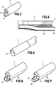
- the apparatus 13 is intended to occupy a retracted position inside the insertion tube 5 as illustrated in FIGS. Fig. 1 and 2 , and a working position as illustrated in Fig. 3 and 4 , for which the apparatus 13 occupies at least a portion of the outlet section 8.
- the apparatus 13 equipping the instrument 1 depends on the nature of the operation or operations to be performed by the endoscope.
- the apparatus 13 corresponds, without limitation, to one or more equipment, tools, sensors, equipment or accessories.
- This apparatus 13 may be of various fields and be of a nature such as mechanical, electrical, heat, magnetic, chemical, fluidic, solid, etc. to perform various operations such as, for example, incisions, destruction, sampling, measurements, supply of a material (gas, liquid, solid).
- the apparatus 13 comprises a tubular duct mounted inside the insertion tube 5, slidably with respect to the tube 5.
- This tubular duct 13 is connected to any appropriate means for ensure the relative sliding of the tubular duct inside the insertion tube 5.
- This tubular duct 13 thus allows to bring to the end of the insertion tube 5 all types of equipment, tools or equipment all kinds. These and other equipment may be attached or mounted inside the insertion tube 5.
- the tubular conduit 13 may be connected to a source of fluid supply at the proximal portion of the instrument and / or incorporating a quantity of fluid and / or material which is intended to be delivered to the distal end of the instrument 1.
- the apparatus 13 may comprise one or more tubes in which the equipment and the like are mounted. Moreover, the apparatus 13 may comprise the equipment and the like mounted directly inside the insertion tube 5, that is to say that the apparatus 13 does not comprise a tubular conduit. In the case where the apparatus 13 comprises several equipment and the like, the latter can leave the distal part 7 by the same orifice 11 or by several orifices 11 of passages 12 communicating with the inside of the insertion tube 5.
- the distal portion 7 of the insertion tube 5 comprises, over part of its length, from the outlet section 8, at least one radially deformable wall 15 making it possible to increase the outlet section 8 of the distal portion of the tube during the passage of at least one apparatus 13 from its retracted position to its working position.
- This deformable wall 15 is made in any appropriate manner to allow radial extension of the distal portion 7 of the tube 5 during the supply of the apparatus 13 to the outlet section 8.
- the transverse cross section of the apparatus 13 is advantageously greater than the transverse cross section of the outlet orifice 11 at rest or in the retracted position of the apparatus 13.
- the retracted position of the apparatus 13 is chosen in upstream of the outlet section 8 at a location not affecting the transverse cross section of the insertion tube 5.
- the retracted position of the apparatus 13 is shown schematically at the entrance of the distal portion 7, but it is clear that this retracted position can correspond to any position inside the instrument 1 or the support 3.
- the deformable wall 15 is made by a portion of the deformable material constituting the distal portion 7 of the insertion tube.
- the distal portion 7 is in the form of a block or sleeve in which the viewing system 10 is embedded.
- the block of material delimits internally a bore to form the passage 12 which communicates with the inside of the tube 5 and opens at the end through the outlet orifice 11.
- the distal portion 7 is therefore in the form of a block of a flexible material in which the display device 10 is embedded and to delimit the passage 12 for the apparatus.
- This distal portion 7 is connected by any appropriate means to the insertion tube 5.
- This distal portion or head 7 is connected to the insertion tube 5 by means of temporary or permanent assembly means.
- the head or distal portion 7 may be removable or not relative to the insertion tube 5.
- This head or distal portion 7 is mounted in the extension of the insertion tube 5 having, in the retracted position of the apparatus 13, a transverse cross section equal to the transverse cross section of the insertion tube 5.
- the radially deformable wall 10 can be made differently.
- This deformable wall 10 may be made for example by a flexible membrane fixed on a rigid body.
- the distal portion 7 constitutes a substantially rigid body equipped with the deformable wall 10.
- This deformable wall 10 may have a deformation which is definitive or temporary when the apparatus 13 returns to its retracted position inside the tube 5 .
- the distortion may come not from a mechanical force as explained above, but for example for heat, ionizing or otherwise.
- the distal portion 7 of the insertion tube 5 comprises a system 19 for guiding the apparatus 13 in order to ensure the radial expansion of the deformable wall 15 during the movement of the apparatus.
- the guide system 19 is in the form of a ramp or a cone opening into the bore 12 for progressively guiding the apparatus 13 to move from its retracted position to its working position.
- the outlet section 8 of the distal portion 7 of the instrument 1 corresponds to the cross section of the insertion tube 5 ( Fig. 1, 2 ).
- the distal portion 7 of the instrument 1 has, in the retracted position of the apparatus 13, a transverse cross section which is equal to the transverse cross section of the insertion tube 5, this distal portion 7 of the instrument 1 having no extra thickness outside the insertion tube 5.
- the insertion tube 5 has a constant cross section along the entire length of its part proximal 6 at its distal portion 7.
- the distal portion 7 occupies a position in which an apparatus 13 must be brought to its outlet section 8, the displacement or sliding of the apparatus 13 relative to the tube 5, leads to a radial deformation of the deformable wall 15 so that the output section 8, the section of the outlet 11 increases ( Fig. 3, 4 ).
- the outlet section 8 of the distal portion 7 of the insertion tube 5 is greater than the outlet section 8 of the distal portion 7 of the insertion tube 5, in the retracted position.
- the insertion tube 5 thus has an outlet section 8 which increases when the apparatus 13 passes from a retracted position to a working position.
- the transverse cross section of the insertion tube 5 is increased over an axial length limited to at most the distal portion 7 of the insertion tube 5.
- the distal portion 7 of the insertion tube 5 which presents cross sectional variation due to the apparatus corresponds to an axial length less than or equal to twice the diameter of the insertion tube 5.
- the distal portion 7 of the insertion tube 5 is provided with a sealing member 21 closing the outlet orifice 11 of the passage for the apparatus.
- This sealing member 21 is an ejectable plug, a tearable membrane, or the like, via the apparatus 13 or a fluid pressure.
- This sealing member 21 thus closes the outlet orifice 11.
- the sliding of the apparatus 13 to ensure its exit at the end of the distal portion 7 leads to the deformation or tearing of the sealing membrane 21 (or the ejection of the sealing plug).
- the supply of a fluid under pressure at the outlet orifice 11 can also ensure the suppression of the sealing member 21.
- the distal portion 7 of the tubular conduit 13 is provided with at least one sealing envelope 23.
- This sealing envelope 23 is tearable by the tool 13 housed inside the tubular conduit 13.
- this envelope of sealing 23 has a resistance greater than the resistance of the sealing member 21 carried by the distal portion 7.
Landscapes
- Health & Medical Sciences (AREA)
- Life Sciences & Earth Sciences (AREA)
- Surgery (AREA)
- Nuclear Medicine, Radiotherapy & Molecular Imaging (AREA)
- Biomedical Technology (AREA)
- Optics & Photonics (AREA)
- Pathology (AREA)
- Radiology & Medical Imaging (AREA)
- Biophysics (AREA)
- Engineering & Computer Science (AREA)
- Physics & Mathematics (AREA)
- Heart & Thoracic Surgery (AREA)
- Medical Informatics (AREA)
- Molecular Biology (AREA)
- Animal Behavior & Ethology (AREA)
- General Health & Medical Sciences (AREA)
- Public Health (AREA)
- Veterinary Medicine (AREA)
- Endoscopes (AREA)
Claims (13)
- Instrument für ein Endoskop, umfassend ein Einführrohr (5) mit einer Längsachse (X), mit einem Querschnitt in Bezug auf diese Längsachse, und mit einem proximalen Teil (6) zur Verbindung mit einem Betätigungshalter und einem distalen Teil (7), der einen Austrittsquerschnitt (8) aufweist, welcher insbesondere einerseits durch einen Anzeigebereich (9) und andererseits durch wenigstens eine Austrittsöffnung (11) eines Durchgangs (12) für wenigstens eine Einrichtung (13) eingenommen ist, die dazu bestimmt ist, eine eingezogene Position innerhalb des Rohres (5) und eine Arbeitsposition einzunehmen, für die die Einrichtung wenigstens einen Teil des Austrittsquerschnitts (8) einnimmt, wobei der distale Teil (7) des Einführrohres auf einem Teil seiner Länge, von dem Austrittsquerschnitt (8) ausgehend, wenigstens eine radial verformbare Wand (15) umfasst, die ermöglicht, den Austrittsquerschnitt des distalen Teils (7) des Rohres (5) beim Übergang der Einrichtung (13) von ihrer eingezogenen Position, in der die Einrichtung die verformbare Wand nicht belastet, in ihre Arbeitsposition, in der die verformbare Wand (15) radial belastet ist, zu vergrößern, wobei der Austrittsquerschnitt (8) des distalen Teils (7) dem Querschnitt des Einführrohres (5) in der eingezogenen Position der Einrichtung (13) entspricht, dadurch gekennzeichnet, dass das Einführrohr (5) in seinem distalen Teil (7) ein System zum Führen (19) der Einrichtung (13) umfasst, das in Form einer Rampe oder eines Konus vorliegt, welche(r) in eine Bohrung mündet, die den Durchgang (12) bildet, um die Einrichtung (13) schrittweise zu führen, damit sie unter Bewirken der radialen Ausdehnung der verformbaren Wand (15) während der Bewegung der Einrichtung von ihrer eingezogenen Position in ihre Arbeitsposition übergeht.
- Medizinisches Instrument nach Anspruch 1, dadurch gekennzeichnet, dass der distale Teil (7) des Einführrohres mit einem Dichtungselement (21) versehen ist, das die Austrittsöffnung (11) des Durchgangs für die Einrichtung (13) verschließt.
- Instrument nach Anspruch 2, dadurch gekennzeichnet, dass das Dichtungselement (21) ein(e) über die Einrichtung oder einen Fluiddruck auswerfbarer Stopfen oder zerreißbare Membran ist.
- Instrument nach einem der Ansprüche 1 bis 3, dadurch gekennzeichnet, dass die Einrichtung (13) wenigstens eine rohrförmige Leitung umfasst, die innerhalb des Einführrohres, gegenüber dem Einführrohr verschieblich, angebracht ist.
- Instrument nach einem der Ansprüche 1 bis 4, dadurch gekennzeichnet, dass die Einrichtung (13) wenigstens ein Werkzeug aufweist, das in der rohrförmigen Leitung angebracht ist oder nicht.
- Instrument nach Anspruch 4 oder 5, dadurch gekennzeichnet, dass der distale Teil (7) der rohrförmigen Leitung (13) mit wenigstens einer Dichtungshülle (23) versehen ist.
- Instrument nach Anspruch 6, dadurch gekennzeichnet, dass die Dichtungshülle (23) einen Widerstand aufweist, der größer ist als der Widerstand des Dichtungselements (21), das von dem distalen Teil (7) des Einführrohres getragen wird.
- Instrument nach Anspruch 5, dadurch gekennzeichnet, dass die Dichtungshülle (23) der rohrförmigen Leitung (13) eine Hülle ist, welche durch das innerhalb der rohrförmigen Leitung (13) aufgenommene Werkzeug zerreißbar ist.
- Instrument nach einem der Ansprüche 1 bis 8, dadurch gekennzeichnet, dass der distale Teil (7) des Einführrohres (5) in ein verformbares Material eingebettet ist, das den Durchgang (12) für die Einrichtung innen begrenzt.
- Instrument nach Anspruch 1, dadurch gekennzeichnet, dass der distale Teil (7) des Einführrohres (5) ein Anzeigesystem (10) umfasst.
- Instrument nach den Ansprüchen 9 und 10, dadurch gekennzeichnet, dass das Anzeigesystem (10) in das verformbare Material eingebettet ist.
- Instrument nach einem der Ansprüche 1 bis 11, dadurch gekennzeichnet, dass der distale Teil (7) gegenüber dem Einführrohr (5) lösbar ist oder nicht.
- Endoskop, dadurch gekennzeichnet, dass es wenigstens ein Instrument (1) gemäß einem der Ansprüche 1 bis 12 umfasst.
Applications Claiming Priority (2)
| Application Number | Priority Date | Filing Date | Title |
|---|---|---|---|
| FR0855854A FR2935252B1 (fr) | 2008-09-01 | 2008-09-01 | Instrument pour endoscope. |
| PCT/FR2009/051649 WO2010023416A2 (fr) | 2008-09-01 | 2009-09-01 | Instrument pour endoscope |
Publications (2)
| Publication Number | Publication Date |
|---|---|
| EP2344018A2 EP2344018A2 (de) | 2011-07-20 |
| EP2344018B1 true EP2344018B1 (de) | 2018-08-01 |
Family
ID=40473623
Family Applications (1)
| Application Number | Title | Priority Date | Filing Date |
|---|---|---|---|
| EP09741347.0A Not-in-force EP2344018B1 (de) | 2008-09-01 | 2009-09-01 | Instrument für ein endoskop |
Country Status (6)
| Country | Link |
|---|---|
| US (1) | US8784298B2 (de) |
| EP (1) | EP2344018B1 (de) |
| CN (1) | CN102137615B (de) |
| DK (1) | DK2344018T3 (de) |
| FR (1) | FR2935252B1 (de) |
| WO (1) | WO2010023416A2 (de) |
Families Citing this family (26)
| Publication number | Priority date | Publication date | Assignee | Title |
|---|---|---|---|---|
| US9427138B2 (en) * | 2011-09-20 | 2016-08-30 | Boston Scientific Scimed, Inc. | Access devices and related methods of use |
| US10265461B2 (en) | 2013-08-29 | 2019-04-23 | Motus Gi Medical Technologies Ltd. | Colon cleaning system with automatic self-purging features |
| WO2015075721A1 (en) | 2013-11-21 | 2015-05-28 | Motus Gi Medical Technologies Ltd. | Distal front end for coordinated positioning of an endoscope with a suction device |
| US9949618B2 (en) | 2013-11-21 | 2018-04-24 | Motus Gi Medical Technologies Ltd. | Apparatus and method for coupling between a colonoscope and add-on tubes |
| WO2015155776A2 (en) | 2014-04-09 | 2015-10-15 | Motus Gi Medical Technologies Ltd. | Cleaning method for prepless colonoscopy |
| JP6253796B2 (ja) * | 2014-06-17 | 2017-12-27 | モータス・ジィ・アイ・メディカル・テクノロジーズ・リミテッドMotus Gi Medical Technologies Ltd. | 結腸内視鏡と追加管との間を結合するための装置および方法 |
| US9913570B2 (en) * | 2015-08-07 | 2018-03-13 | Enlightenvue Llc | Endoscope with variable profile tip |
| CA3016336A1 (en) * | 2016-03-17 | 2017-09-21 | Trice Medical, Inc. | Clot evacuation and visualization devices and methods of use |
| US11096560B2 (en) | 2016-09-23 | 2021-08-24 | Meditrina, Inc. | Endoscope with multiple image sensors |
| US20180160893A1 (en) | 2016-12-12 | 2018-06-14 | Meditrina, Inc. | Endoscope and method of use |
| CN106943114B (zh) * | 2017-04-27 | 2019-01-08 | 泗洪县正心医疗技术有限公司 | 一种末端可扩大的内窥镜 |
| CA3075487A1 (en) | 2017-06-30 | 2019-01-03 | Enlightenvue Llc | Endoscopy systems and methods of use thereof |
| EP3694390B1 (de) * | 2017-10-11 | 2023-12-20 | Meditrina, Inc. | Endoskop |
| US12156640B2 (en) | 2017-10-11 | 2024-12-03 | Meditrina, Inc. | Endoscope and method of use |
| JP2021533895A (ja) | 2018-08-16 | 2021-12-09 | モータス ジーアイ メディカル テクノロジーズ リミテッド | 統合型内視鏡クレンジングシステム |
| WO2020046977A1 (en) | 2018-08-27 | 2020-03-05 | Meditrina, Inc. | Endoscope and method of use |
| US10687698B2 (en) | 2018-09-12 | 2020-06-23 | Enlightenvue Llc | Direct endoluminal- and/or endovascular-illumination systems and methods of use thereof |
| US11517342B2 (en) * | 2018-11-09 | 2022-12-06 | Meditrina, Inc. | Surgical cutting device with gear mechanism |
| BR112021019486A2 (pt) * | 2019-03-29 | 2021-11-30 | Coopersurgical Inc | Dispositivos endoscópicos e métodos relacionados |
| US12575721B2 (en) | 2019-05-01 | 2026-03-17 | Ambu A/S | Devices, systems, and methods for treating kidney stones |
| US11259695B2 (en) | 2020-07-21 | 2022-03-01 | Meditrina, Inc. | Endoscope and method of use |
| CN115067858A (zh) * | 2021-03-11 | 2022-09-20 | 微创优通医疗科技(上海)有限公司 | 内窥镜及内窥镜系统 |
| US20240252027A1 (en) | 2021-05-21 | 2024-08-01 | Ambu A/S | Endoscope with an insertion cord including an interstitial lumen |
| CN115363507B (zh) * | 2022-06-15 | 2024-08-09 | 湖南省华芯医疗器械有限公司 | 一种内窥镜器械管、远端可扩张的插入部、手柄及内窥镜 |
| CN115054185B (zh) * | 2022-06-15 | 2024-04-12 | 湖南省华芯医疗器械有限公司 | 一种内窥镜器械管、远端可扩张的插入部、手柄及内窥镜 |
| WO2024175992A2 (en) * | 2023-02-21 | 2024-08-29 | Suzhou Acuvu Medical Technology Co. Ltd | Endoscope with a flexural distal tip |
Family Cites Families (7)
| Publication number | Priority date | Publication date | Assignee | Title |
|---|---|---|---|---|
| US5257617A (en) * | 1989-12-25 | 1993-11-02 | Asahi Kogaku Kogyo Kabushiki Kaisha | Sheathed endoscope and sheath therefor |
| US5025778A (en) * | 1990-03-26 | 1991-06-25 | Opielab, Inc. | Endoscope with potential channels and method of using the same |
| US5503616A (en) * | 1991-06-10 | 1996-04-02 | Endomedical Technologies, Inc. | Collapsible access channel system |
| US5685822A (en) * | 1996-08-08 | 1997-11-11 | Vision-Sciences, Inc. | Endoscope with sheath retaining device |
| JP2003339624A (ja) * | 2002-05-28 | 2003-12-02 | Pentax Corp | 内視鏡の先端部 |
| EP1659921B1 (de) | 2003-08-04 | 2016-05-11 | Vision-Sciences, Inc. | Schleuse mit kanal für endoskop |
| US8550988B2 (en) * | 2008-04-21 | 2013-10-08 | Covidien Lp | Endoscopic cleaner |
-
2008
- 2008-09-01 FR FR0855854A patent/FR2935252B1/fr not_active Expired - Fee Related
-
2009
- 2009-09-01 CN CN2009801339566A patent/CN102137615B/zh active Active
- 2009-09-01 WO PCT/FR2009/051649 patent/WO2010023416A2/fr not_active Ceased
- 2009-09-01 DK DK09741347.0T patent/DK2344018T3/en active
- 2009-09-01 EP EP09741347.0A patent/EP2344018B1/de not_active Not-in-force
- 2009-09-01 US US13/060,107 patent/US8784298B2/en active Active
Also Published As
| Publication number | Publication date |
|---|---|
| US8784298B2 (en) | 2014-07-22 |
| DK2344018T3 (en) | 2018-11-26 |
| FR2935252B1 (fr) | 2011-03-04 |
| EP2344018A2 (de) | 2011-07-20 |
| WO2010023416A2 (fr) | 2010-03-04 |
| US20110184233A1 (en) | 2011-07-28 |
| CN102137615B (zh) | 2013-11-13 |
| WO2010023416A3 (fr) | 2010-04-22 |
| CN102137615A (zh) | 2011-07-27 |
| FR2935252A1 (fr) | 2010-03-05 |
Similar Documents
| Publication | Publication Date | Title |
|---|---|---|
| WO2010023416A2 (fr) | Instrument pour endoscope | |
| JP6741786B2 (ja) | 内視鏡 | |
| JP6108836B2 (ja) | バルーン内視鏡 | |
| CN103687528B (zh) | 内窥镜 | |
| EP2022387B1 (de) | Endoskop und endoskop-system | |
| JP2020175222A (ja) | 内視鏡用キャップおよび内視鏡 | |
| US20070244361A1 (en) | Balloon unit for endoscope apparatus | |
| WO2013128136A2 (fr) | Dispositif de micro-endoscopie de precision et micro-endoscope associe | |
| CN104822331A (zh) | 用于组织去除的可插入内窥镜器械 | |
| US20110077463A1 (en) | Optical probe and endoscope apparatus | |
| JP7285804B2 (ja) | 内視鏡および内視鏡用キャップの取り外し方法 | |
| EP2432371A1 (de) | Medizinisches instrument mit mehreren funktionen für ein endoskop | |
| FR2765349A1 (fr) | Endoscope | |
| WO2018142838A1 (ja) | 内視鏡用送気送水弁及び内視鏡 | |
| JP6496011B2 (ja) | 内視鏡の組立方法及び内視鏡 | |
| JP7544797B2 (ja) | 介入医療装置用圧力センサモジュール | |
| JP3422213B2 (ja) | 内視鏡ガイド装置 | |
| EP4003137A1 (de) | Übertubus und medizinprodukt mit diesem übertubus | |
| WO2021144512A1 (fr) | Endoscope pourvu d'un dispositif d'obturation d'un circuit de circulation d'un fluide, pour une sterilisation amelioree | |
| FR3106268A1 (fr) | Tête distale pour endoscope pourvue d’un canal de travail élargi | |
| CN221635707U (zh) | 一种内镜器械通道封闭装置 | |
| WO2022144303A1 (fr) | Surtube et dispositif médical utilisant ce surtube | |
| KR20230035538A (ko) | 내시경 캡 | |
| JP2004129720A (ja) | 内視鏡装置 | |
| FR3120776A1 (fr) | Système de suture endoscopique et dispositif médical utilisant ce système. |
Legal Events
| Date | Code | Title | Description |
|---|---|---|---|
| PUAI | Public reference made under article 153(3) epc to a published international application that has entered the european phase |
Free format text: ORIGINAL CODE: 0009012 |
|
| 17P | Request for examination filed |
Effective date: 20110223 |
|
| AK | Designated contracting states |
Kind code of ref document: A2 Designated state(s): AT BE BG CH CY CZ DE DK EE ES FI FR GB GR HR HU IE IS IT LI LT LU LV MC MK MT NL NO PL PT RO SE SI SK SM TR |
|
| AX | Request for extension of the european patent |
Extension state: AL BA RS |
|
| DAX | Request for extension of the european patent (deleted) | ||
| 17Q | First examination report despatched |
Effective date: 20160219 |
|
| REG | Reference to a national code |
Ref country code: DE Ref legal event code: R079 Ref document number: 602009053581 Country of ref document: DE Free format text: PREVIOUS MAIN CLASS: A61B0001012000 Ipc: A61B0001000000 |
|
| GRAP | Despatch of communication of intention to grant a patent |
Free format text: ORIGINAL CODE: EPIDOSNIGR1 |
|
| RIC1 | Information provided on ipc code assigned before grant |
Ipc: A61B 1/018 20060101ALI20180201BHEP Ipc: A61B 1/00 20060101AFI20180201BHEP |
|
| INTG | Intention to grant announced |
Effective date: 20180305 |
|
| RIN1 | Information on inventor provided before grant (corrected) |
Inventor name: MATHIEU, NICOLAS Inventor name: FRUCTUS, OLIVIER |
|
| GRAS | Grant fee paid |
Free format text: ORIGINAL CODE: EPIDOSNIGR3 |
|
| GRAA | (expected) grant |
Free format text: ORIGINAL CODE: 0009210 |
|
| AK | Designated contracting states |
Kind code of ref document: B1 Designated state(s): AT BE BG CH CY CZ DE DK EE ES FI FR GB GR HR HU IE IS IT LI LT LU LV MC MK MT NL NO PL PT RO SE SI SK SM TR |
|
| REG | Reference to a national code |
Ref country code: GB Ref legal event code: FG4D Free format text: NOT ENGLISH |
|
| REG | Reference to a national code |
Ref country code: CH Ref legal event code: EP Ref country code: AT Ref legal event code: REF Ref document number: 1023336 Country of ref document: AT Kind code of ref document: T Effective date: 20180815 |
|
| REG | Reference to a national code |
Ref country code: IE Ref legal event code: FG4D Free format text: LANGUAGE OF EP DOCUMENT: FRENCH |
|
| REG | Reference to a national code |
Ref country code: DE Ref legal event code: R096 Ref document number: 602009053581 Country of ref document: DE |
|
| REG | Reference to a national code |
Ref country code: FR Ref legal event code: PLFP Year of fee payment: 10 |
|
| REG | Reference to a national code |
Ref country code: DK Ref legal event code: T3 Effective date: 20181119 |
|
| REG | Reference to a national code |
Ref country code: NL Ref legal event code: MP Effective date: 20180801 |
|
| REG | Reference to a national code |
Ref country code: LT Ref legal event code: MG4D |
|
| REG | Reference to a national code |
Ref country code: AT Ref legal event code: MK05 Ref document number: 1023336 Country of ref document: AT Kind code of ref document: T Effective date: 20180801 |
|
| PG25 | Lapsed in a contracting state [announced via postgrant information from national office to epo] |
Ref country code: FI Free format text: LAPSE BECAUSE OF FAILURE TO SUBMIT A TRANSLATION OF THE DESCRIPTION OR TO PAY THE FEE WITHIN THE PRESCRIBED TIME-LIMIT Effective date: 20180801 Ref country code: PL Free format text: LAPSE BECAUSE OF FAILURE TO SUBMIT A TRANSLATION OF THE DESCRIPTION OR TO PAY THE FEE WITHIN THE PRESCRIBED TIME-LIMIT Effective date: 20180801 Ref country code: SE Free format text: LAPSE BECAUSE OF FAILURE TO SUBMIT A TRANSLATION OF THE DESCRIPTION OR TO PAY THE FEE WITHIN THE PRESCRIBED TIME-LIMIT Effective date: 20180801 Ref country code: AT Free format text: LAPSE BECAUSE OF FAILURE TO SUBMIT A TRANSLATION OF THE DESCRIPTION OR TO PAY THE FEE WITHIN THE PRESCRIBED TIME-LIMIT Effective date: 20180801 Ref country code: NL Free format text: LAPSE BECAUSE OF FAILURE TO SUBMIT A TRANSLATION OF THE DESCRIPTION OR TO PAY THE FEE WITHIN THE PRESCRIBED TIME-LIMIT Effective date: 20180801 Ref country code: NO Free format text: LAPSE BECAUSE OF FAILURE TO SUBMIT A TRANSLATION OF THE DESCRIPTION OR TO PAY THE FEE WITHIN THE PRESCRIBED TIME-LIMIT Effective date: 20181101 Ref country code: BG Free format text: LAPSE BECAUSE OF FAILURE TO SUBMIT A TRANSLATION OF THE DESCRIPTION OR TO PAY THE FEE WITHIN THE PRESCRIBED TIME-LIMIT Effective date: 20181101 Ref country code: LT Free format text: LAPSE BECAUSE OF FAILURE TO SUBMIT A TRANSLATION OF THE DESCRIPTION OR TO PAY THE FEE WITHIN THE PRESCRIBED TIME-LIMIT Effective date: 20180801 Ref country code: GR Free format text: LAPSE BECAUSE OF FAILURE TO SUBMIT A TRANSLATION OF THE DESCRIPTION OR TO PAY THE FEE WITHIN THE PRESCRIBED TIME-LIMIT Effective date: 20181102 Ref country code: IS Free format text: LAPSE BECAUSE OF FAILURE TO SUBMIT A TRANSLATION OF THE DESCRIPTION OR TO PAY THE FEE WITHIN THE PRESCRIBED TIME-LIMIT Effective date: 20181201 |
|
| PG25 | Lapsed in a contracting state [announced via postgrant information from national office to epo] |
Ref country code: HR Free format text: LAPSE BECAUSE OF FAILURE TO SUBMIT A TRANSLATION OF THE DESCRIPTION OR TO PAY THE FEE WITHIN THE PRESCRIBED TIME-LIMIT Effective date: 20180801 Ref country code: ES Free format text: LAPSE BECAUSE OF FAILURE TO SUBMIT A TRANSLATION OF THE DESCRIPTION OR TO PAY THE FEE WITHIN THE PRESCRIBED TIME-LIMIT Effective date: 20180801 Ref country code: LV Free format text: LAPSE BECAUSE OF FAILURE TO SUBMIT A TRANSLATION OF THE DESCRIPTION OR TO PAY THE FEE WITHIN THE PRESCRIBED TIME-LIMIT Effective date: 20180801 |
|
| PG25 | Lapsed in a contracting state [announced via postgrant information from national office to epo] |
Ref country code: MC Free format text: LAPSE BECAUSE OF FAILURE TO SUBMIT A TRANSLATION OF THE DESCRIPTION OR TO PAY THE FEE WITHIN THE PRESCRIBED TIME-LIMIT Effective date: 20180801 Ref country code: CZ Free format text: LAPSE BECAUSE OF FAILURE TO SUBMIT A TRANSLATION OF THE DESCRIPTION OR TO PAY THE FEE WITHIN THE PRESCRIBED TIME-LIMIT Effective date: 20180801 Ref country code: EE Free format text: LAPSE BECAUSE OF FAILURE TO SUBMIT A TRANSLATION OF THE DESCRIPTION OR TO PAY THE FEE WITHIN THE PRESCRIBED TIME-LIMIT Effective date: 20180801 Ref country code: RO Free format text: LAPSE BECAUSE OF FAILURE TO SUBMIT A TRANSLATION OF THE DESCRIPTION OR TO PAY THE FEE WITHIN THE PRESCRIBED TIME-LIMIT Effective date: 20180801 Ref country code: IT Free format text: LAPSE BECAUSE OF FAILURE TO SUBMIT A TRANSLATION OF THE DESCRIPTION OR TO PAY THE FEE WITHIN THE PRESCRIBED TIME-LIMIT Effective date: 20180801 |
|
| REG | Reference to a national code |
Ref country code: CH Ref legal event code: PL |
|
| REG | Reference to a national code |
Ref country code: DE Ref legal event code: R097 Ref document number: 602009053581 Country of ref document: DE |
|
| PG25 | Lapsed in a contracting state [announced via postgrant information from national office to epo] |
Ref country code: SK Free format text: LAPSE BECAUSE OF FAILURE TO SUBMIT A TRANSLATION OF THE DESCRIPTION OR TO PAY THE FEE WITHIN THE PRESCRIBED TIME-LIMIT Effective date: 20180801 Ref country code: SM Free format text: LAPSE BECAUSE OF FAILURE TO SUBMIT A TRANSLATION OF THE DESCRIPTION OR TO PAY THE FEE WITHIN THE PRESCRIBED TIME-LIMIT Effective date: 20180801 |
|
| PLBE | No opposition filed within time limit |
Free format text: ORIGINAL CODE: 0009261 |
|
| STAA | Information on the status of an ep patent application or granted ep patent |
Free format text: STATUS: NO OPPOSITION FILED WITHIN TIME LIMIT |
|
| REG | Reference to a national code |
Ref country code: BE Ref legal event code: MM Effective date: 20180930 |
|
| REG | Reference to a national code |
Ref country code: IE Ref legal event code: MM4A |
|
| PG25 | Lapsed in a contracting state [announced via postgrant information from national office to epo] |
Ref country code: LU Free format text: LAPSE BECAUSE OF NON-PAYMENT OF DUE FEES Effective date: 20180901 |
|
| 26N | No opposition filed |
Effective date: 20190503 |
|
| PG25 | Lapsed in a contracting state [announced via postgrant information from national office to epo] |
Ref country code: IE Free format text: LAPSE BECAUSE OF NON-PAYMENT OF DUE FEES Effective date: 20180901 |
|
| PG25 | Lapsed in a contracting state [announced via postgrant information from national office to epo] |
Ref country code: BE Free format text: LAPSE BECAUSE OF NON-PAYMENT OF DUE FEES Effective date: 20180930 Ref country code: SI Free format text: LAPSE BECAUSE OF FAILURE TO SUBMIT A TRANSLATION OF THE DESCRIPTION OR TO PAY THE FEE WITHIN THE PRESCRIBED TIME-LIMIT Effective date: 20180801 Ref country code: LI Free format text: LAPSE BECAUSE OF NON-PAYMENT OF DUE FEES Effective date: 20180930 Ref country code: CH Free format text: LAPSE BECAUSE OF NON-PAYMENT OF DUE FEES Effective date: 20180930 |
|
| PG25 | Lapsed in a contracting state [announced via postgrant information from national office to epo] |
Ref country code: MT Free format text: LAPSE BECAUSE OF FAILURE TO SUBMIT A TRANSLATION OF THE DESCRIPTION OR TO PAY THE FEE WITHIN THE PRESCRIBED TIME-LIMIT Effective date: 20180801 |
|
| PG25 | Lapsed in a contracting state [announced via postgrant information from national office to epo] |
Ref country code: TR Free format text: LAPSE BECAUSE OF FAILURE TO SUBMIT A TRANSLATION OF THE DESCRIPTION OR TO PAY THE FEE WITHIN THE PRESCRIBED TIME-LIMIT Effective date: 20180801 |
|
| PG25 | Lapsed in a contracting state [announced via postgrant information from national office to epo] |
Ref country code: HU Free format text: LAPSE BECAUSE OF FAILURE TO SUBMIT A TRANSLATION OF THE DESCRIPTION OR TO PAY THE FEE WITHIN THE PRESCRIBED TIME-LIMIT; INVALID AB INITIO Effective date: 20090901 Ref country code: PT Free format text: LAPSE BECAUSE OF FAILURE TO SUBMIT A TRANSLATION OF THE DESCRIPTION OR TO PAY THE FEE WITHIN THE PRESCRIBED TIME-LIMIT Effective date: 20180801 |
|
| PG25 | Lapsed in a contracting state [announced via postgrant information from national office to epo] |
Ref country code: MK Free format text: LAPSE BECAUSE OF NON-PAYMENT OF DUE FEES Effective date: 20180801 Ref country code: CY Free format text: LAPSE BECAUSE OF FAILURE TO SUBMIT A TRANSLATION OF THE DESCRIPTION OR TO PAY THE FEE WITHIN THE PRESCRIBED TIME-LIMIT Effective date: 20180801 |
|
| REG | Reference to a national code |
Ref country code: DE Ref legal event code: R082 Ref document number: 602009053581 Country of ref document: DE Representative=s name: CBDL PATENTANWAELTE GBR, DE |
|
| PGFP | Annual fee paid to national office [announced via postgrant information from national office to epo] |
Ref country code: FR Payment date: 20230920 Year of fee payment: 15 Ref country code: DK Payment date: 20230921 Year of fee payment: 15 |
|
| PGFP | Annual fee paid to national office [announced via postgrant information from national office to epo] |
Ref country code: GB Payment date: 20231019 Year of fee payment: 15 |
|
| PGFP | Annual fee paid to national office [announced via postgrant information from national office to epo] |
Ref country code: DE Payment date: 20231011 Year of fee payment: 15 |
|
| REG | Reference to a national code |
Ref country code: DE Ref legal event code: R119 Ref document number: 602009053581 Country of ref document: DE |
|
| REG | Reference to a national code |
Ref country code: DK Ref legal event code: EBP Effective date: 20240930 |
|
| GBPC | Gb: european patent ceased through non-payment of renewal fee |
Effective date: 20240901 |
|
| PG25 | Lapsed in a contracting state [announced via postgrant information from national office to epo] |
Ref country code: DE Free format text: LAPSE BECAUSE OF NON-PAYMENT OF DUE FEES Effective date: 20250401 |
|
| PG25 | Lapsed in a contracting state [announced via postgrant information from national office to epo] |
Ref country code: GB Free format text: LAPSE BECAUSE OF NON-PAYMENT OF DUE FEES Effective date: 20240901 |
|
| PG25 | Lapsed in a contracting state [announced via postgrant information from national office to epo] |
Ref country code: FR Free format text: LAPSE BECAUSE OF NON-PAYMENT OF DUE FEES Effective date: 20240930 |
|
| PG25 | Lapsed in a contracting state [announced via postgrant information from national office to epo] |
Ref country code: DK Free format text: LAPSE BECAUSE OF NON-PAYMENT OF DUE FEES Effective date: 20240930 |