EP2344773B1 - Druckreglervorrichtung, insbesondere der hydraulischen fernsteuerungsart - Google Patents
Druckreglervorrichtung, insbesondere der hydraulischen fernsteuerungsart Download PDFInfo
- Publication number
- EP2344773B1 EP2344773B1 EP20090760165 EP09760165A EP2344773B1 EP 2344773 B1 EP2344773 B1 EP 2344773B1 EP 20090760165 EP20090760165 EP 20090760165 EP 09760165 A EP09760165 A EP 09760165A EP 2344773 B1 EP2344773 B1 EP 2344773B1
- Authority
- EP
- European Patent Office
- Prior art keywords
- damping
- control
- cavity
- pistons
- push
- Prior art date
- Legal status (The legal status is an assumption and is not a legal conclusion. Google has not performed a legal analysis and makes no representation as to the accuracy of the status listed.)
- Not-in-force
Links
- 238000013016 damping Methods 0.000 claims description 129
- 230000002093 peripheral effect Effects 0.000 claims description 38
- 238000004891 communication Methods 0.000 claims description 35
- 239000003638 chemical reducing agent Substances 0.000 claims description 30
- 239000012530 fluid Substances 0.000 claims description 30
- 230000001105 regulatory effect Effects 0.000 claims description 19
- 230000033001 locomotion Effects 0.000 claims description 13
- 238000013519 translation Methods 0.000 claims description 12
- 230000003042 antagnostic effect Effects 0.000 claims description 6
- 230000000694 effects Effects 0.000 claims description 3
- 208000031968 Cadaver Diseases 0.000 description 20
- 235000021183 entrée Nutrition 0.000 description 8
- 238000003754 machining Methods 0.000 description 5
- 238000006073 displacement reaction Methods 0.000 description 4
- 230000009471 action Effects 0.000 description 2
- 239000005557 antagonist Substances 0.000 description 2
- 238000013459 approach Methods 0.000 description 2
- 230000033228 biological regulation Effects 0.000 description 2
- 238000010276 construction Methods 0.000 description 2
- 230000010354 integration Effects 0.000 description 2
- 238000007789 sealing Methods 0.000 description 2
- 230000001276 controlling effect Effects 0.000 description 1
- 230000007423 decrease Effects 0.000 description 1
- 238000002513 implantation Methods 0.000 description 1
- 238000000034 method Methods 0.000 description 1
- 230000009467 reduction Effects 0.000 description 1
- 230000000284 resting effect Effects 0.000 description 1
Images




Classifications
-
- F—MECHANICAL ENGINEERING; LIGHTING; HEATING; WEAPONS; BLASTING
- F15—FLUID-PRESSURE ACTUATORS; HYDRAULICS OR PNEUMATICS IN GENERAL
- F15B—SYSTEMS ACTING BY MEANS OF FLUIDS IN GENERAL; FLUID-PRESSURE ACTUATORS, e.g. SERVOMOTORS; DETAILS OF FLUID-PRESSURE SYSTEMS, NOT OTHERWISE PROVIDED FOR
- F15B13/00—Details of servomotor systems ; Valves for servomotor systems
- F15B13/02—Fluid distribution or supply devices characterised by their adaptation to the control of servomotors
- F15B13/04—Fluid distribution or supply devices characterised by their adaptation to the control of servomotors for use with a single servomotor
- F15B13/042—Fluid distribution or supply devices characterised by their adaptation to the control of servomotors for use with a single servomotor operated by fluid pressure
- F15B13/0422—Fluid distribution or supply devices characterised by their adaptation to the control of servomotors for use with a single servomotor operated by fluid pressure with manually-operated pilot valves, e.g. joysticks
-
- Y—GENERAL TAGGING OF NEW TECHNOLOGICAL DEVELOPMENTS; GENERAL TAGGING OF CROSS-SECTIONAL TECHNOLOGIES SPANNING OVER SEVERAL SECTIONS OF THE IPC; TECHNICAL SUBJECTS COVERED BY FORMER USPC CROSS-REFERENCE ART COLLECTIONS [XRACs] AND DIGESTS
- Y10—TECHNICAL SUBJECTS COVERED BY FORMER USPC
- Y10T—TECHNICAL SUBJECTS COVERED BY FORMER US CLASSIFICATION
- Y10T137/00—Fluid handling
- Y10T137/2278—Pressure modulating relays or followers
-
- Y—GENERAL TAGGING OF NEW TECHNOLOGICAL DEVELOPMENTS; GENERAL TAGGING OF CROSS-SECTIONAL TECHNOLOGIES SPANNING OVER SEVERAL SECTIONS OF THE IPC; TECHNICAL SUBJECTS COVERED BY FORMER USPC CROSS-REFERENCE ART COLLECTIONS [XRACs] AND DIGESTS
- Y10—TECHNICAL SUBJECTS COVERED BY FORMER USPC
- Y10T—TECHNICAL SUBJECTS COVERED BY FORMER US CLASSIFICATION
- Y10T137/00—Fluid handling
- Y10T137/8593—Systems
- Y10T137/87056—With selective motion for plural valve actuator
-
- Y—GENERAL TAGGING OF NEW TECHNOLOGICAL DEVELOPMENTS; GENERAL TAGGING OF CROSS-SECTIONAL TECHNOLOGIES SPANNING OVER SEVERAL SECTIONS OF THE IPC; TECHNICAL SUBJECTS COVERED BY FORMER USPC CROSS-REFERENCE ART COLLECTIONS [XRACs] AND DIGESTS
- Y10—TECHNICAL SUBJECTS COVERED BY FORMER USPC
- Y10T—TECHNICAL SUBJECTS COVERED BY FORMER US CLASSIFICATION
- Y10T137/00—Fluid handling
- Y10T137/8593—Systems
- Y10T137/87056—With selective motion for plural valve actuator
- Y10T137/87064—Oppositely movable cam surfaces
-
- Y—GENERAL TAGGING OF NEW TECHNOLOGICAL DEVELOPMENTS; GENERAL TAGGING OF CROSS-SECTIONAL TECHNOLOGIES SPANNING OVER SEVERAL SECTIONS OF THE IPC; TECHNICAL SUBJECTS COVERED BY FORMER USPC CROSS-REFERENCE ART COLLECTIONS [XRACs] AND DIGESTS
- Y10—TECHNICAL SUBJECTS COVERED BY FORMER USPC
- Y10T—TECHNICAL SUBJECTS COVERED BY FORMER US CLASSIFICATION
- Y10T137/00—Fluid handling
- Y10T137/8593—Systems
- Y10T137/87169—Supply and exhaust
-
- Y—GENERAL TAGGING OF NEW TECHNOLOGICAL DEVELOPMENTS; GENERAL TAGGING OF CROSS-SECTIONAL TECHNOLOGIES SPANNING OVER SEVERAL SECTIONS OF THE IPC; TECHNICAL SUBJECTS COVERED BY FORMER USPC CROSS-REFERENCE ART COLLECTIONS [XRACs] AND DIGESTS
- Y10—TECHNICAL SUBJECTS COVERED BY FORMER USPC
- Y10T—TECHNICAL SUBJECTS COVERED BY FORMER US CLASSIFICATION
- Y10T137/00—Fluid handling
- Y10T137/8593—Systems
- Y10T137/87169—Supply and exhaust
- Y10T137/87233—Biased exhaust valve
- Y10T137/87241—Biased closed
Definitions
- the present invention relates to a pressure regulating device, in particular of the hydraulic remote control type such as a hydraulic remote control for a public works machine.
- These regulation devices are used in particular to control different hydraulic functions such as the setting in motion of different receivers installed aboard these construction machines.
- control member is in the form of a lever or a handle, operable manually, extended by a lower cup disposed facing the upper face of the body of the regulating device; upper face in which opens the control cavities in which are mounted movable control pushers, so that said control pushers protrude from the upper face to abut against the lower cup of the control member.
- control cavities normally extend towards the upper face of the body so that, once said body is fixed on a horizontal floor, the control cavities and the control pushers extend. vertically and the body must have a height adapted to the integration of the pressure reducer. The height of the body leads to a limitation of the height and a vertical space sometimes unacceptable when it comes to implement the control device in a confined space such as a driving cab of a public works machine .
- control cavities are made by machining and are therefore generally made in the form of a hole traversing the body from side to side in the direction of the height, between the lower and upper faces.
- Such an embodiment requires the control cavities to be connected via the lower faces, and thus to bring connection pipes through the horizontal floor on which the regulating device is laid flat, thus hindering the integration of the pipes and the device. complete on the floor.
- transverse bores to the control cavities, making the realization of the body and its various cavities or conduits all the more complex.
- control member is in the form of a tilting pedal, operable at the foot, and arranged facing the upper face of the body of the regulating device.
- a pedal can be used in construction machinery for control of forward and backward of the machine, in other words for moving back and forth or the translation of the machine.
- these control devices comprise control cavities and control pushers extending vertically with the same disadvantages as those mentioned above.
- an additional control lever is articulated on one end of the pedal and extends upwards to end with a handle that can be manipulated by hand to add control of the tilting of the pedal.
- a control lever is used to impose a tilting of the pedal from front to back, or conversely, which is more accurate than that obtained directly with the foot on the pedal, in particular to allow a more precise displacement of the public works machine.
- Such a control lever represents a mass located at one end of the pedal, so eccentric with respect to the articulation of the pedal, whose inertia must be fought by means of a damper.
- a damper mounted in the body and comprising two damping pushers arranged on either side of the articulation of the control member (here the pedal) and housed in movement of back and forth in a damping cavity provided in the body, said damper being intended to damp the tilting of the control member in one direction and the other, said control member pushing on the one hand the one of said damping pushers when it switches in one direction and the other of said damping pushers when it switches in the other direction.
- this damper is adapted to damp the tilting of the pedal, and in particular the tilts imposed by a control lever during the movement of the public works machine.
- the damping cavity has a general shape of "U" with two vertical portions extending normally vis-à-vis the upper face of the body and in which move the respective dampers amortization, and a central part connecting the vertical parts and provided with one or more damping pistons.
- the damping pushers extend normally vis-à-vis the upper face of the body so that, once the body fixed on a horizontal floor, the damping pushers extend vertically with the same disadvantages as those mentioned above for the control pushers.
- such a damping cavity is difficult to achieve, at least by simple machining, because of its complex shape "U".
- control and damping cavities do not extend normally to the upper face of the body, and thus vertically once the device is laid flat on a horizontal floor, thus helping to limit the vertical space requirement. of the device and to obtain a saving of height space.
- control and / or damping cavities may extend parallel to the upper face of the body, and thus horizontally once the device is laid flat on a horizontal floor.
- control and damping cavities may not open into the lower face so that it is not necessary to connect the connecting pipes to said lower fax machines, thus facilitating the implantation. said pipes at the floor of the machine.
- the regulating device comprises a single rectilinear damping cavity passing right through the body and opening at its two ends on its peripheral face.
- the at least one control cavity is rectilinear and extends substantially parallel or inclined with respect to the damping cavity.
- this control cavity is simple to perform by machining.
- the damping cavity and the at least one control cavity extend in substantially parallel planes.
- the damper comprises a damping slide-mounted slide with adjustment in the damping cavity
- the damping cavity comprises two working chambers, with variable volume in opposite directions, extending between the two opposite ends of said damping spool and immobilized guide sleeves at the open ends of the damping cavity to guide in translation the respective damping pushers, said working chambers containing a fluid intended to pass from to one another by at least one communication passage under the effect of the thrust of one or the other damping pushers on said damping slide.
- the damping slide is mounted in a simple manner between the two damping pushers, allowing to have a linear damper comprising these three parts successively aligned one after the other.
- the communication passage comprises at least one restriction zone adapted to generate a pressure drop. in said communication passage when flowing fluid passes between the two working chambers.
- This communication passage is carried out either in the damping slide or in the body.
- the damping spool comprises, at its two respective ends, two respective end pistons sliding in the damping cavity, interconnected by a central rod, and against which the respective damping pushers are in position. stop, and wherein the communication passage between the two working chambers is formed in the damping slide between the two said end pistons.
- damping pushers mounted back to back or antagonist, abut against both ends of the damping slide.
- the communication passage comprises two end channels formed in said end pistons and a central channel formed axially in the central connecting rod between the two end pistons, said end channels putting in communication fluid the respective working chambers and the central channel.
- the central channel passes through the two end pistons from one side to the other, in which the damping push rods are sized to close off the respective outlet ends of the central channel, and in which the end channels are under the forming grooves on the end faces of the respective end pistons and fluidly communicating the respective working chambers and the respective through-ends of the central channel.
- the grooves have a generally spiral shape adapted to form a constriction in the flow of fluid between the respective working chambers and the central channel.
- the central channel is internally provided with two opposing jet nozzles designed to generate pressure drops in the flow of fluid within said central channel.
- the dispensing spool comprises two intermediate pistons sliding in the damping cavity and arranged around the central rod between the end pistons, so that the distribution spool internally delimits three internal chambers with constant volume. , namely two internal chambers lateral members disposed between the end pistons and the adjacent intermediate pistons, and a central inner chamber disposed between the two intermediate pistons.
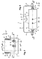
- a regulating device according to the invention is described below with reference to Figures 1 to 8 which more particularly illustrate a control device designed for a foot hydraulic remote control, hydraulic pedal type, intended for example to control the translation of a public works machine.
- the regulating device is intended to be laid flat on a horizontal floor, that is to say a floor parallel to the plane (X, Y), and fixed on the latter.
- the regulating device comprises a body 1 in which is housed two pressure reducers 2 and a damper 3, and on which a control member 4 is installed. This control member 4 is able to modify the pressure regulated by the pressure reducers 2 described below.
- the body 1 is provided with two end faces, namely a lower face 10 and an upper face 11, as well as a peripheral face 12, or lateral face, extending between the two end faces 10, 11
- the end faces 10, 11 extend in a horizontal plane, while the peripheral face 12 extends vertically and forms the periphery of the body 1.
- the body 1 is here of generally parallelepipedal shape with end faces 10, 11 rectangular and a peripheral face 12 having facets also rectangular.
- the base 40 has two flaps 43 projecting normally to the base 40, where said flaps 43 are parallel to the plane (X, Z) vertical and spaced from each other according to the transverse direction Y to support the hinge axis 42 transverse.
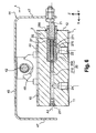
- the damping cavity 30 is in the form of a bore of constant diameter over a part of its length and centered about an axis A3 parallel to the longitudinal direction X; said damping cavity 30 being obtained by a conventional machining technique and easy to implement.
- the control cavities 20 are in the form of two successive bores of different diameter and centered around an axis A1 or A2 parallel to the longitudinal direction X.
- the fluid flowing in the inlet pipe 23 and the fluid circulating in the compensation chamber 200 (and also in the return pipe 22) are respectively qualified high pressure and low pressure relative to each other, independently of any absolute value of pressure.
- the plunger 25 consists essentially of a rod extending between an enlarged head turned towards the control member 4 and a connecting leg turned towards the dispensing channel 210.
- the connecting foot of the plunger 25 is mounted integral in translation with a first end of the dispensing spool 26; the second end of said slide 26 corresponding to its free end into which the axial channel 260 opens.
- Each reducer 2 further comprises a cup 27 mounted coaxially with the rod of the plunger 25 bearing against the lower part of the enlarged head of said plunger 25 to be elastically urged by means of a first return spring 270 against the plunger 25. control 21.
- the first return spring 270 is interposed between the cup 27 and a shoulder defined in the control cavity 20, to push the cup 27 towards the control pusher 21.
- the gearbox 2 optionally comprises a second return spring 271, called the setting or regulation spring, disposed inside the first return spring 270 and interposed between a shoulder of the plunger 25 and the cup 27.
- a second return spring 271 called the setting or regulation spring
- each control pusher 21 is provided by a guide sleeve 28 immobilized at the open end of the compensation chamber 200 in the peripheral face 12 of the body 1; said guide sleeve 28 being immobilized by means of a closure plate 280 fixed to the peripheral face 12 of the body 1, in particular by means of a screw 281.
- Two peripheral grooves are formed in each guide sleeve 28, respectively at the of the inner surface and the outer surface of said sleeve 28, to accommodate seals for sealing between the control pusher 21 and respectively the sleeve 28 and the body 1.
- control cavities 20, and more particularly the compensation chambers 200 open into the peripheral face 12 of the body 1, so that the control pushers 21 project partially out of the peripheral face. 12 of the body 1 to bear against the respective laterally folded portions 47 of the pedal 44.
- one of the control pushers 21 protrudes out of the body 1 to bear against one of the parts laterally folded 47, while the other of the control pushers 21 protrudes out of the body 1 to bear against the other side laterally folded 47.
- the control pushers 21 move in an antagonistic manner, or in reverse in the longitudinal direction X, under the action of the control member 4.
- the laterally folded portions 47 each support a finger 52 designed to bear against the respective control pusher 21; said finger 52 being in the form of a screw whose head offers a bearing surface, slightly rounded, for the control pusher 21 corresponding, and whose free end cooperates with a nut for fixing on the laterally folded 47 corresponding.
- each damping pusher 31 is provided by a guide sleeve 38 immobilized at the open ends of the damping chamber 30 in the peripheral face 12 of the body 1; said guide sleeve 38 being immobilized by means of the aforesaid closing plate 280 which is fixed on the peripheral face 12 of the body 1.
- Two peripheral grooves are formed in each guide sleeve 38, respectively at the inner surface and the outer surface of said sleeve 38, to accommodate seals to ensure sealing between the damping pushers 31 and respectively the respective sleeves 38 and the body 1.
- the damping cavity 30 thus comprises two working chambers 300, of variable volume in opposite directions (that is, the volumes of which vary in an antagonistic manner), extending between the two opposite end pistons 33 and the guide sleeves 38. adjacent; said working chambers 300 containing a fluid for passing from one to the other by at least one communication passage under the effect of the thrust of one or the other damping pushers 31 on the one or other of the end pistons 33 of the damping slide 32.
- the damping cavity 30 opens at its two ends in the peripheral face 12 of the body 1, so that the damping pushers 31 partially project out of the peripheral face 12 of the body 1 in order to bear against the respective laterally folded portions 47 of the pedal 44.
- one of the damping pushers 31 protrudes out of the body 1 to bear against one of the laterally folded parts 47, while the other of the damping pushers 31 protrudes out of the body 1 to bear against the other of the laterally folded parts 47.
- the damping pushers 31 move in an antagonistic manner, or in the opposite direction in the longitudinal direction X, under the action of the control member 4.
- each laterally folded portion 47 each support a finger 53 designed to bear against the respective damping pusher 31; said finger 53 is in the form of a screw whose head offers a bearing surface, slightly rounded, for the damping pusher 31 corresponding, and whose free end cooperates with a nut for fixing on the part laterally folded 47 corresponding.
- each laterally folded portion 47 supports two fingers 52, 53 side by side and extending in a longitudinal plane.
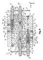
- the damping slide 32 comprises a central channel 340 longitudinal (or axial) formed in the central rod 34; said central channel 340 traversing the central rod 34 over its entire length and also passing through the two end pistons 33 so that said central channel 340 has two ends 341 opening in the end pistons 33.
- the central channel 340 is further provided internally two antagonistic jets 342 designed to generate pressure drops in the flow of fluid within said central channel 340; said nozzles 342 are formed substantially inside the end pistons 33.
- the damping slide 32 comprises two radial channels 344 formed in the central rod 34 and placing the central channel 340 in communication with the respective internal lateral chambers 321; said radial channels 344 being disposed between the two nozzles 342 and opening into the respective internal lateral chambers 321 and in the central channel 340.
- the damping slide 32 includes two end channels 343 in said end pistons 33 for fluid communication between the respective working chambers 300 and the central channel 340.
- the end channels 343 are made in the form of grooves formed on the end faces of the respective end pistons 33, corresponding to the end faces of the damping spool partially delimiting the working chambers 300, and placing in fluid communication said working chambers 300 respective and the respective emergent ends 341 of the central channel 34.
- the damping pushers 31 are dimensioned to close off the respective outlet ends 341 of the central channel 34 so that, during the displacement of the damping pushers 31, the fluid circulates between the working chambers 300 and the central channel 34 via the grooves 343 respective, and not directly in the open ends 341 which are plugged.
- the grooves 343 have a generally adapted spiral shape to form a constriction in the flow of fluid between the respective working chambers 300 and the central channel 34, to participate in the desired damping of the displacement of the damping pushers 31.
- the spiral grooves 343 thus have a first end sufficiently far from the axis A3 not to be closed by the corresponding damping pusher 31, and a second end opening into the respective through end 341 of the central channel 34.
- the fluid passage between the two working chambers 300 includes the grooves 343 and the central channel 345, with four restriction zones in the fluid flow, namely the two nozzles 342 and the two spiral grooves 343.
- the inlet ducts 23 of the gearboxes 2 open into the central internal chamber 320 of the damping spool 32.
- the inlet ducts 23 of the two reducers 2 are made in the form of a single bore passing through the body 1 from side to side in the transverse direction Y.
- the inlet pipes 23 are connected to a source of high pressure fluid.
- an inlet main pipe 290 opens on the one hand into the central internal chamber 320 of the damping slide 32, and on the other hand into the lower face 11 of the body 1 to be connected to a source of low fluid. pressure; said inlet main duct 290 extending parallel to the vertical axis Z.
- the connecting pipes 291 are made in the form of bores parallel to the transverse direction Y, passing through the respective compensation chambers 200, and opening into the peripheral face 12 of the body 1, with a plug 292 screwed at the respective open ends of said connecting lines 291.
- the two distal internal chambers 321 of the damping slide 32 are in communication via the radial channels 344 and the central channel 340.
- the compensation chambers 200 of the two reducers 2 are in fluid communication via the two connecting lines 291, the two distal internal chambers 321, the two radial channels 344 and the central channel 340.
- only one of the reducers 2 comprises a return line 22 opening into the lower face 11 of the body 1 to be connected to a source of low pressure fluid.
- the axes A1 and A2 of the reducers 2, the two control cavities 20 and the two control pistons 21 are inclined relative to the longitudinal direction X symmetrically with respect to the median plane parallel to the plane (Y, Z).
- the axis A1 is inclined relative to the longitudinal direction X of an angle ⁇ given in degrees
- the axis A2 is inclined relative to the longitudinal direction X of an angle of (180 - ⁇ ) in degrees.
- the angle ⁇ is greater than or equal to 0 degrees (embodiment shown in FIGS. Figures 1 to 8 ) and strictly less than 90 degrees, preferably between 0 and 45 degrees, or even between 0 and 25 degrees, for vertical congestion issues.
- a slight inclination of the axes A1 and A2 makes it possible to improve the control of the pedal 44 on the control push-buttons 21.
- the regulating device according to the invention makes it possible to reduce the overall height of said device, in particular by reducing the height of the body 1, and to make cavities internal to the body 1 in a simple manner with bores passing through or not. It also ensures damping in both directions of tilting of the control member 4 by means of a single damping slide 32, the piston type, mounted in a rectilinear damping cavity 30.
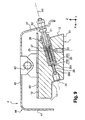
- outlet pipe 24 described with reference to Figures 1 to 8 was made in the form of a vertical bore opening into the lower face 10, but it could have been made in the continuity of the channel of distribution 210, along the longitudinal axis Y, instead of the end which opens into the peripheral face 12 and which is blocked by the screw 211, as is the case in the embodiment illustrated in FIGS. figures 9 and 10 .
- the external receiver is connected at the peripheral face 12 of the body 1.
Landscapes
- Engineering & Computer Science (AREA)
- Physics & Mathematics (AREA)
- Fluid Mechanics (AREA)
- Mechanical Engineering (AREA)
- General Engineering & Computer Science (AREA)
- Fluid-Damping Devices (AREA)
- Safety Valves (AREA)
- Mechanically-Actuated Valves (AREA)
- Multiple-Way Valves (AREA)
- Servomotors (AREA)
- Valve Housings (AREA)
Claims (12)
- Druckreglervorrichtung, insbesondere der hydraulischen Fernbetätigungsart, die umfasst:- einen Körper (1), der mit zwei Endseiten, jeweils einer Oberseite (10) und einer Unterseite (11), versehen ist, und einer peripheren Seite (12), die sich zwischen den zwei Endseiten (10, 11) erstreckt, und mindestens einen Betätigungshohlraum (20), der auf mindestens einer der Seiten mündet, und mindestens einen Dämpfungshohlraum (30), der auf mindestens einer der Seiten mündet, umfasst,- mindestens einen in den Körper (1) eingebauten Druckreduzierer (2), der einen Betätigungsschalter (21) umfasst, der in Hin- und Herbewegung in dem mindestens einen Betätigungshohlraum (20) untergebracht ist, wobei der Druckreduzierer (2) dazu bestimmt ist, die Betätigung mindestens eines Empfängers außerhalb der Reglervorrichtung zu erlauben,- ein Betätigungsorgan (4), das im Verhältnis zum Körper (1) mittels eines auf der Oberseite (10) des Körpers (1) montierten Gelenks (42) kippbar montiert ist, um die Hin- und Herbewegung des mindestens einen Betätigungsschalters (21) zu steuern, und- mindestens eine im Körper (1) montierte Dämpfungsvorrichtung (3), die zwei Dämpfungsschalter (31) umfasst, die auf der einen und der anderen Seite des Gelenks (42) angeordnet sind und in Hin- und Herbewegung in dem mindestens einen Dämpfungshohlraum (30) untergebracht sind, wobei die Dämpfungsvorrichtung (3) dazu bestimmt ist, das Kippen des Betätigungsorgans (4) in die eine Richtung und in die andere zu dämpfen, wobei das Betätigungsorgan (4) einerseits einen der Dämpfungsschalter (31) drückt, wenn es in eine Richtung kippt, und andererseits den anderen der Dämpfungsschalter (31), wenn es in die andere Richtung kippt,
wobei die Vorrichtung dadurch gekennzeichnet ist, dass der mindestens eine Betätigungshohlraum (20) ein in die periphere Seite (12) des Körpers (1) mündendes Ende aufweist und dass der mindestens eine Dämpfungshohlraum (30) zwei in die periphere Seite (12) des Körpers auf der einen und der anderen Seite des Gelenks (42) des Betätigungsorgans (4) mündende Enden aufweist und dass das Betätigungsorgan (4) Abschnitte (47) gegenüber der peripheren Seite (12) aufweist, um den mündenden Enden der Betätigungs- (20) beziehungsweise Dämpfungs-(30) Hohlräume gegenüberzustehen, aus denen die Betätigungs- (21) und Dämpfungs-(31)Schalter hervorstehen. - Vorrichtung nach Anspruch 1, die einen einzigen geraden Dämpfungshohlraum (30) umfasst, der den Körper (1) von der einen zur anderen Seite durchquert und an seinen zwei Enden an seiner peripheren Seite (12) mündet.
- Vorrichtung nach Anspruch 2, wobei der mindestens eine Betätigungshohlraum (20) gerade ist und sich im Verhältnis zum Dämpfungshohlraum (30) etwa parallel oder geneigt erstreckt.
- Vorrichtung nach den Ansprüchen 2 oder 3, wobei sich der Dämpfungshohlraum (30) und der mindestens eine Betätigungshohlraum (20) in etwa parallelen Ebenen erstrecken.
- Vorrichtung nach einem der vorangehenden Ansprüche, wobei die Dämpfungsvorrichtung (3) einen Dämpfungsschieber (32) umfasst, der gleitend und mit Anpassung im Dämpfungshohlraum (30) montiert ist, und wobei der Dämpfungshohlraum (30) zwei Arbeitskammern (300) mit variablem Volumen in entgegengesetzter Richtung, die sich zwischen den zwei gegenüberliegenden Enden des Dämpfungsschiebers (32) erstrecken, und auf Ebene der mündenden Enden des Dämpfungshohlraums (30) unbewegliche Führungsmuffen (38) umfasst, um die jeweiligen Dämpfungsschalter (31) verschiebend zu führen, wobei die Arbeitskammern (300) ein Fluid enthalten, das dazu bestimmt ist, durch mindesten einen Kommunikationsdurchgang unter der Wirkung des Schubs des einen oder des anderen der Dämpfungsschalter (31) über den Dämpfungsschieber (32) von der einen zur anderen zu fließen.
- Vorrichtung nach Anspruch 5, wobei der Kommunikationsdurchgang mindestens eine Verengungszone (342; 343) umfasst, die ausgebildet ist, um einen Lastverlust in dem Kommunikationsdurchgang zu erzeugen, wenn er von zwischen den zwei Arbeitskammern (300) fließendem Fluid durchquert wird.
- Vorrichtung nach den Ansprüchen 5 oder 6, wobei der Dämpfungsschieber (32) an seinen beiden jeweiligen Enden zwei jeweilige Endkolben (33) umfasst, die im Dämpfungshohlraum (30) gleiten, die miteinander durch eine zentrale Stange (34) verbunden sind, und gegen die die jeweiligen Dämpfungsschalter (31) im Anschlag sind, und wobei der Kommunikationsdurchgang zwischen den zwei Arbeitskammern (300) im Dämpfungsschieber (32) zwischen den zwei Endkolben (33) ausgebildet ist.
- Vorrichtung nach Anspruch 7, wobei der Kommunikationsdurchgang zwei Endkanäle (343) umfasst, die in den Endkolben (33) ausgebildet sind, und einen zentralen Kanal (340), der axial in der zentralen Verbindungsstange (34) zwischen den zwei Endkolben (33) ausgebildet ist, wobei die Endkanäle (343) die jeweiligen Arbeitskammern (300) und den zentralen Kanal (340) in Fluidkommunikation versetzen.
- Vorrichtung nach Anspruch 8, wobei der zentrale Kanal (340) die zwei Endkolben (33) von einer Seite zur anderen durchquert, wobei die Dämpfungsschalter (31) dimensioniert sind, um die jeweiligen mündenden Enden (341) des zentralen Kanals (340) zu verschließen, und wobei die Endkanäle (343) die Form von Rillen aufweisen, die auf den Seiten am Ende der jeweiligen Endkolben (33) eingearbeitet sind und die jeweiligen Arbeitskammern (300) und die jeweiligen mündenden Enden (341) des zentralen Kanals (340) in Fluidkommunikation versetzen.
- Vorrichtung nach Anspruch 9, wobei die Rillen (343) eine allgemeine Spiralform aufweisen, die geeignet ist, um eine Verengung beim Fließen des Fluids zwischen den jeweiligen Arbeitskammern (300) und dem zentralen Kanal (340) zu bilden.
- Vorrichtung nach einem der Ansprüche 8 bis 10, wobei der zentrale Kanal (340) innen mit zwei antagonistischen Düsen (342) ausgerüstet ist, die ausgebildet sind, um Lastverluste im Fluidfluss im zentralen Kanal (340) zu erzeugen.
- Vorrichtung nach einem der Ansprüche 7 bis 11, wobei der Verteilungsschieber (32) zwei Übergangskolben (35) umfasst, die im Dämpfungshohlraum (30) gleiten und um die zentrale Stange (34) zwischen den Endkolben (33) derart angeordnet sind, dass der Verteilungsschieber (32) innen drei innere Kammern mit konstantem Volumen begrenzt, nämlich zwei seitliche innere Kammern (321), die zwischen den Endkolben (33) und den benachbarten Übergangskolben (35) angeordnet sind, und eine zentrale innere Kammer, die zwischen den zwei Übergangskolben (35) angeordnet ist.
Applications Claiming Priority (2)
| Application Number | Priority Date | Filing Date | Title |
|---|---|---|---|
| FR0806293A FR2938309B1 (fr) | 2008-11-12 | 2008-11-12 | Dispositif de regulation de pression, notamment du type telecommande hydraulique |
| PCT/FR2009/051980 WO2010055240A1 (fr) | 2008-11-12 | 2009-10-16 | Dispositif de regulation de pression, notamment du type telecommande hydraulique |
Publications (2)
| Publication Number | Publication Date |
|---|---|
| EP2344773A1 EP2344773A1 (de) | 2011-07-20 |
| EP2344773B1 true EP2344773B1 (de) | 2013-03-13 |
Family
ID=40852528
Family Applications (1)
| Application Number | Title | Priority Date | Filing Date |
|---|---|---|---|
| EP20090760165 Not-in-force EP2344773B1 (de) | 2008-11-12 | 2009-10-16 | Druckreglervorrichtung, insbesondere der hydraulischen fernsteuerungsart |
Country Status (5)
| Country | Link |
|---|---|
| US (1) | US8434519B2 (de) |
| EP (1) | EP2344773B1 (de) |
| JP (1) | JP5373114B2 (de) |
| FR (1) | FR2938309B1 (de) |
| WO (1) | WO2010055240A1 (de) |
Family Cites Families (29)
| Publication number | Priority date | Publication date | Assignee | Title |
|---|---|---|---|---|
| FR1291415A (fr) * | 1960-07-12 | 1962-04-20 | Daimler Benz Ag | Commutateur hydraulique actionné mécaniquement, en particulier pour dispositifs deréglage sur des voitures automobiles |
| FR2080173A5 (de) * | 1970-02-25 | 1971-11-12 | Snecma | |
| US3935792A (en) * | 1973-02-26 | 1976-02-03 | Caterpillar Tractor Co. | Pilot pump bleed control for earthmoving scrapers |
| FR2376978A1 (fr) * | 1977-01-06 | 1978-08-04 | Rexroth Sigma | Perfectionnements aux dispositifs distributeurs de fluide, notamment pour telecommande hydraulique |
| FR2507732B1 (fr) * | 1981-06-12 | 1985-08-02 | Rexroth Sigma | Perfectionnements apportes aux plongeurs pour reducteurs de pression de fluide, reducteurs et distributeurs equipes de tels plongeurs |
| DE3678090D1 (de) * | 1985-09-06 | 1991-04-18 | Hitachi Construction Machinery | Hydraulisches vorsteuersystem fuer die bedienung von wegeventilen. |
| JPH0332869Y2 (de) * | 1986-12-22 | 1991-07-11 | ||
| JPH01226697A (ja) * | 1988-03-03 | 1989-09-11 | Kobe Steel Ltd | 建設機械における操作レバーの操作反力制御装置 |
| JPH07103942B2 (ja) * | 1988-03-31 | 1995-11-08 | 株式会社小松製作所 | 油圧パイロットバルブ装置 |
| DE68912508T2 (de) * | 1988-10-26 | 1994-05-19 | Kabushiki Kaisha Kobe Seiko Sho (Kobe Steel Ltd.), Kobe | Steuervorrichtung für die auf einen Steuerhebel auszuübende Kraft. |
| US5156065A (en) * | 1988-11-11 | 1992-10-20 | Kabushiki Kaisha Kobe Seiko Sho | Control lever apparatus and actuator operation apparatus |
| US5305782A (en) * | 1993-01-22 | 1994-04-26 | Diesel Equipment Limited | Pneumatic control valve system |
| JP3503756B2 (ja) * | 1993-09-28 | 2004-03-08 | 株式会社小松製作所 | 油圧パイロット弁のダンパ装置 |
| JP2786401B2 (ja) * | 1994-11-10 | 1998-08-13 | 川崎重工業株式会社 | 油圧操作弁 |
| US5638866A (en) * | 1996-03-01 | 1997-06-17 | Dana Corporation | Detent arrangement for holding hydraulic valve members stroked |
| JP3337121B2 (ja) * | 1997-05-22 | 2002-10-21 | 川崎重工業株式会社 | パイロット弁 |
| FR2793532B1 (fr) * | 1999-05-12 | 2001-08-03 | Mannesmann Rexroth Sa | Dispositif distributeur de fluide notamment pour telecommande hydraulique |
| DE19961052A1 (de) * | 1999-12-16 | 2001-07-26 | Sauer Danfoss Gmbh | Steuervorrichtung für die manuell- oder fußgeführte Steuerung von Arbeitsmaschinen |
| JP4562902B2 (ja) * | 2000-12-01 | 2010-10-13 | 株式会社小松製作所 | 減圧弁 |
| JP2003097513A (ja) * | 2001-09-25 | 2003-04-03 | Hitachi Constr Mach Co Ltd | 減圧弁型パイロット弁 |
| US6634383B2 (en) * | 2001-12-14 | 2003-10-21 | Caterpillar Inc. | Magnetic detent assist assembly |
| FR2835574B1 (fr) * | 2002-02-04 | 2004-10-29 | Mannesmann Rexroth Sa | Dispositif de regulation de pression pour une telecommande hydraulique |
| FR2854668B1 (fr) * | 2003-05-05 | 2006-07-07 | Rexroth Sa | Distributeur de fluide sous pression a guide double |
| FR2857489B1 (fr) * | 2003-07-11 | 2006-06-09 | Bosch Rexroth Dsi Sas | Telecommande pour engins de travaux publics a poussoir suiveur |
| FR2857706B1 (fr) * | 2003-07-17 | 2007-05-04 | Bosch Rexroth Dsi Sas | Dispositif distributeur de fluide sous pression a double ressorts de regulation |
| WO2005033823A1 (ja) * | 2003-09-30 | 2005-04-14 | Komatsu Ltd. | 操作レバー装置 |
| JP4572526B2 (ja) * | 2003-10-24 | 2010-11-04 | 日産自動車株式会社 | 車輪独立懸架装置 |
| ITPR20050062A1 (it) * | 2005-10-20 | 2006-01-19 | Walvoil Spa | Servocomando idraulico con sistema di smorzamento delle oscillazioni. |
| DE102006042629A1 (de) * | 2006-09-05 | 2008-03-20 | ITT Mfg. Enterprises, Inc., Wilmington | Schaltknüppel |
-
2008
- 2008-11-12 FR FR0806293A patent/FR2938309B1/fr not_active Expired - Fee Related
-
2009
- 2009-10-16 JP JP2011543792A patent/JP5373114B2/ja not_active Expired - Fee Related
- 2009-10-16 EP EP20090760165 patent/EP2344773B1/de not_active Not-in-force
- 2009-10-16 US US13/129,039 patent/US8434519B2/en not_active Expired - Fee Related
- 2009-10-16 WO PCT/FR2009/051980 patent/WO2010055240A1/fr not_active Ceased
Also Published As
| Publication number | Publication date |
|---|---|
| US8434519B2 (en) | 2013-05-07 |
| US20110214751A1 (en) | 2011-09-08 |
| JP5373114B2 (ja) | 2013-12-18 |
| EP2344773A1 (de) | 2011-07-20 |
| JP2012508360A (ja) | 2012-04-05 |
| FR2938309B1 (fr) | 2010-10-29 |
| WO2010055240A1 (fr) | 2010-05-20 |
| FR2938309A1 (fr) | 2010-05-14 |
Similar Documents
| Publication | Publication Date | Title |
|---|---|---|
| EP0117806B1 (de) | Flüssigkeitsverteiler, insbesondere für Fernsteuerung | |
| FR2690494A1 (fr) | Systeme de valve de regulation de pression d'huile pour transmissions hydrostatiques | |
| FR2767932A1 (fr) | Dispositif de regulation de debit volumique et systeme d'injection comportant un tel dispositif de regulation, notamment pour moteur a combustion interne | |
| EP3163076B1 (de) | Hydraulische maschine mit zwei schluckvolumina und einem sicherheitsventil | |
| EP2344773A1 (de) | Druckreglervorrichtung, insbesondere der hydraulischen fernsteuerungsart | |
| FR2468771A1 (fr) | Dispositif de commande d'aspiration pour un compresseur | |
| FR2534345A1 (fr) | Commande de debit pour interface par clapet | |
| EP1501694A1 (de) | Einziehbares ablagesystem für kabriolett mit faltdach | |
| FR2894303A1 (fr) | Verin hydraulique a amortissement | |
| FR3099430A1 (fr) | Dispositif d’appui-tête et siège de véhicule comportant un tel appui-tête | |
| FR2765924A1 (fr) | Dispositif permettant de commander deux verins | |
| EP0615500B1 (de) | Hydraulische lenkvorrichtung mit beweglichem ventil | |
| WO1985002446A1 (fr) | Perfectionnement aux limites de debit d'air comprime | |
| FR2565637A1 (fr) | Convertisseur de pression a double effet | |
| EP0045268B1 (de) | Drosselvorrichtung | |
| EP0185565B1 (de) | Niveauregelventil zum Konstanthalten der Lage eines ersten Teils hinsichtlich eines zweiten Teils und Anwendung dazu zur Luftfederung | |
| EP1646791B1 (de) | Reversible steuervorrichtung zur verteilung von hochdruckfluid | |
| FR2835574A1 (fr) | Dispositif de regulation de pression pour une telecommande hydraulique | |
| FR2814510A1 (fr) | Distributeur hydraulique, circuit hydraulique comprenant un tel distributeur pour la commande des mouvements de deux verins double effet | |
| EP1111248B1 (de) | Stellglied mit zwischenliegender Haltestellung | |
| FR2508566A1 (fr) | Distributeur de commande de verin | |
| FR2590759A1 (fr) | Perfectionnements aux charrues reversibles | |
| FR3070003B1 (fr) | Dispositif de regulation hydraulique pour systeme de commande avec amortissement pour rampe de pulverisation, et systeme comprenant ledit dispositif | |
| EP0438936A1 (de) | Einrichtung zum automatischen Rückstellen eines hydraulischen Differentialzylinders | |
| FR2612573A1 (fr) | Cylindre a milieu sous pression et a double action |
Legal Events
| Date | Code | Title | Description |
|---|---|---|---|
| PUAI | Public reference made under article 153(3) epc to a published international application that has entered the european phase |
Free format text: ORIGINAL CODE: 0009012 |
|
| 17P | Request for examination filed |
Effective date: 20110324 |
|
| AK | Designated contracting states |
Kind code of ref document: A1 Designated state(s): AT BE BG CH CY CZ DE DK EE ES FI FR GB GR HR HU IE IS IT LI LT LU LV MC MK MT NL NO PL PT RO SE SI SK SM TR |
|
| AX | Request for extension of the european patent |
Extension state: AL BA RS |
|
| DAX | Request for extension of the european patent (deleted) | ||
| GRAP | Despatch of communication of intention to grant a patent |
Free format text: ORIGINAL CODE: EPIDOSNIGR1 |
|
| GRAS | Grant fee paid |
Free format text: ORIGINAL CODE: EPIDOSNIGR3 |
|
| GRAA | (expected) grant |
Free format text: ORIGINAL CODE: 0009210 |
|
| AK | Designated contracting states |
Kind code of ref document: B1 Designated state(s): AT BE BG CH CY CZ DE DK EE ES FI FR GB GR HR HU IE IS IT LI LT LU LV MC MK MT NL NO PL PT RO SE SI SK SM TR |
|
| REG | Reference to a national code |
Ref country code: GB Ref legal event code: FG4D Free format text: NOT ENGLISH |
|
| REG | Reference to a national code |
Ref country code: CH Ref legal event code: EP Ref country code: AT Ref legal event code: REF Ref document number: 600966 Country of ref document: AT Kind code of ref document: T Effective date: 20130315 |
|
| REG | Reference to a national code |
Ref country code: IE Ref legal event code: FG4D Free format text: LANGUAGE OF EP DOCUMENT: FRENCH |
|
| REG | Reference to a national code |
Ref country code: DE Ref legal event code: R096 Ref document number: 602009013933 Country of ref document: DE Effective date: 20130508 |
|
| PG25 | Lapsed in a contracting state [announced via postgrant information from national office to epo] |
Ref country code: NO Free format text: LAPSE BECAUSE OF FAILURE TO SUBMIT A TRANSLATION OF THE DESCRIPTION OR TO PAY THE FEE WITHIN THE PRESCRIBED TIME-LIMIT Effective date: 20130613 Ref country code: BG Free format text: LAPSE BECAUSE OF FAILURE TO SUBMIT A TRANSLATION OF THE DESCRIPTION OR TO PAY THE FEE WITHIN THE PRESCRIBED TIME-LIMIT Effective date: 20130613 Ref country code: SE Free format text: LAPSE BECAUSE OF FAILURE TO SUBMIT A TRANSLATION OF THE DESCRIPTION OR TO PAY THE FEE WITHIN THE PRESCRIBED TIME-LIMIT Effective date: 20130313 Ref country code: LT Free format text: LAPSE BECAUSE OF FAILURE TO SUBMIT A TRANSLATION OF THE DESCRIPTION OR TO PAY THE FEE WITHIN THE PRESCRIBED TIME-LIMIT Effective date: 20130313 Ref country code: ES Free format text: LAPSE BECAUSE OF FAILURE TO SUBMIT A TRANSLATION OF THE DESCRIPTION OR TO PAY THE FEE WITHIN THE PRESCRIBED TIME-LIMIT Effective date: 20130624 |
|
| REG | Reference to a national code |
Ref country code: AT Ref legal event code: MK05 Ref document number: 600966 Country of ref document: AT Kind code of ref document: T Effective date: 20130313 |
|
| REG | Reference to a national code |
Ref country code: NL Ref legal event code: VDEP Effective date: 20130313 |
|
| REG | Reference to a national code |
Ref country code: LT Ref legal event code: MG4D |
|
| PG25 | Lapsed in a contracting state [announced via postgrant information from national office to epo] |
Ref country code: SI Free format text: LAPSE BECAUSE OF FAILURE TO SUBMIT A TRANSLATION OF THE DESCRIPTION OR TO PAY THE FEE WITHIN THE PRESCRIBED TIME-LIMIT Effective date: 20130313 Ref country code: GR Free format text: LAPSE BECAUSE OF FAILURE TO SUBMIT A TRANSLATION OF THE DESCRIPTION OR TO PAY THE FEE WITHIN THE PRESCRIBED TIME-LIMIT Effective date: 20130614 Ref country code: LV Free format text: LAPSE BECAUSE OF FAILURE TO SUBMIT A TRANSLATION OF THE DESCRIPTION OR TO PAY THE FEE WITHIN THE PRESCRIBED TIME-LIMIT Effective date: 20130313 Ref country code: FI Free format text: LAPSE BECAUSE OF FAILURE TO SUBMIT A TRANSLATION OF THE DESCRIPTION OR TO PAY THE FEE WITHIN THE PRESCRIBED TIME-LIMIT Effective date: 20130313 |
|
| PG25 | Lapsed in a contracting state [announced via postgrant information from national office to epo] |
Ref country code: HR Free format text: LAPSE BECAUSE OF FAILURE TO SUBMIT A TRANSLATION OF THE DESCRIPTION OR TO PAY THE FEE WITHIN THE PRESCRIBED TIME-LIMIT Effective date: 20130313 |
|
| PG25 | Lapsed in a contracting state [announced via postgrant information from national office to epo] |
Ref country code: PT Free format text: LAPSE BECAUSE OF FAILURE TO SUBMIT A TRANSLATION OF THE DESCRIPTION OR TO PAY THE FEE WITHIN THE PRESCRIBED TIME-LIMIT Effective date: 20130715 Ref country code: NL Free format text: LAPSE BECAUSE OF FAILURE TO SUBMIT A TRANSLATION OF THE DESCRIPTION OR TO PAY THE FEE WITHIN THE PRESCRIBED TIME-LIMIT Effective date: 20130313 Ref country code: RO Free format text: LAPSE BECAUSE OF FAILURE TO SUBMIT A TRANSLATION OF THE DESCRIPTION OR TO PAY THE FEE WITHIN THE PRESCRIBED TIME-LIMIT Effective date: 20130313 Ref country code: SK Free format text: LAPSE BECAUSE OF FAILURE TO SUBMIT A TRANSLATION OF THE DESCRIPTION OR TO PAY THE FEE WITHIN THE PRESCRIBED TIME-LIMIT Effective date: 20130313 Ref country code: EE Free format text: LAPSE BECAUSE OF FAILURE TO SUBMIT A TRANSLATION OF THE DESCRIPTION OR TO PAY THE FEE WITHIN THE PRESCRIBED TIME-LIMIT Effective date: 20130313 Ref country code: CZ Free format text: LAPSE BECAUSE OF FAILURE TO SUBMIT A TRANSLATION OF THE DESCRIPTION OR TO PAY THE FEE WITHIN THE PRESCRIBED TIME-LIMIT Effective date: 20130313 Ref country code: AT Free format text: LAPSE BECAUSE OF FAILURE TO SUBMIT A TRANSLATION OF THE DESCRIPTION OR TO PAY THE FEE WITHIN THE PRESCRIBED TIME-LIMIT Effective date: 20130313 Ref country code: IS Free format text: LAPSE BECAUSE OF FAILURE TO SUBMIT A TRANSLATION OF THE DESCRIPTION OR TO PAY THE FEE WITHIN THE PRESCRIBED TIME-LIMIT Effective date: 20130713 |
|
| PG25 | Lapsed in a contracting state [announced via postgrant information from national office to epo] |
Ref country code: PL Free format text: LAPSE BECAUSE OF FAILURE TO SUBMIT A TRANSLATION OF THE DESCRIPTION OR TO PAY THE FEE WITHIN THE PRESCRIBED TIME-LIMIT Effective date: 20130313 Ref country code: CY Free format text: LAPSE BECAUSE OF FAILURE TO SUBMIT A TRANSLATION OF THE DESCRIPTION OR TO PAY THE FEE WITHIN THE PRESCRIBED TIME-LIMIT Effective date: 20130313 |
|
| PLBE | No opposition filed within time limit |
Free format text: ORIGINAL CODE: 0009261 |
|
| STAA | Information on the status of an ep patent application or granted ep patent |
Free format text: STATUS: NO OPPOSITION FILED WITHIN TIME LIMIT |
|
| PG25 | Lapsed in a contracting state [announced via postgrant information from national office to epo] |
Ref country code: DK Free format text: LAPSE BECAUSE OF FAILURE TO SUBMIT A TRANSLATION OF THE DESCRIPTION OR TO PAY THE FEE WITHIN THE PRESCRIBED TIME-LIMIT Effective date: 20130313 |
|
| 26N | No opposition filed |
Effective date: 20131216 |
|
| PG25 | Lapsed in a contracting state [announced via postgrant information from national office to epo] |
Ref country code: IT Free format text: LAPSE BECAUSE OF FAILURE TO SUBMIT A TRANSLATION OF THE DESCRIPTION OR TO PAY THE FEE WITHIN THE PRESCRIBED TIME-LIMIT Effective date: 20130313 |
|
| REG | Reference to a national code |
Ref country code: DE Ref legal event code: R097 Ref document number: 602009013933 Country of ref document: DE Effective date: 20131216 |
|
| BERE | Be: lapsed |
Owner name: BOSCH REXROTH D.S.I. Effective date: 20131031 |
|
| PG25 | Lapsed in a contracting state [announced via postgrant information from national office to epo] |
Ref country code: MC Free format text: LAPSE BECAUSE OF FAILURE TO SUBMIT A TRANSLATION OF THE DESCRIPTION OR TO PAY THE FEE WITHIN THE PRESCRIBED TIME-LIMIT Effective date: 20130313 |
|
| REG | Reference to a national code |
Ref country code: CH Ref legal event code: PL |
|
| GBPC | Gb: european patent ceased through non-payment of renewal fee |
Effective date: 20131016 |
|
| REG | Reference to a national code |
Ref country code: IE Ref legal event code: MM4A |
|
| PG25 | Lapsed in a contracting state [announced via postgrant information from national office to epo] |
Ref country code: CH Free format text: LAPSE BECAUSE OF NON-PAYMENT OF DUE FEES Effective date: 20131031 Ref country code: LI Free format text: LAPSE BECAUSE OF NON-PAYMENT OF DUE FEES Effective date: 20131031 Ref country code: GB Free format text: LAPSE BECAUSE OF NON-PAYMENT OF DUE FEES Effective date: 20131016 |
|
| REG | Reference to a national code |
Ref country code: DE Ref legal event code: R119 Ref document number: 602009013933 Country of ref document: DE Effective date: 20140501 |
|
| PG25 | Lapsed in a contracting state [announced via postgrant information from national office to epo] |
Ref country code: DE Free format text: LAPSE BECAUSE OF NON-PAYMENT OF DUE FEES Effective date: 20140501 |
|
| PG25 | Lapsed in a contracting state [announced via postgrant information from national office to epo] |
Ref country code: BE Free format text: LAPSE BECAUSE OF NON-PAYMENT OF DUE FEES Effective date: 20131031 |
|
| PG25 | Lapsed in a contracting state [announced via postgrant information from national office to epo] |
Ref country code: IE Free format text: LAPSE BECAUSE OF NON-PAYMENT OF DUE FEES Effective date: 20131016 |
|
| PG25 | Lapsed in a contracting state [announced via postgrant information from national office to epo] |
Ref country code: SM Free format text: LAPSE BECAUSE OF FAILURE TO SUBMIT A TRANSLATION OF THE DESCRIPTION OR TO PAY THE FEE WITHIN THE PRESCRIBED TIME-LIMIT Effective date: 20130313 |
|
| PG25 | Lapsed in a contracting state [announced via postgrant information from national office to epo] |
Ref country code: TR Free format text: LAPSE BECAUSE OF FAILURE TO SUBMIT A TRANSLATION OF THE DESCRIPTION OR TO PAY THE FEE WITHIN THE PRESCRIBED TIME-LIMIT Effective date: 20130313 |
|
| PG25 | Lapsed in a contracting state [announced via postgrant information from national office to epo] |
Ref country code: HU Free format text: LAPSE BECAUSE OF FAILURE TO SUBMIT A TRANSLATION OF THE DESCRIPTION OR TO PAY THE FEE WITHIN THE PRESCRIBED TIME-LIMIT; INVALID AB INITIO Effective date: 20091016 Ref country code: MK Free format text: LAPSE BECAUSE OF FAILURE TO SUBMIT A TRANSLATION OF THE DESCRIPTION OR TO PAY THE FEE WITHIN THE PRESCRIBED TIME-LIMIT Effective date: 20130313 Ref country code: LU Free format text: LAPSE BECAUSE OF NON-PAYMENT OF DUE FEES Effective date: 20131016 |
|
| PG25 | Lapsed in a contracting state [announced via postgrant information from national office to epo] |
Ref country code: MT Free format text: LAPSE BECAUSE OF FAILURE TO SUBMIT A TRANSLATION OF THE DESCRIPTION OR TO PAY THE FEE WITHIN THE PRESCRIBED TIME-LIMIT Effective date: 20130313 |
|
| REG | Reference to a national code |
Ref country code: FR Ref legal event code: PLFP Year of fee payment: 7 |
|
| PGFP | Annual fee paid to national office [announced via postgrant information from national office to epo] |
Ref country code: FR Payment date: 20150831 Year of fee payment: 7 |
|
| REG | Reference to a national code |
Ref country code: FR Ref legal event code: ST Effective date: 20170630 |
|
| PG25 | Lapsed in a contracting state [announced via postgrant information from national office to epo] |
Ref country code: FR Free format text: LAPSE BECAUSE OF NON-PAYMENT OF DUE FEES Effective date: 20161102 |