EP2344932B1 - Procédé de fabrication d'un réseau de diffraction multi-axes amélioré - Google Patents
Procédé de fabrication d'un réseau de diffraction multi-axes amélioré Download PDFInfo
- Publication number
- EP2344932B1 EP2344932B1 EP09825563.1A EP09825563A EP2344932B1 EP 2344932 B1 EP2344932 B1 EP 2344932B1 EP 09825563 A EP09825563 A EP 09825563A EP 2344932 B1 EP2344932 B1 EP 2344932B1
- Authority
- EP
- European Patent Office
- Prior art keywords
- beams
- light
- photodefinable
- embossing
- diffraction grating
- Prior art date
- Legal status (The legal status is an assumption and is not a legal conclusion. Google has not performed a legal analysis and makes no representation as to the accuracy of the status listed.)
- Not-in-force
Links
- 238000004519 manufacturing process Methods 0.000 title claims description 5
- 238000004049 embossing Methods 0.000 claims description 37
- 238000000034 method Methods 0.000 claims description 25
- 230000003287 optical effect Effects 0.000 claims description 17
- 229920002120 photoresistant polymer Polymers 0.000 claims description 13
- 230000001427 coherent effect Effects 0.000 claims description 10
- 239000000839 emulsion Substances 0.000 claims description 5
- 239000002184 metal Substances 0.000 claims description 4
- 229910052751 metal Inorganic materials 0.000 claims description 4
- 238000013507 mapping Methods 0.000 claims 1
- 239000000758 substrate Substances 0.000 description 14
- 239000002985 plastic film Substances 0.000 description 6
- 229920006255 plastic film Polymers 0.000 description 6
- 230000008901 benefit Effects 0.000 description 5
- 239000000463 material Substances 0.000 description 4
- 239000000123 paper Substances 0.000 description 4
- 239000003086 colorant Substances 0.000 description 3
- 230000000694 effects Effects 0.000 description 3
- 239000011888 foil Substances 0.000 description 3
- 230000000007 visual effect Effects 0.000 description 3
- PXHVJJICTQNCMI-UHFFFAOYSA-N Nickel Chemical compound [Ni] PXHVJJICTQNCMI-UHFFFAOYSA-N 0.000 description 2
- 239000011521 glass Substances 0.000 description 2
- 239000004033 plastic Substances 0.000 description 2
- 230000015572 biosynthetic process Effects 0.000 description 1
- 239000011111 cardboard Substances 0.000 description 1
- 238000000576 coating method Methods 0.000 description 1
- 238000011109 contamination Methods 0.000 description 1
- 230000003292 diminished effect Effects 0.000 description 1
- 238000005530 etching Methods 0.000 description 1
- 238000005286 illumination Methods 0.000 description 1
- 230000002452 interceptive effect Effects 0.000 description 1
- 150000002739 metals Chemical class 0.000 description 1
- 238000012986 modification Methods 0.000 description 1
- 230000004048 modification Effects 0.000 description 1
- 229910052759 nickel Inorganic materials 0.000 description 1
- 229920001721 polyimide Polymers 0.000 description 1
- 229910052709 silver Inorganic materials 0.000 description 1
- 239000004332 silver Substances 0.000 description 1
- 238000001228 spectrum Methods 0.000 description 1
- 239000000126 substance Substances 0.000 description 1
Images




Classifications
-
- G—PHYSICS
- G02—OPTICS
- G02B—OPTICAL ELEMENTS, SYSTEMS OR APPARATUS
- G02B5/00—Optical elements other than lenses
- G02B5/18—Diffraction gratings
- G02B5/1847—Manufacturing methods
- G02B5/1857—Manufacturing methods using exposure or etching means, e.g. holography, photolithography, exposure to electron or ion beams
-
- G—PHYSICS
- G03—PHOTOGRAPHY; CINEMATOGRAPHY; ANALOGOUS TECHNIQUES USING WAVES OTHER THAN OPTICAL WAVES; ELECTROGRAPHY; HOLOGRAPHY
- G03H—HOLOGRAPHIC PROCESSES OR APPARATUS
- G03H1/00—Holographic processes or apparatus using light, infrared or ultraviolet waves for obtaining holograms or for obtaining an image from them; Details peculiar thereto
- G03H1/02—Details of features involved during the holographic process; Replication of holograms without interference recording
- G03H1/0276—Replicating a master hologram without interference recording
- G03H1/028—Replicating a master hologram without interference recording by embossing
-
- G—PHYSICS
- G03—PHOTOGRAPHY; CINEMATOGRAPHY; ANALOGOUS TECHNIQUES USING WAVES OTHER THAN OPTICAL WAVES; ELECTROGRAPHY; HOLOGRAPHY
- G03H—HOLOGRAPHIC PROCESSES OR APPARATUS
- G03H1/00—Holographic processes or apparatus using light, infrared or ultraviolet waves for obtaining holograms or for obtaining an image from them; Details peculiar thereto
- G03H1/04—Processes or apparatus for producing holograms
-
- G—PHYSICS
- G03—PHOTOGRAPHY; CINEMATOGRAPHY; ANALOGOUS TECHNIQUES USING WAVES OTHER THAN OPTICAL WAVES; ELECTROGRAPHY; HOLOGRAPHY
- G03H—HOLOGRAPHIC PROCESSES OR APPARATUS
- G03H1/00—Holographic processes or apparatus using light, infrared or ultraviolet waves for obtaining holograms or for obtaining an image from them; Details peculiar thereto
- G03H1/02—Details of features involved during the holographic process; Replication of holograms without interference recording
- G03H1/024—Hologram nature or properties
- G03H1/0244—Surface relief holograms
-
- G—PHYSICS
- G03—PHOTOGRAPHY; CINEMATOGRAPHY; ANALOGOUS TECHNIQUES USING WAVES OTHER THAN OPTICAL WAVES; ELECTROGRAPHY; HOLOGRAPHY
- G03H—HOLOGRAPHIC PROCESSES OR APPARATUS
- G03H1/00—Holographic processes or apparatus using light, infrared or ultraviolet waves for obtaining holograms or for obtaining an image from them; Details peculiar thereto
- G03H1/26—Processes or apparatus specially adapted to produce multiple sub- holograms or to obtain images from them, e.g. multicolour technique
- G03H1/2645—Multiplexing processes, e.g. aperture, shift, or wavefront multiplexing
- G03H1/265—Angle multiplexing; Multichannel holograms
-
- G—PHYSICS
- G03—PHOTOGRAPHY; CINEMATOGRAPHY; ANALOGOUS TECHNIQUES USING WAVES OTHER THAN OPTICAL WAVES; ELECTROGRAPHY; HOLOGRAPHY
- G03H—HOLOGRAPHIC PROCESSES OR APPARATUS
- G03H1/00—Holographic processes or apparatus using light, infrared or ultraviolet waves for obtaining holograms or for obtaining an image from them; Details peculiar thereto
- G03H1/02—Details of features involved during the holographic process; Replication of holograms without interference recording
- G03H1/0276—Replicating a master hologram without interference recording
- G03H2001/0296—Formation of the master hologram
-
- G—PHYSICS
- G03—PHOTOGRAPHY; CINEMATOGRAPHY; ANALOGOUS TECHNIQUES USING WAVES OTHER THAN OPTICAL WAVES; ELECTROGRAPHY; HOLOGRAPHY
- G03H—HOLOGRAPHIC PROCESSES OR APPARATUS
- G03H1/00—Holographic processes or apparatus using light, infrared or ultraviolet waves for obtaining holograms or for obtaining an image from them; Details peculiar thereto
- G03H1/04—Processes or apparatus for producing holograms
- G03H1/0476—Holographic printer
- G03H2001/0482—Interference based printer
-
- G—PHYSICS
- G03—PHOTOGRAPHY; CINEMATOGRAPHY; ANALOGOUS TECHNIQUES USING WAVES OTHER THAN OPTICAL WAVES; ELECTROGRAPHY; HOLOGRAPHY
- G03H—HOLOGRAPHIC PROCESSES OR APPARATUS
- G03H1/00—Holographic processes or apparatus using light, infrared or ultraviolet waves for obtaining holograms or for obtaining an image from them; Details peculiar thereto
- G03H1/04—Processes or apparatus for producing holograms
- G03H1/0493—Special holograms not otherwise provided for, e.g. conoscopic, referenceless holography
- G03H2001/0497—Dot matrix holograms
-
- G—PHYSICS
- G03—PHOTOGRAPHY; CINEMATOGRAPHY; ANALOGOUS TECHNIQUES USING WAVES OTHER THAN OPTICAL WAVES; ELECTROGRAPHY; HOLOGRAPHY
- G03H—HOLOGRAPHIC PROCESSES OR APPARATUS
- G03H1/00—Holographic processes or apparatus using light, infrared or ultraviolet waves for obtaining holograms or for obtaining an image from them; Details peculiar thereto
- G03H1/22—Processes or apparatus for obtaining an optical image from holograms
- G03H1/2202—Reconstruction geometries or arrangements
- G03H2001/2236—Details of the viewing window
- G03H2001/2239—Enlarging the viewing window
-
- G—PHYSICS
- G03—PHOTOGRAPHY; CINEMATOGRAPHY; ANALOGOUS TECHNIQUES USING WAVES OTHER THAN OPTICAL WAVES; ELECTROGRAPHY; HOLOGRAPHY
- G03H—HOLOGRAPHIC PROCESSES OR APPARATUS
- G03H2260/00—Recording materials or recording processes
- G03H2260/50—Reactivity or recording processes
- G03H2260/62—Direct etching
Definitions
- the present invention is directed to a method of producing embossing shims. More particularly, the present invention pertains to a method of making embossing shims for the production of diffractive surfaces such as holograms or gratings having enhanced color shifting or optically variable backgrounds.
- Reflective transparent, semitransparent, and opaque materials containing embossed holographic images are commonly used in security and decorative applications such as passports, credit cards, security passes, licences, stamps, as well as gift wrap, book illustrations, and the like. Protection is achieved by affixing holographic or optically variable films to the documents. It is very difficult to forge and counterfeit such documents as such holographic or optically variable films are not easily copied using conventional printing techniques.
- Holographic films are generally produced by metalizing an embossed pattern of a three dimensional image.
- Traditional embossing applies pressure to either side of a material to alter the surface, giving the material a three dimensional or raised effect.
- traditional embossing transfers the 3D microstructure image to the material.
- Typical film embossing machines use two cylindrical rollers, an embossing roller, as shown in FIG. 1 .
- Film generally between 0.0010 cm and 0.0025 cm (.0004 and .001 inches) thick or greater, is pushed or pulled between the two rollers.
- the raised or textured embossing shim located on the embossing roller forces the film against the backing roller to create the embossed impression in the film.
- the film can later be laminated to paper, cardboard, plastic, metals, or other substrates.
- the embossed side of the impression may be aluminized or metalized to turn the 3D microstructure into a reflection hologram.
- Holographic patterns for the embossing shims are typically created by exposing a photosensitive emulsion-covered substrate to two beams from a coherent light source and etching or developing the resulting interference pattern into the photosensitive emulsion or photoresist.
- Holographic patterns typically include optical interference patterns such as diffraction gratings.
- a diffraction grating is an optical interference pattern in which a component with a regular pattern splits (diffracts) light into several beams traveling in different directions.
- Single axis diffraction gratings, producing large format rainbow reflective foil/film holograms, as shown in FIG. 2 are created by interfering two expanded beams of coherent light from a single laser. Incident light is diffracted in two directions.
- Diffraction gratings which produce an iridescent-type effect by diffracting ambient light into its color components, "rainbow holograms", are well-known in the art.
- Holographic images generally require direct illumination for the diffraction colors to be visible.
- the holographic image in order to view the diffraction colors, the holographic image must be viewed from the same angle from which the holographic image is illuminated.
- rainbow or iridescent colored light reflecting from the hologram is generally visible in only two directions, usually at 0 degrees and 180 degrees. When viewed from other directions or angles, color is not visible and the hologram appears dark or gray/silver. Thus, the field of view is relatively limited.
- a cross-grating pattern is a commonly produced optical interference pattern in which a single axis grating is used to create large format rainbow reflective foil/film holograms as described above, then the two beams are rotated with respect to the original grating by 90 degrees. Rotating the beams increases the field of view for the hologram, such that the field of view or rainbow color is visible from more than two angles.
- the resultant cross-grating diffracts light (i.e. allows color to be visible) in numerous (4 or more) directions based on the grating frequency, increasing the field of view.
- the light diffracts symmetrically at 0, 90, 180, and 270 degrees. Diffracted beams also appear symmetrically at the off angles (diagonals) (45, 135, 225, 315) at certain frequencies.
- an optical interference pattern such as a diffraction grating hologram
- U.S. Pat. No. 2007/037065 describes a method for ablating holographic patterns directly onto a surface of polymeric coatings deposited on an embossing cylinder using the interference of laser beams.
- US2002/0163680 A1 discloses a method of making an optical interference pattern on a photopolymer film by using a set of three expanded light beams directed onto said photopolymer film.
- the present invention provides a method according to claim 1.
- Embodiments of the method is according to claim 2.
- An enhanced optical interference pattern for an embossing shim such as an enhanced diffraction grating hologram, is created using three or more beams from a coherent source to produce a diffraction grating hologram which has a more intense or stronger visual effect that previous holograms when exposed to white light.
- Three or more beams of coherent light from a single source are directed toward a photodefinable surface, such as a photoresist plate or an ablatable substrate.
- the three beams interfere with one another and produce, on a given substrate, a diffraction grating hologram with in increased field of view than previous methods provided, without having to expose the substrate twice to the beams and without increased handling of the photoresist plate or ablatable substrate.
- an optical interference pattern such as a diffraction grating pattern
- a photodefineable surface such as a photosensitive emulsion/photoresist covered glass (“photoresist plate”) by exposing the photodefinable surface to three or more beams from a coherent light source.
- a photodefinable surface is directly ablated with three or more beams from a coherent light source.
- the photodefinable surface is electroplated to form a metal master shim.
- the photodefinable metal master is nickel-plated for use as an embossing shim. Formation of the optical interference pattern is created by interference of three or more light beams, such as laser light, arc light or other monochromatic light sources producing a suitable spectrum of light when illuminated by a point source such as sunlight, incandescent or florescent light.
- the resulting diffraction grating pattern is etched, developed or ablated onto the photodefinable surface.
- the etched/developed photodefinable surface is used to create embossing shims.
- the embossing shim can then be used to emboss film or paper in mass.
- the embossed film/paper can be metalized and laminated onto a substrate to create a holographic product that has shifting patterns and rainbow colors at a variety of viewing angles when exposed to white light.
- An enhanced optical interference pattern such as a diffraction grating foil/film hologram is created by directing or shining three or more beams of coherent light from a single source onto a photodefinable surface, such as a photoresist plate or an ablatable substrate.
- the three beams interfere with one another and produce an optical interference pattern on the photodefinable surface that provides more control of the angular playback resulting in a hologram having a wider field of view than previous methods provided, without having to expose the photodefinable surface twice to the beams and without increased handling of the photoresist plate.
- FIG. 1 there is shown an apparatus 10 for making shallow relief/holographic embossings on film or paper.
- An embossing cylinder or roller 12 and a backing cylinder or roller 14 are positioned adjacent one another with a nip 16 formed between the two rollers 12, 14.
- a film 18 is pushed or pulled through the nip 16, between the rollers 12, 14.
- An embossing shim 20 is wrapped around the embossing roller 12.
- an embossed image 22 is formed on the film 18.
- the embossing shims 20 used on the apparatus 10 described above having an enhanced diffraction grating pattern which is formed using an embodiment of the method described below.
- An optical interference pattern such as a diffraction grating, is produced by interference of light beams from a coherent source.
- Chart 1 illustrates an example of a sinusoidal wave pattern for light wave interference of two waves or two light beams.
- the first sinusoidal wave represents a light beam 32.
- the second sinusoidal wave represents a light beam 34, ninety degrees phase shifted from light wave 32.
- the third sinusoidal wave 33 represents the interference pattern of the two light beams 32, 34. As is shown, the two expanded light beams 32, 34 constructively interfere at intersection A and B to create a greater intensity light wave 33.
- the diffraction grating pattern 30 can have diffraction at a specific angle to the normal at 45 ( ⁇ /4), 135 (3 ⁇ /4), 225 (5 ⁇ /4), and 315 (7 ⁇ /4) degrees (with respect to wavelength interference), in addition to a similar set of diffractive angles with respect to the first set at 0,90 ( ⁇ /2), 180 ( ⁇ ), and 270 (3 ⁇ /2) degrees.
- Chart 2 illustrates an example of a sinusoidal wave pattern for light wave interference of three waves or three light beams from a coherent source.
- the first sinusoidal wave represents a beam 32.
- the second sinusoidal wave represents beam 34, ninety degrees phase shifted from light wave 32, and the third sinusoidal wave represents beam 36, phase shifted from the first two beams.
- the sinusoidal wave 33 illustrates the interference pattern of the two beams 32, 34, and sinusoidal wave 35 illustrates the interference pattern of light beams 34, 36.
- the two light beams 32, 34 add where they intersect at A and B to create a greater intensity light wave 33.
- Light beams 34 and 36 also form interference pattern wave 35 to create greater intensity of light when the two beams intersect at C and D.
- the diffraction grating pattern 30 can have diffraction at a specific angle to the normal at 45 ( ⁇ /4), 135 (3 ⁇ /4), 225 (5 ⁇ /4), and 315 (7 ⁇ /4) degrees (with respect to wavelength interference), in addition to a different set of diffractive angles with respect to the first set at 0,90 ( ⁇ /2), 180 ( ⁇ ), and 270 (3 ⁇ /2) degrees. In other words there can be multiple angles of diffraction for a wider viewing zone, or increased field of view, all achieved with one 3 beam exposure.
- Embodiments of the present invention are described as examples of the present method and are not intended to limit the present method to the embodiments described.
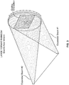
- An example of a diffraction grating pattern using an embodiment of the three beam method is shown in FIG. 4 .
- the optical interference pattern such as the diffraction pattern shown, arises when the three beams interfere at specific angles with respect to each other.
- the interference of the light beams create a diffraction grating pattern that is mapped to, ultimately, an embossing shim having characteristics conducive to producing a hologram that diffracts white light strongly at desirable angles.
- the cross-grating pattern in FIG. 4 is achieved using the three beam technique, with minimal handling of the photodefinable surface.
- the beams may also be manipulated to control diffraction of the incident light to generate different visual effects of the hologram.
- the phase angle of the beams may be changed to achieve different diffraction patterns.
- the phase angle can be changed between two of the three beams to achieve asymmetrical visual effects.
- the photodefinable surface may be double exposed using the three (3) beam method of cross grating.
- the first embodiment shown in FIG. 4 manipulates three beams, 432, 434, 436 in such a way as to create three (3) large, relatively low energy spots on a large glass plate 38 which is covered with a thin photosensitive emulsion ("photoresist").
- the three beams 432, 434, 436 interfere with one another, depending on the angles of incidence, to form a different diffraction grating pattern 430 on the photosensitive emulsion of the plate 438.
- the present method does not require the photoresist plate 438 to be turned ninety degrees to achieve the same or similar diffraction grating pattern.
- the resulting mapped photoresist plate 438 is then metalized and electroplated to form an embossing shim having a shallow relief diffraction grating pattern.
- the embossing shim is used with conventional high speed holographic embossing equipment to form the hologram or embossed image onto the film.
- the embossed film can then be metalized and laminated onto a substrate to create a product that has shifting patterns that reflect at a variety of viewing angles when exposed to white light.
- a plastic film such as polyimid, rather than a photoresist plate, is ablated directly into the plastic.
- the light beams map a diffraction grating pattern directly onto the plastic film which can then be nickel-plated for use as an embossing shim.
- the three beams are manipulated and/or configured to focus each of the light beams 532, 534, 536 down to a very small "dot" ranging from 25 microns to 125 microns.
- the overlapping light beams 532, 534, 536 contain sufficient energy to directly ablate the surface of a plastic film creating a cross-grating 530.
- An array of small cross-gratings 530 is created to form a larger image.
- the narrower beams 532, 534, 536 interfere with each other to form diffraction gratings 530 just as in the first embodiment; these, however, are tiny pixels made on the plastic film 538 surface (rather than a photoresist plate).
- the plastic film 538 can be used itself without further processing as an embossing shim; however, it is desirable to nickel plate the plastic film 538 to form an embossing shim.
- the resulting nickel-plated embossing shim has a holographic relief of the diffraction grating pattern. Additional shim copies are grown for use with traditional high speed holographic embossing equipment. The resulting embossing shim contains an optical image with kinetic playback characteristics.
- the present method 3 beam technique eliminates the need to expose the photodefinable surface twice and eliminates all associated handling between exposures.
- the three beam technique uniquely uses asymmetry in the beam angles to yield special effects.
- the three beam technique also allows the ability to create a cross-grating pixel which can be manipulated into custom images that offer significant improvements in field of view.
Landscapes
- Physics & Mathematics (AREA)
- General Physics & Mathematics (AREA)
- Engineering & Computer Science (AREA)
- Manufacturing & Machinery (AREA)
- Optics & Photonics (AREA)
- Holo Graphy (AREA)
- Diffracting Gratings Or Hologram Optical Elements (AREA)
Claims (2)
- Procédé de fabrication d'un motif d'interférence optique amélioré pour une plaque d'embossage, le procédé comprenant :diriger trois faisceaux lumineux élargis depuis une source de lumière cohérente (432, 434, 436) sur une surface photodéfinissable (438) en une seule exposition, chaque faisceau lumineux étant émis à partir d'un emplacement correspondant à un sommet respectif d'un triangle, la surface photodéfinissable comprenant une émulsion photosensible, chaque faisceau lumineux élargi créant un point d'énergie relativement faible sur la surface photodéfinissable ;tracer un motif d'interférence optique sur la surface photodéfinissable (438) par l'interférence des trois faisceaux élargis (432, 434, 436) en une seule exposition, le motif d'interférence optique étant un réseau croisé de diffraction (430) sur la surface photodéfinissable (438) produit par l'exposition unique aux trois faisceaux élargis (432, 434, 436) ; etproduire une plaque d'embossage (20) à partir de la surface photodéfinissable (438), la surface photodéfinissable comportant les trois points de faible énergie étant traitée par placage électrolytique de façon à former une plaque formant matrice métallique.
- Procédé selon la revendication 1, dans lequel la surface photodéfinissable (438) est une surface de résine photosensible.
Applications Claiming Priority (3)
| Application Number | Priority Date | Filing Date | Title |
|---|---|---|---|
| US11303208P | 2008-11-10 | 2008-11-10 | |
| US12/614,053 US20100116156A1 (en) | 2008-11-10 | 2009-11-06 | Multi-axis diffraction grating |
| PCT/US2009/063749 WO2010054329A1 (fr) | 2008-11-10 | 2009-11-09 | Réseau de diffraction multiaxe amélioré |
Publications (3)
| Publication Number | Publication Date |
|---|---|
| EP2344932A1 EP2344932A1 (fr) | 2011-07-20 |
| EP2344932A4 EP2344932A4 (fr) | 2012-06-06 |
| EP2344932B1 true EP2344932B1 (fr) | 2019-03-13 |
Family
ID=42153296
Family Applications (1)
| Application Number | Title | Priority Date | Filing Date |
|---|---|---|---|
| EP09825563.1A Not-in-force EP2344932B1 (fr) | 2008-11-10 | 2009-11-09 | Procédé de fabrication d'un réseau de diffraction multi-axes amélioré |
Country Status (5)
| Country | Link |
|---|---|
| US (2) | US20100116156A1 (fr) |
| EP (1) | EP2344932B1 (fr) |
| KR (2) | KR20160121596A (fr) |
| CN (1) | CN102197345B (fr) |
| WO (1) | WO2010054329A1 (fr) |
Families Citing this family (3)
| Publication number | Priority date | Publication date | Assignee | Title |
|---|---|---|---|---|
| CN103792606B (zh) * | 2014-01-26 | 2016-02-10 | 清华大学深圳研究生院 | 一种全息光栅的曝光方法及曝光光路 |
| WO2015119459A1 (fr) * | 2014-02-07 | 2015-08-13 | 한국기계연구원 | Dispositif et procédé de formation de motif empêchant la contrefaçon et dispositif et procédé de détection de motif empêchant la contrefaçon |
| AU2020289560A1 (en) | 2019-06-05 | 2021-12-23 | Emory University | Peptidomimetics for the treatment of coronavirus and picornavirus infections |
Citations (1)
| Publication number | Priority date | Publication date | Assignee | Title |
|---|---|---|---|---|
| US20020163680A1 (en) * | 2001-03-30 | 2002-11-07 | Zabka J. Britton | Methods and apparatus for producing simultaneous and near real time holographic imagery |
Family Cites Families (17)
| Publication number | Priority date | Publication date | Assignee | Title |
|---|---|---|---|---|
| US2007251A (en) * | 1934-04-14 | 1935-07-09 | Atmospheric Nitrogen Corp | Process and apparatus for dispensing measured quantities of liquefied gas |
| US3807828A (en) * | 1968-04-17 | 1974-04-30 | E Johnson | Holographic systems |
| US3695744A (en) * | 1971-01-14 | 1972-10-03 | Rca Corp | Holographic multicolor technique |
| US4130338A (en) * | 1976-08-16 | 1978-12-19 | Rca Corporation | Hologram having expanded viewing area |
| US5121227A (en) * | 1987-11-18 | 1992-06-09 | Fisher Gary R | One step rainbow holography |
| US5059499A (en) * | 1988-06-03 | 1991-10-22 | Michael Teitel | Master hologram and micropattern replication method |
| GB2222696A (en) * | 1988-07-09 | 1990-03-14 | Exitech Ltd | Holographic diffraction gratings |
| US5822092A (en) * | 1988-07-18 | 1998-10-13 | Dimensional Arts | System for making a hologram of an image by manipulating object beam characteristics to reflect image data |
| US4923572A (en) * | 1988-09-29 | 1990-05-08 | Hallmark Cards, Incorporated | Image transfer tool |
| US6549309B1 (en) * | 1998-02-10 | 2003-04-15 | Illinois Tool Works Inc. | Holography apparatus, method and product |
| US6653593B2 (en) * | 1999-10-08 | 2003-11-25 | Nanovia, Lp | Control system for ablating high-density array of vias or indentation in surface of object |
| US6388780B1 (en) * | 2000-05-11 | 2002-05-14 | Illinois Tool Works Inc. | Hologram production technique |
| US6608722B2 (en) * | 2000-08-01 | 2003-08-19 | James Cowan | Directional diffuser |
| US20040010982A1 (en) * | 2002-07-22 | 2004-01-22 | Carlin Paul J. | Ground rain-gutter |
| EP1576425B1 (fr) * | 2002-09-10 | 2015-07-01 | Illinois Tool Works Inc. | Materiau et procede d'impression holographique optiquement variable pour impressions personnalisees |
| US20050112472A1 (en) * | 2003-11-20 | 2005-05-26 | Kutsch Wilhelm P. | Seamless holographic embossing substrate produced by laser ablation |
| GB0415242D0 (en) * | 2004-07-07 | 2004-08-11 | Spatial Imaging Ltd | An optical device & related system |
-
2009
- 2009-11-06 US US12/614,053 patent/US20100116156A1/en not_active Abandoned
- 2009-11-09 EP EP09825563.1A patent/EP2344932B1/fr not_active Not-in-force
- 2009-11-09 WO PCT/US2009/063749 patent/WO2010054329A1/fr not_active Ceased
- 2009-11-09 KR KR1020167027764A patent/KR20160121596A/ko not_active Ceased
- 2009-11-09 CN CN200980142625.9A patent/CN102197345B/zh active Active
- 2009-11-09 KR KR1020117010324A patent/KR20110093779A/ko not_active Ceased
-
2014
- 2014-01-16 US US14/157,500 patent/US20140191428A1/en not_active Abandoned
Patent Citations (1)
| Publication number | Priority date | Publication date | Assignee | Title |
|---|---|---|---|---|
| US20020163680A1 (en) * | 2001-03-30 | 2002-11-07 | Zabka J. Britton | Methods and apparatus for producing simultaneous and near real time holographic imagery |
Non-Patent Citations (1)
| Title |
|---|
| RUTERBUSCH P H ET AL: "Progress report on archival storage of color films by a one-step rainbow holographic process", OPTICS COMMUNICATIONS, NORTH-HOLLAND PUBLISHING CO. AMSTERDAM, NL, vol. 37, no. 5, 1 June 1981 (1981-06-01), pages 335 - 338, XP024467408, ISSN: 0030-4018, [retrieved on 19810601], DOI: 10.1016/0030-4018(81)90430-2 * |
Also Published As
| Publication number | Publication date |
|---|---|
| EP2344932A4 (fr) | 2012-06-06 |
| EP2344932A1 (fr) | 2011-07-20 |
| WO2010054329A1 (fr) | 2010-05-14 |
| US20100116156A1 (en) | 2010-05-13 |
| CN102197345B (zh) | 2017-08-18 |
| KR20110093779A (ko) | 2011-08-18 |
| KR20160121596A (ko) | 2016-10-19 |
| US20140191428A1 (en) | 2014-07-10 |
| CN102197345A (zh) | 2011-09-21 |
Similar Documents
| Publication | Publication Date | Title |
|---|---|---|
| EP1782108B1 (fr) | Procede destine a creer une image tridimensionnelle, element a diffraction et procede de creation correspondant | |
| AU2007236170B2 (en) | Multi-layer body with volume hologram | |
| RU2491595C2 (ru) | Защитный элемент и способ создания защитного элемента | |
| EP0064067B1 (fr) | Effets de diffraction en couleur et de texture pour les arts graphiques | |
| US5335113A (en) | Diffraction grating | |
| CA2723474C (fr) | Element de securite optique | |
| CN104249584B (zh) | 一种光学防伪元件 | |
| US20100315714A1 (en) | Film Element | |
| CN104249597B (zh) | 一种光学防伪元件 | |
| CN109983408B (zh) | 光调制元件和信息记录介质 | |
| CA2417795A1 (fr) | Structure a effet optique servant a personnaliser des cartes et analogue, ainsi que son procede de realisation | |
| US20140191428A1 (en) | Multi-axis diffraction grating | |
| US7777953B2 (en) | Method for producing a grating image, grating image and security document | |
| WO1995021747A1 (fr) | Dispositif diffractif avec protection contre le copiage amelioree | |
| CA3016661A1 (fr) | Element de securite et procede pour produire un element de securite | |
| CN2550776Y (zh) | 一种防伪标识 | |
| WO2022214689A1 (fr) | Composants optiques de sécurité visibles en réflexion, fabrication de tels composants et documents sécurisés équipés de tels composants | |
| JP2007334076A (ja) | 光回折構造 |
Legal Events
| Date | Code | Title | Description |
|---|---|---|---|
| PUAI | Public reference made under article 153(3) epc to a published international application that has entered the european phase |
Free format text: ORIGINAL CODE: 0009012 |
|
| 17P | Request for examination filed |
Effective date: 20110601 |
|
| AK | Designated contracting states |
Kind code of ref document: A1 Designated state(s): AT BE BG CH CY CZ DE DK EE ES FI FR GB GR HR HU IE IS IT LI LT LU LV MC MK MT NL NO PL PT RO SE SI SK SM TR |
|
| AX | Request for extension of the european patent |
Extension state: AL BA RS |
|
| DAX | Request for extension of the european patent (deleted) | ||
| A4 | Supplementary search report drawn up and despatched |
Effective date: 20120507 |
|
| RIC1 | Information provided on ipc code assigned before grant |
Ipc: G03H 1/04 20060101AFI20120501BHEP |
|
| RAP1 | Party data changed (applicant data changed or rights of an application transferred) |
Owner name: ILLINOIS TOOL WORKS INC. |
|
| 17Q | First examination report despatched |
Effective date: 20140916 |
|
| STAA | Information on the status of an ep patent application or granted ep patent |
Free format text: STATUS: EXAMINATION IS IN PROGRESS |
|
| GRAP | Despatch of communication of intention to grant a patent |
Free format text: ORIGINAL CODE: EPIDOSNIGR1 |
|
| STAA | Information on the status of an ep patent application or granted ep patent |
Free format text: STATUS: GRANT OF PATENT IS INTENDED |
|
| RIC1 | Information provided on ipc code assigned before grant |
Ipc: G03H 1/22 20060101ALI20180316BHEP Ipc: G03H 1/02 20060101AFI20180316BHEP Ipc: G03H 1/26 20060101ALI20180316BHEP Ipc: G02B 5/18 20060101ALN20180316BHEP Ipc: G03H 1/04 20060101ALI20180316BHEP |
|
| RIC1 | Information provided on ipc code assigned before grant |
Ipc: G03H 1/02 20060101AFI20180323BHEP Ipc: G03H 1/22 20060101ALI20180323BHEP Ipc: G02B 5/18 20060101ALN20180323BHEP Ipc: G03H 1/26 20060101ALI20180323BHEP Ipc: G03H 1/04 20060101ALI20180323BHEP |
|
| INTG | Intention to grant announced |
Effective date: 20180419 |
|
| GRAJ | Information related to disapproval of communication of intention to grant by the applicant or resumption of examination proceedings by the epo deleted |
Free format text: ORIGINAL CODE: EPIDOSDIGR1 |
|
| STAA | Information on the status of an ep patent application or granted ep patent |
Free format text: STATUS: EXAMINATION IS IN PROGRESS |
|
| REG | Reference to a national code |
Ref country code: DE Ref legal event code: R079 Ref document number: 602009057469 Country of ref document: DE Free format text: PREVIOUS MAIN CLASS: G03H0001040000 Ipc: G03H0001020000 |
|
| GRAS | Grant fee paid |
Free format text: ORIGINAL CODE: EPIDOSNIGR3 |
|
| STAA | Information on the status of an ep patent application or granted ep patent |
Free format text: STATUS: GRANT OF PATENT IS INTENDED |
|
| GRAP | Despatch of communication of intention to grant a patent |
Free format text: ORIGINAL CODE: EPIDOSNIGR1 |
|
| INTC | Intention to grant announced (deleted) | ||
| RIC1 | Information provided on ipc code assigned before grant |
Ipc: G03H 1/22 20060101ALI20180718BHEP Ipc: G03H 1/26 20060101ALI20180718BHEP Ipc: G03H 1/04 20060101ALI20180718BHEP Ipc: G02B 5/18 20060101ALN20180718BHEP Ipc: G03H 1/02 20060101AFI20180718BHEP |
|
| INTG | Intention to grant announced |
Effective date: 20180731 |
|
| GRAA | (expected) grant |
Free format text: ORIGINAL CODE: 0009210 |
|
| STAA | Information on the status of an ep patent application or granted ep patent |
Free format text: STATUS: THE PATENT HAS BEEN GRANTED |
|
| AK | Designated contracting states |
Kind code of ref document: B1 Designated state(s): AT BE BG CH CY CZ DE DK EE ES FI FR GB GR HR HU IE IS IT LI LT LU LV MC MK MT NL NO PL PT RO SE SI SK SM TR |
|
| REG | Reference to a national code |
Ref country code: GB Ref legal event code: FG4D |
|
| REG | Reference to a national code |
Ref country code: CH Ref legal event code: EP Ref country code: AT Ref legal event code: REF Ref document number: 1108538 Country of ref document: AT Kind code of ref document: T Effective date: 20190315 |
|
| REG | Reference to a national code |
Ref country code: IE Ref legal event code: FG4D |
|
| REG | Reference to a national code |
Ref country code: DE Ref legal event code: R096 Ref document number: 602009057469 Country of ref document: DE |
|
| REG | Reference to a national code |
Ref country code: NL Ref legal event code: MP Effective date: 20190313 |
|
| REG | Reference to a national code |
Ref country code: LT Ref legal event code: MG4D |
|
| PG25 | Lapsed in a contracting state [announced via postgrant information from national office to epo] |
Ref country code: SE Free format text: LAPSE BECAUSE OF FAILURE TO SUBMIT A TRANSLATION OF THE DESCRIPTION OR TO PAY THE FEE WITHIN THE PRESCRIBED TIME-LIMIT Effective date: 20190313 Ref country code: NO Free format text: LAPSE BECAUSE OF FAILURE TO SUBMIT A TRANSLATION OF THE DESCRIPTION OR TO PAY THE FEE WITHIN THE PRESCRIBED TIME-LIMIT Effective date: 20190613 Ref country code: FI Free format text: LAPSE BECAUSE OF FAILURE TO SUBMIT A TRANSLATION OF THE DESCRIPTION OR TO PAY THE FEE WITHIN THE PRESCRIBED TIME-LIMIT Effective date: 20190313 Ref country code: LT Free format text: LAPSE BECAUSE OF FAILURE TO SUBMIT A TRANSLATION OF THE DESCRIPTION OR TO PAY THE FEE WITHIN THE PRESCRIBED TIME-LIMIT Effective date: 20190313 |
|
| PG25 | Lapsed in a contracting state [announced via postgrant information from national office to epo] |
Ref country code: BG Free format text: LAPSE BECAUSE OF FAILURE TO SUBMIT A TRANSLATION OF THE DESCRIPTION OR TO PAY THE FEE WITHIN THE PRESCRIBED TIME-LIMIT Effective date: 20190613 Ref country code: NL Free format text: LAPSE BECAUSE OF FAILURE TO SUBMIT A TRANSLATION OF THE DESCRIPTION OR TO PAY THE FEE WITHIN THE PRESCRIBED TIME-LIMIT Effective date: 20190313 Ref country code: LV Free format text: LAPSE BECAUSE OF FAILURE TO SUBMIT A TRANSLATION OF THE DESCRIPTION OR TO PAY THE FEE WITHIN THE PRESCRIBED TIME-LIMIT Effective date: 20190313 Ref country code: HR Free format text: LAPSE BECAUSE OF FAILURE TO SUBMIT A TRANSLATION OF THE DESCRIPTION OR TO PAY THE FEE WITHIN THE PRESCRIBED TIME-LIMIT Effective date: 20190313 Ref country code: GR Free format text: LAPSE BECAUSE OF FAILURE TO SUBMIT A TRANSLATION OF THE DESCRIPTION OR TO PAY THE FEE WITHIN THE PRESCRIBED TIME-LIMIT Effective date: 20190614 |
|
| REG | Reference to a national code |
Ref country code: AT Ref legal event code: MK05 Ref document number: 1108538 Country of ref document: AT Kind code of ref document: T Effective date: 20190313 |
|
| PG25 | Lapsed in a contracting state [announced via postgrant information from national office to epo] |
Ref country code: SK Free format text: LAPSE BECAUSE OF FAILURE TO SUBMIT A TRANSLATION OF THE DESCRIPTION OR TO PAY THE FEE WITHIN THE PRESCRIBED TIME-LIMIT Effective date: 20190313 Ref country code: IT Free format text: LAPSE BECAUSE OF FAILURE TO SUBMIT A TRANSLATION OF THE DESCRIPTION OR TO PAY THE FEE WITHIN THE PRESCRIBED TIME-LIMIT Effective date: 20190313 Ref country code: EE Free format text: LAPSE BECAUSE OF FAILURE TO SUBMIT A TRANSLATION OF THE DESCRIPTION OR TO PAY THE FEE WITHIN THE PRESCRIBED TIME-LIMIT Effective date: 20190313 Ref country code: PT Free format text: LAPSE BECAUSE OF FAILURE TO SUBMIT A TRANSLATION OF THE DESCRIPTION OR TO PAY THE FEE WITHIN THE PRESCRIBED TIME-LIMIT Effective date: 20190713 Ref country code: RO Free format text: LAPSE BECAUSE OF FAILURE TO SUBMIT A TRANSLATION OF THE DESCRIPTION OR TO PAY THE FEE WITHIN THE PRESCRIBED TIME-LIMIT Effective date: 20190313 Ref country code: ES Free format text: LAPSE BECAUSE OF FAILURE TO SUBMIT A TRANSLATION OF THE DESCRIPTION OR TO PAY THE FEE WITHIN THE PRESCRIBED TIME-LIMIT Effective date: 20190313 Ref country code: CZ Free format text: LAPSE BECAUSE OF FAILURE TO SUBMIT A TRANSLATION OF THE DESCRIPTION OR TO PAY THE FEE WITHIN THE PRESCRIBED TIME-LIMIT Effective date: 20190313 |
|
| PG25 | Lapsed in a contracting state [announced via postgrant information from national office to epo] |
Ref country code: SM Free format text: LAPSE BECAUSE OF FAILURE TO SUBMIT A TRANSLATION OF THE DESCRIPTION OR TO PAY THE FEE WITHIN THE PRESCRIBED TIME-LIMIT Effective date: 20190313 Ref country code: PL Free format text: LAPSE BECAUSE OF FAILURE TO SUBMIT A TRANSLATION OF THE DESCRIPTION OR TO PAY THE FEE WITHIN THE PRESCRIBED TIME-LIMIT Effective date: 20190313 |
|
| REG | Reference to a national code |
Ref country code: DE Ref legal event code: R097 Ref document number: 602009057469 Country of ref document: DE |
|
| PG25 | Lapsed in a contracting state [announced via postgrant information from national office to epo] |
Ref country code: AT Free format text: LAPSE BECAUSE OF FAILURE TO SUBMIT A TRANSLATION OF THE DESCRIPTION OR TO PAY THE FEE WITHIN THE PRESCRIBED TIME-LIMIT Effective date: 20190313 Ref country code: IS Free format text: LAPSE BECAUSE OF FAILURE TO SUBMIT A TRANSLATION OF THE DESCRIPTION OR TO PAY THE FEE WITHIN THE PRESCRIBED TIME-LIMIT Effective date: 20190713 |
|
| PLBE | No opposition filed within time limit |
Free format text: ORIGINAL CODE: 0009261 |
|
| STAA | Information on the status of an ep patent application or granted ep patent |
Free format text: STATUS: NO OPPOSITION FILED WITHIN TIME LIMIT |
|
| PG25 | Lapsed in a contracting state [announced via postgrant information from national office to epo] |
Ref country code: DK Free format text: LAPSE BECAUSE OF FAILURE TO SUBMIT A TRANSLATION OF THE DESCRIPTION OR TO PAY THE FEE WITHIN THE PRESCRIBED TIME-LIMIT Effective date: 20190313 |
|
| 26N | No opposition filed |
Effective date: 20191216 |
|
| PG25 | Lapsed in a contracting state [announced via postgrant information from national office to epo] |
Ref country code: SI Free format text: LAPSE BECAUSE OF FAILURE TO SUBMIT A TRANSLATION OF THE DESCRIPTION OR TO PAY THE FEE WITHIN THE PRESCRIBED TIME-LIMIT Effective date: 20190313 |
|
| PG25 | Lapsed in a contracting state [announced via postgrant information from national office to epo] |
Ref country code: TR Free format text: LAPSE BECAUSE OF FAILURE TO SUBMIT A TRANSLATION OF THE DESCRIPTION OR TO PAY THE FEE WITHIN THE PRESCRIBED TIME-LIMIT Effective date: 20190313 |
|
| REG | Reference to a national code |
Ref country code: DE Ref legal event code: R119 Ref document number: 602009057469 Country of ref document: DE |
|
| REG | Reference to a national code |
Ref country code: CH Ref legal event code: PL |
|
| PG25 | Lapsed in a contracting state [announced via postgrant information from national office to epo] |
Ref country code: LU Free format text: LAPSE BECAUSE OF NON-PAYMENT OF DUE FEES Effective date: 20191109 Ref country code: MC Free format text: LAPSE BECAUSE OF FAILURE TO SUBMIT A TRANSLATION OF THE DESCRIPTION OR TO PAY THE FEE WITHIN THE PRESCRIBED TIME-LIMIT Effective date: 20190313 Ref country code: LI Free format text: LAPSE BECAUSE OF NON-PAYMENT OF DUE FEES Effective date: 20191130 Ref country code: CH Free format text: LAPSE BECAUSE OF NON-PAYMENT OF DUE FEES Effective date: 20191130 |
|
| REG | Reference to a national code |
Ref country code: BE Ref legal event code: MM Effective date: 20191130 |
|
| GBPC | Gb: european patent ceased through non-payment of renewal fee |
Effective date: 20191109 |
|
| PG25 | Lapsed in a contracting state [announced via postgrant information from national office to epo] |
Ref country code: IE Free format text: LAPSE BECAUSE OF NON-PAYMENT OF DUE FEES Effective date: 20191109 Ref country code: FR Free format text: LAPSE BECAUSE OF NON-PAYMENT OF DUE FEES Effective date: 20191130 Ref country code: GB Free format text: LAPSE BECAUSE OF NON-PAYMENT OF DUE FEES Effective date: 20191109 Ref country code: DE Free format text: LAPSE BECAUSE OF NON-PAYMENT OF DUE FEES Effective date: 20200603 |
|
| PG25 | Lapsed in a contracting state [announced via postgrant information from national office to epo] |
Ref country code: BE Free format text: LAPSE BECAUSE OF NON-PAYMENT OF DUE FEES Effective date: 20191130 |
|
| PG25 | Lapsed in a contracting state [announced via postgrant information from national office to epo] |
Ref country code: CY Free format text: LAPSE BECAUSE OF FAILURE TO SUBMIT A TRANSLATION OF THE DESCRIPTION OR TO PAY THE FEE WITHIN THE PRESCRIBED TIME-LIMIT Effective date: 20190313 |
|
| PG25 | Lapsed in a contracting state [announced via postgrant information from national office to epo] |
Ref country code: MT Free format text: LAPSE BECAUSE OF FAILURE TO SUBMIT A TRANSLATION OF THE DESCRIPTION OR TO PAY THE FEE WITHIN THE PRESCRIBED TIME-LIMIT Effective date: 20190313 Ref country code: HU Free format text: LAPSE BECAUSE OF FAILURE TO SUBMIT A TRANSLATION OF THE DESCRIPTION OR TO PAY THE FEE WITHIN THE PRESCRIBED TIME-LIMIT; INVALID AB INITIO Effective date: 20091109 |
|
| PG25 | Lapsed in a contracting state [announced via postgrant information from national office to epo] |
Ref country code: MK Free format text: LAPSE BECAUSE OF FAILURE TO SUBMIT A TRANSLATION OF THE DESCRIPTION OR TO PAY THE FEE WITHIN THE PRESCRIBED TIME-LIMIT Effective date: 20190313 |