EP2345148B1 - Procédé de détection d'une condition de fonctionnement d'un moteur pas à pas électrique - Google Patents
Procédé de détection d'une condition de fonctionnement d'un moteur pas à pas électrique Download PDFInfo
- Publication number
- EP2345148B1 EP2345148B1 EP08875304.1A EP08875304A EP2345148B1 EP 2345148 B1 EP2345148 B1 EP 2345148B1 EP 08875304 A EP08875304 A EP 08875304A EP 2345148 B1 EP2345148 B1 EP 2345148B1
- Authority
- EP
- European Patent Office
- Prior art keywords
- voltage
- driving coil
- signal
- activated state
- contact pin
- Prior art date
- Legal status (The legal status is an assumption and is not a legal conclusion. Google has not performed a legal analysis and makes no representation as to the accuracy of the status listed.)
- Not-in-force
Links
Images




Classifications
-
- H—ELECTRICITY
- H02—GENERATION; CONVERSION OR DISTRIBUTION OF ELECTRIC POWER
- H02P—CONTROL OR REGULATION OF ELECTRIC MOTORS, ELECTRIC GENERATORS OR DYNAMO-ELECTRIC CONVERTERS; CONTROLLING TRANSFORMERS, REACTORS OR CHOKE COILS
- H02P8/00—Arrangements for controlling dynamo-electric motors rotating step by step
- H02P8/34—Monitoring operation
Definitions
- the present invention relates to a method and a device for detecting an operating condition, in particular a stall state of an electrical stepper motor, which comprises a magnetical rotor and at least two electromagnetical driving coils for causing a rotation of the rotator
- US 5,032,781 and US 5,287,050 describe a method and circuit for operating a stepping motor having several windings, wherein a movement of the stepping motor induces a voltage in a winding which is not required at the time for generating a propulsive force. This induced voltage is evaluated using a threshold detection element. After the stepping motor is connected, the stepping motor is operated in a predetermined direction, whereupon a stopping of the stepping motor is detected by the absence of the induced voltage. A memory containing the instantaneous position of the stepping motor is then set to a predetermined value.
- a stepped rotary motion is imparted to the rotor of a stepping motor by alternately driving at least first and second coils which interact with a plurality of magnetic poles on the rotor.
- the continued motion of the rotor causes a back electro-motive force to be generated in the coil.
- the electro-motive forces produced by the coils are rectified, integrated, and then compared with a threshold to determine if a motor stall condition exists.
- the detection device disclosed in US 7,224,140 B2 detects a stall in a stepper motor by determining a motor winding current for each stepper pulse and determining if the winding current of a particular stepper pulse meets predetermined criteria.
- the motor winding current may be determined by measuring a voltage across an ON field effect transistor during a stepper pulse and calculating a winding current using an assumed ON field effect transistor resistance.
- the predetermined criteria may by a calculated motor winding current greater than a predetermined threshold, greater than prior pulse by more than a predetermined threshold or greater than a prior pulse by more than a predetermined factor.
- EP-A1-1760875 discloses a method and apparatus for detecting an operating state of a motor.
- US-A1-2005/0140327 discloses a method and apparatus for detecting a stalled stepper motor.
- US-A1-2005/0062494 discloses a stall detection circuit and method.
- US-B1-6611072 discloses a sensorless stall detection for motors.
- US4851755 discloses a low power stepper motor drive system and method.
- the patent aims to improve existing methods of stepper motor zero point stall detection.
- the method of the invention allows a reliable and relatively simple detection of a stall state of different stepper motors having different induced voltage characteristics by merely adapting software parameters of the signal analyzing circuitry. This allows to use the same hardware configuration for many different stepper motors and thus lower development and manufacturing costs.
- one contact pin of the driving coil is connected via a first high-impedance resistor to an operating voltage and the other contact pin is connected via a second high-impedance resistor to ground voltage during a non-activated state of the driving coil.
- the voltage induced at the driving coil during the non-activated state can be measured between one of the contact pins and the ground voltage or alternatively between the two contact pins of the driving coil.
- one contact pin of the driving coil is connected via a first high-impedance resistor to an operating voltage and via a second high-impedance resistor to ground voltage during a non-activated state of the driving coil.
- the voltage induced at the driving coil is measured between the other contact pin and ground voltage.
- the step of digitally analyzing the signal may comprise obtaining minimum and/or maximum signal values, a pulse polarity and/or integrating or differentiating characteristics of the signal.
- an error diagnosis step of the electrical stepper motor is provided, wherein a DC voltage at the driving coil is detected at a non-activated state thereof.
- the present invention describes a method for stepper motor zero point stall detection and in addition a method that detects erroneous connections between the motor coils and the stepper motor controller.
- the methods are explained on a two-phase stepper motor, but they are also applicable to any other types with more coils as well.
- Stepper motor 10 with a control unit is schematically illustrated in Fig. 1 .
- Stepper motors are widely used, in particular for instrumentation applications (e.g. in automobiles) where the precise adjustment of a needle 16 to the zero position of the instrument scale is mandatory.
- a rotor 13 must be aligned to a fixed reference point, a mechanical stall or zero position of the stepper motor as e.g. a stopper 15 shown in Fig. 1 . With such a reference point no further sensor hardware becomes necessary to perform the zero point adjustments.
- the control unit conveys voltages to the motor pins and controls the current flow in the driving coils 11, 12 which generate a magnetic field. This magnetic field attracts the next antipole of the permanent magnets on the rotor 13 and causes it to move.
- a special switching order stepping scheme
- a rotating magnetic field is generated which causes the rotor 13 to rotate continuously as schematically illustrated in Fig. 2 .
- the rotating rotor 13 with its permanent magnets, induces a voltage in the stator coils 11, 12. Dependent on the rotation direction, this voltage can be of positive or negative level. If the rotor 13 is stalled, there is no induction or induced voltage.
- the induced voltage can not be measured directly when the respective coil 11, 12 is actively driven (low impedance) by the control unit. Therefore an electrical commutation is applied that uses steps with at least one coil being set in high impedance state, which enables measurement of the induced voltage.
- Figs. 3a and 3b show a first and second embodiment, respectively, of a configuration to measure the voltage induced in the driving coil 11.
- High-impedance pull-up and pull-down resistors R1 and R2 are provided to put the coil 11 in a high impedance state, wherein high impedance means that the condition R1, R2 >> Rs of the coil is fulfilled.
- the pull resistors R1, R2 connect a non-powered coil 11 to a reference voltage. By this method the coil is clamped to a fixed DC offset voltage on which the induced AC voltage overlays.
- the induced voltage on this coil is sampled by an analogue-to-digital converter (AC) and further processed by the microprocessor in the control unit.
- AC analogue-to-digital converter
- the measurement can be done single-ended (only at one pin of the coil) or differential (at both pins P, M of the coil). This scalability allows adapting the system for a lower number of necessary analogue channels on one hand or a more disturbance-tolerant measuring system with higher signal-to-noise-ratio on the other hand.
- the contact pins P, M of the coils 11, 12 of the stepper motor are connected to dedicated pins of the control unit. These pins are able to drive an active high or low voltage to power one (or more) coil(s). At any time, however, at least one coil is not driven by the control unit. In this state the pins of this coil are switched to high-impedance input mode and the pull-up and pull-down resistors R1, R2 (see Fig. 3 ) are connecting them to reference voltages, typically the supply voltage VDD of the control unit for one pin and ground potential GND for the other pin. The connection and disconnection of the pull resistors R1, R2 is automatically performed by applying the input or output mode for the respective pins. Thus a parasitic current flow in driving mode of the respective coil is avoided.
- Fig. 3a shows a first embodiment of the voltage measurement configuration according to the present invention.
- the driving coil 11 is connected in series with the resistors R1, R2.
- a first pin P of the driving coil 11 is connected via a first high-impedance resistor R1 to the supply voltage VDD and a second pin M of the driving coil via a second high-impedance resistor R2 to ground voltage GND.
- the circuit configuration shown in Fig. 3b also sets the coil to a DC offset voltage.
- the difference with respect to the circuit of Fig. 3a is that the unpowered coil 11 is connected in parallel to the pull-up/down resistors R1, R2 (for AC signals).
- Figs. 3a and 3b offer two options for measurement and thus allow flexible adjustment to application demands: single ended measurement of voltage V A_P , V A_M ( Fig. 3a ) or V B ( Fig. 3b ) or differential measurement of voltage V A ( Fig. 3a ).
- Table 1 compares both options: Table 1: Measurement options Suitable for Advantages Single-ended measurement (V A_P/M , V B ) Stepper motors with strong BEMF Only one ADC channel per coil necessary (reduces amount by 50%) Differential measurement (V A ) Stepper motors with weak BEMF and/or environments with external disturbing influences Twice the signal amplitude, eliminates variable DC offset automatically, noise immunity
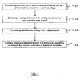
- Fig. 4 shows a flowchart of an embodiment of the method for detecting an operating condition of an electric stepper motor according to the present invention.
- step S1 during a non-activated state of the driving coil, a contact pin P, M of at least one of the electromagnetical driving coils is connected via a high-impedance resistor R1, R2 to a defined voltage source.
- step S2 a voltage induced at the driving coil during the non-activated state is detected and in subsequent step S3 converted by an analog-digital-converter into a digital signal.
- step S4 the digital signal is analyzed and an operating condition of the rotor is determined by evaluation of the signal waveform including positive and negative components of the signal.
- the algorithm performed during the analyzing step S4 processes the sampled data in a standard digital signal processor (which is known as such to the skilled person and therefore not shown in the figures nor described in the specification) preferably evaluates the signal amplitude, phase of positive and negative pulses as well as differential and integral characteristics to build up a so called "Form Factor" value.
- a standard digital signal processor which is known as such to the skilled person and therefore not shown in the figures nor described in the specification
- a standard digital signal processor preferably evaluates the signal amplitude, phase of positive and negative pulses as well as differential and integral characteristics to build up a so called "Form Factor" value.
- Different types of stepper motors can have different characteristics for which the algorithm can be adapted by corresponding programming the digital signal processing circuitry without changing any hardware components.
- the measurement device according to the present invention can therefore be flexibly used for different types of stepper motors such that cost reductions due to larger manufacturing volumes can be realized.
- the normal rotation of the rotor results in a large Form Factor.
- a stalled rotor generates a small Form Factor. If the Form Factor falls below an application specific threshold, the stall event is detected.
- the position of the rotor is known by the last step that was done and thus allows precise zero point alignment of the rotor.
- the usage of the Form Factor has advantages with respect to the commonly used method of applying a simple threshold value for the amplitude of the induced voltage because more waveform characteristics and in particular both polarities of the induced voltage are included for stall detection. For some stepper motor types a simple threshold is even not applicable for distinguishing regular rotation from the stall event.
- the whole induced AC signal can be measured. Neither over- nor undershoots are clipped. Therefore forward as well as backward movements of the rotor can be measured and the analyzed Form Factor has a higher significance.
- the waveform of the obtained signal directly represents the movement speed and direction of the rotor. With each new full step the rotor is attracted to the next magnetic pole generated by the conducting coil. Due to the inertia of the rotor (and additional mechanical parts connected to it), it does not directly stop at the centre of the stator pole. It "overshoots" this position at first, moves back, overshoots again, moves forward, and so on.
- the voltage signal therefore shows a more or less damped oscillation depending on the motor type and rotor load.
- the circuit configuration of Fig. 3a can in addition be used for an automatic calibration at the beginning of a stall detection by measuring the DC offset level to handle variations of hardware components as well as external influences like temperature drift.
- the difference V A between them can be used to check the proper connection of the stepper motor coils.
- Non-connected and high-resistance connections can be detected without the need to drive the stepper motor.
- the series coil resistance can be regarded as short circuit between these two pins, because R 1 ,R 2 >> R S .
- the voltage V A now is nearly zero and indicates a proper connection.
- the resistance between points P and M can be regarded as infinite.
- R 1 pulls up the voltage on ADC P to VDD, while R 2 pulls down ADC M to GND level.
- a voltage difference of V A ⁇ VDD can be measured, indicating a connection error. Voltage differences between the above mentioned states may indicate high impedance connections or damaged stepper motor coils.
- Fig. 5 schematically illustrates a stepping scheme for two phases/coils. It shows the driving voltage sequence ("VDD", “GND”) and the unpowered states ("High-Z").
- VDD driving voltage sequence
- GND ground-to-noise-ratio
- the induced voltage is measured with one of the above described measurement circuits. If the measurement is done single-ended, only one point per coil is measured (for example P1, P2).
- the contact pins M1, M2 are also connected.
- the time duration of each step is an application specific setting. It depends on the strength of the BEMF of the respective stepper motor. The time must be long enough to derive a good signal-to-noise-ratio of the measured induced voltage.
- Figs. 6a and 6b show voltage measurement results at the connection pins P and M of coils A and B of a two-phase stepper motor in different operating conditions using the circuit arrangement according to the invention as shown in Fig. 3 .
- the voltage signal is continuously sampled by the ADC with each electrical step.
- the control unit measures a characteristic signal similar to the High-Z steps shown in Fig. 6a marked 'RUN'. If the rotor reaches the stall position, the movement of the rotor is damped or completely blocked, resulting in a strongly reduced signal (see High-Z steps of coil B in Fig. 6b marked 'STALL').
- the algorithm for processing the sampled waveform may qualify the signal amplitude, polarity of the peaks, integrating and differentiating behaviour in a characteristic "Form Factor" value.
- the algorithm is adapted such way that only the necessary calculations have to be done.
- this Form Factor falls below an application specific threshold and triggers the stall event.
- the position of the rotor is known by the last step that was done and thus allows precise zero point alignment of the rotor of the stepper motor.
Landscapes
- Engineering & Computer Science (AREA)
- Power Engineering (AREA)
- Control Of Stepping Motors (AREA)
Claims (15)
- Procédé de détection d'un état de fonctionnement d'un moteur pas-à-pas électrique, lequel moteur comprend un rotor magnétique et au moins deux bobines d'actionnement électromagnétiques destinées à commander la rotation du rotor conformément à une configuration pas-à-pas, le procédé comprenant, pour chaque pas de la configuration pas-à-pas, :la connexion d'une broche de contact (P, M) d'au moins une des bobines d'actionnement électromagnétiques, laquelle est dans un état non activé pour le pas concerné, à une source de tension définie via une résistance de haute impédance (R1, R2) pendant cet état non-état activé afin d'imposer à cette bobine particulière une tension offset continue fixe à laquelle une tension alternative induite se superpose de façon à pouvoir mesurer une tension simple alternance, la tension offset continue se situant dans la plage d'entrée d'un convertisseur analogique-numérique afin de pouvoir détecter les deux tensions positive et négative ;l'emploi dudit convertisseur analogique-numérique pour détecter une tension induite au niveau de la bobine d'actionnement particulière par une telle mesure simple alternance pendant ledit état non activé et pour convertir la tension détectée en un signal numérique ; etl'analyse numérique du signal numérique par l'évaluation de la forme d'onde du signal incluant des composantes positives et négatives du signal afin de générer une valeur de facteur de forme, et la déduction d'un état de fonctionnement du rotor en utilisant la valeur du facteur de forme par rapport à un seuil spécifique à une application programmée.
- Procédé selon la revendication 1, dans lequel, lorsque le facteur de forme devient inférieur au seuil spécifique à une application programmée, l'état de fonctionnement est un état de blocage du moteur électrique pas-à-pas.
- Procédé selon la revendication 1 ou 2, dans lequel une broche de contact (P) de la bobine d'actionnement particulière pour le pas en question est connectée à une tension de fonctionnement (VDD) par le biais d'une première résistance de haute impédance (R1) et l'autre broche de contact (M) est connectée à la tension de masse (GND) par le biais d'une seconde résistance de haute impédance (R2) pendant ledit état non activé de cette bobine d'actionnement.
- Procédé selon la revendication 3, dans lequel la tension induite au niveau de la bobine d'actionnement particulière pour le pas en question pendant l'état non activé est mesurée entre l'une de ses broches de contact (P, M) et la tension de masse (GND).
- Procédé selon la revendication 3, dans lequel la tension induite au niveau de la bobine d'actionnement particulière pour le pas en question durant l'état non activé est mesurée entre les deux broches de contact (P, M) de ladite bobine d'actionnement.
- Procédé selon la revendication 1 ou 2, dans lequel une broche de contact (P) de la bobine d'actionnement particulière pour le pas en question est connectée à une tension de fonctionnement (VDD) par le biais d'une première résistance de haute impédance (R1) et à la tension de masse (GND) par le biais d'une seconde résistance de haute impédance (R2) pendant l'état non-activé de ladite bobine d'actionnement, et dans lequel la tension induite au niveau de cette bobine d'actionnement est mesurée entre l'autre broche de contact (M) et la tension de masse (GND).
- Procédé selon l'une quelconque des revendications 1 à 6, dans lequel l'étape d'analyse numérique du signal comprend l'obtention de valeurs de signal minimales et/ou maximales, d'une polarité d'impulsion et/ou de caractéristiques d'intégration ou de différenciation du signal.
- Procédé selon l'une quelconque des revendications 1 à 7, comprenant en outre une étape de diagnostic d'erreurs du moteur électrique pas-à-pas, dans laquelle une tension continue au niveau de la bobine d'actionnement est détectée dans un état non activé de celle-ci.
- Procédé selon l'une quelconque des revendications précédentes, comprenant l'analyse numérique du signal numérique afin de générer la valeur du facteur de forme par l'évaluation de la forme d'onde du signal incluant, en fonction du type de moteur, une ou plusieurs composantes positives et négatives, comme l'amplitude et de la phase, du signal et des caractéristiques intégrales et différentielles.
- Procédé selon l'une quelconque des revendications précédentes, comprenant la connexion de ladite broche de contact (P, M) à ladite tension définie par le biais de ladite résistance de haute impédance (R1, R2), en plus de la commutation de ladite broche en mode d'entrée à haute impédance.
- Dispositif de détection pour détecter un état de fonctionnement d'un moteur électrique pas-à-pas, lequel moteur comprend un rotor magnétique et au moins deux bobines d'actionnement électromagnétiques destinées à commander la rotation du rotor conformément à une configuration pas-à-pas, le dispositif de détection comprenant :des moyens opérants, pour chaque pas de la configuration pas-à-pas, pour connecter une résistance de haute impédance (R1, R2) entre une broche de contact (P, M) d'au moins une des bobines d'actionnement électromagnétiques, qui est dans un état non activé pour le pas en question, et une source de tension définie afin d'imposer à cette bobine particulière une tension offset continue fixe à laquelle une tension alternative induite se superpose de façon à pouvoir mesurer une tension simple alternance, la tension offset continue se situant dans la plage d'entrée d'un convertisseur analogique-numérique afin de pouvoir détecter les deux tensions positive et négative,ledit convertisseur analogique-numérique (ADC) adapté, pour chaque pas de la configuration pas-à-pas, pour convertir une tension induite détectée au niveau de la bobine d'actionnement particulière par une telle mesure simple alternance pour le pas en question pendant l'état non activé en un signal numérique, etun processeur de signal numérique adapté, pour chaque pas de la configuration pas-à-pas, pour analyser numériquement le signal numérique par l'évaluation de la forme d'onde du signal incluant des composantes positives et négatives du signal pour générer une valeur de facteur de forme, et pour déduire un état de fonctionnement du rotor en utilisant la valeur du facteur de forme par rapport à un seuil spécifique à une application programmée.
- Dispositif de détection selon la revendication 11, dans lequel, lorsque le facteur de forme devient inférieur au seuil spécifique à une application programmée, l'état de fonctionnement est un état de blocage du moteur électrique pas-à-pas.
- Dispositif de détection selon la revendication 11 ou 12, opérant, pour chaque pas de la configuration pas-à-pas, pour connecter une broche de contact (P) de la bobine d'actionnement particulière pour le pas en question à une tension de fonctionnement (VDD) par le biais d'une première résistance de haute impédance (R1) et l'autre broche de contact (M) à la tension de masse (GND) par le biais d'une seconde résistance de haute impédance (R2) pendant l'état non activé de cette bobine d'actionnement.
- Dispositif de détection selon la revendication 11 ou 12, opérant, pour chaque pas de la configuration pas-à-pas, pour connecter une broche de contact (P) de la bobine d'actionnement particulière pour le pas en question à une tension de fonctionnement (VDD) par le biais d'une première résistance de haute impédance (R1) et à la tension de masse (GND) par le biais d'une seconde résistance de haute impédance (R2) pendant l'état non activé de cette bobine d'actionnement.
- Dispositif de détection selon l'une quelconque des revendications 11 à 14, dans lequel le processeur de signal numérique est adapté pour analyser numériquement le signal numérique afin de générer la valeur du facteur de forme par l'évaluation de la forme d'onde du signal incluant, en fonction du type de moteur, une ou plusieurs composantes positive et négative, comme l'amplitude et la phase, du signal et des caractéristiques intégrales et différentielles.
Applications Claiming Priority (1)
| Application Number | Priority Date | Filing Date | Title |
|---|---|---|---|
| PCT/EP2008/065314 WO2010054680A1 (fr) | 2008-11-11 | 2008-11-11 | Procédé de détection d'une condition de fonctionnement d'un moteur pas à pas électrique |
Publications (2)
| Publication Number | Publication Date |
|---|---|
| EP2345148A1 EP2345148A1 (fr) | 2011-07-20 |
| EP2345148B1 true EP2345148B1 (fr) | 2014-09-03 |
Family
ID=40821804
Family Applications (1)
| Application Number | Title | Priority Date | Filing Date |
|---|---|---|---|
| EP08875304.1A Not-in-force EP2345148B1 (fr) | 2008-11-11 | 2008-11-11 | Procédé de détection d'une condition de fonctionnement d'un moteur pas à pas électrique |
Country Status (5)
| Country | Link |
|---|---|
| US (1) | US8841874B2 (fr) |
| EP (1) | EP2345148B1 (fr) |
| JP (1) | JP5400167B2 (fr) |
| CN (1) | CN102210093B (fr) |
| WO (1) | WO2010054680A1 (fr) |
Families Citing this family (7)
| Publication number | Priority date | Publication date | Assignee | Title |
|---|---|---|---|---|
| DE102008043103A1 (de) * | 2008-10-22 | 2010-04-29 | Alstrom Technology Ltd. | Vorrichtung und Verfahren zur Überwachung und/oder Analyse von Rotoren von elektrischen Maschinen im Betrieb |
| DE102012211577A1 (de) * | 2012-07-04 | 2014-01-09 | Robert Bosch Gmbh | Leistungsendstufe, Verfahren zum Betreiben |
| WO2014006455A1 (fr) * | 2012-07-06 | 2014-01-09 | Freescale Semiconductor, Inc. | Dispositif électronique pour détection de proximité, diode électroluminescente pour un tel dispositif électronique, unité de commande pour un tel dispositif électronique, appareil comprenant un tel dispositif électronique et procédé associé |
| JP2015061467A (ja) | 2013-09-20 | 2015-03-30 | カシオ計算機株式会社 | ステッピングモータ及び時計 |
| DE102015211216A1 (de) * | 2015-06-18 | 2016-12-22 | Robert Bosch Gmbh | Verfahren und Schaltung zum Erkennen eines Kurzschlusses der Sinus- oder Kosinus-Empfängerspule eines Resolvers |
| EP3291438B1 (fr) * | 2016-08-30 | 2021-11-10 | Valeo Klimasysteme GmbH | Procédé de détection de blocage d'un moteur pas à pas électrique, moteur pas à pas électrique et dispositif de chauffage, de ventilation et/ou un système de climatisation comprenant un moteur pas à pas électrique |
| RU2713224C1 (ru) * | 2019-02-05 | 2020-02-04 | Акционерное общество "Корпорация "Московский институт теплотехники" (АО "Корпорация "МИТ") | Способ определения момента достижения механического упора электроприводом с биполярным шаговым двигателем и устройство для его осуществления |
Family Cites Families (24)
| Publication number | Priority date | Publication date | Assignee | Title |
|---|---|---|---|---|
| JPS58154398A (ja) * | 1982-03-08 | 1983-09-13 | Fuji Xerox Co Ltd | ステツプモ−タの励磁回路 |
| DE3404127A1 (de) * | 1984-02-07 | 1985-08-14 | Berger Lahr GmbH, 7630 Lahr | Steuerschaltung fuer einen schrittmotor |
| US4684866A (en) * | 1986-04-16 | 1987-08-04 | General Motors Corporation | Adaptive controller for a motor vehicle engine throttle operator |
| SE455034B (sv) * | 1986-10-10 | 1988-06-13 | Ems Electronic Motor Systems | Drivkrets for en reluktansmotor |
| US4851755A (en) * | 1988-03-01 | 1989-07-25 | Ampex Corporation | Low power stepper motor drive system and method |
| DE3921462A1 (de) | 1989-02-14 | 1990-08-16 | Vdo Schindling | Verfahren und schaltungsanordnung zum betrieb eines schrittmotors |
| US5072166A (en) * | 1990-06-18 | 1991-12-10 | The Texas A&M University System | Position sensor elimination technique for the switched reluctance motor drive |
| DE4200551A1 (de) | 1992-01-11 | 1993-07-15 | Vdo Schindling | Synchronisierverfahren fuer ein anzeigegeraet mit elektrisch angesteuertem schrittmotor |
| US5264770A (en) * | 1992-03-12 | 1993-11-23 | Coutu David J | Stepper motor driver circuit |
| JPH0833398A (ja) | 1994-07-22 | 1996-02-02 | Fuji Electric Co Ltd | パルスモータの回転監視方法 |
| JP3724048B2 (ja) * | 1995-11-06 | 2005-12-07 | 株式会社デンソー | L負荷駆動装置 |
| FR2795886B1 (fr) * | 1999-06-29 | 2001-10-05 | Sonceboz Sa | Methode de calage d'un moteur electrique de type polyphase a fonctionnement pas a pas, ceci par rapport a une position de reference correspondant a une butee mecanique |
| US6611072B1 (en) | 1999-11-17 | 2003-08-26 | Parker-Hannifin Corporation | Sensorless stall detection for motors |
| US6861817B2 (en) | 2001-12-21 | 2005-03-01 | Freescale Semiconductor, Inc. | Method and apparatus for detecting a stall condition in a stepping motor |
| JP4209724B2 (ja) * | 2003-06-25 | 2009-01-14 | 矢崎総業株式会社 | ステッパモータの駆動装置 |
| US6900657B2 (en) * | 2003-09-24 | 2005-05-31 | Saia-Burgess Automotive, Inc. | Stall detection circuit and method |
| JP4267424B2 (ja) * | 2003-10-31 | 2009-05-27 | 矢崎総業株式会社 | ステッパモータの駆動装置 |
| FR2861924B1 (fr) | 2003-11-03 | 2007-02-02 | Moving Magnet Tech | Procede pour la detection de butees et de calage d'un moteur pas-a-pas et moteur pas-a-pas a detecteur de butee |
| US6979972B2 (en) | 2003-12-30 | 2005-12-27 | Xerox Corporation | Method and apparatus for detecting a stalled stepper motor |
| JP4520204B2 (ja) * | 2004-04-14 | 2010-08-04 | 三菱電機株式会社 | 高周波電力増幅器 |
| US7224140B2 (en) | 2005-01-31 | 2007-05-29 | Texas Instruments Incorporated | Method of stall detection for stepper motor system |
| EP1760875A1 (fr) * | 2005-08-30 | 2007-03-07 | Protronic N.V. | Procédé et dispositif détectant l'état d'opération d'un moteur |
| EP2068436B1 (fr) * | 2007-12-03 | 2013-07-17 | Roche Diagnostics GmbH | Procédé et dispositif destinés à détecter les pertes de pas d'un moteur pas à pas |
| US7705555B2 (en) * | 2007-12-18 | 2010-04-27 | Freescale Semiconductor, Inc. | Method and controller for detecting a stall condition in a stepping motor during micro-stepping |
-
2008
- 2008-11-11 WO PCT/EP2008/065314 patent/WO2010054680A1/fr not_active Ceased
- 2008-11-11 US US13/125,462 patent/US8841874B2/en active Active
- 2008-11-11 EP EP08875304.1A patent/EP2345148B1/fr not_active Not-in-force
- 2008-11-11 JP JP2011535882A patent/JP5400167B2/ja active Active
- 2008-11-11 CN CN200880131951.5A patent/CN102210093B/zh active Active
Also Published As
| Publication number | Publication date |
|---|---|
| JP2012508559A (ja) | 2012-04-05 |
| CN102210093B (zh) | 2015-02-11 |
| US8841874B2 (en) | 2014-09-23 |
| EP2345148A1 (fr) | 2011-07-20 |
| JP5400167B2 (ja) | 2014-01-29 |
| CN102210093A (zh) | 2011-10-05 |
| US20120019186A1 (en) | 2012-01-26 |
| WO2010054680A1 (fr) | 2010-05-20 |
Similar Documents
| Publication | Publication Date | Title |
|---|---|---|
| EP2345148B1 (fr) | Procédé de détection d'une condition de fonctionnement d'un moteur pas à pas électrique | |
| US8917044B2 (en) | Electronic circuit and method for detecting a zero current in a winding of an electric motor | |
| US8917043B2 (en) | Electronic circuit and method for automatically adjusting a phase of a drive signal applied to an electric motor in accordance with a zero current detected in a winding of the electric motor | |
| CN1319266C (zh) | 检测在步进马达中的停转状态的方法和设备 | |
| KR101748188B1 (ko) | 스텝 로스 조건을 검출하기 위한 방법 | |
| US7902775B2 (en) | Motor driving device | |
| US7334854B1 (en) | Sensorless start-up method for driving a brushless DC motor | |
| CN112088486B (zh) | 马达的操作模式控制 | |
| US7288956B2 (en) | Device and method for detecting rotor speed of a multiple phase motor with bipolar drive | |
| CN113474988B (zh) | 具有精确电流测量功能的电机控制器 | |
| CN109247054B (zh) | 用于测量步进电机的反电动势的方法和设备及集成电路 | |
| KR101899014B1 (ko) | 비엘디씨 모터의 제어 장치 및 그 방법 | |
| EP1983644A2 (fr) | Détection d'orientation de rotor dans des moteurs CC sans balai | |
| JP5503004B2 (ja) | 同期機械のロータ位置を検出するための方法と装置 | |
| US6771480B2 (en) | Circuit to sample and compare the BEMF on an actuator into a constant velocity control | |
| JP5535226B2 (ja) | 直流電動機、および、直流電動機の駆動方法 | |
| US9379650B2 (en) | Enhanced inductive sense using mutual inductance | |
| US9991827B1 (en) | Methods and apparatus for automatic lead angle adjustment using fly-back voltage for brushless DC control | |
| KR101967459B1 (ko) | 3상 모터의 홀센서 에러 검출 방법 및 3상 모터 제어 장치 | |
| JPH0799796A (ja) | ステッピングモータの駆動装置 | |
| JP2002354893A (ja) | ステップモータの回転制御装置 | |
| CN115963865B (zh) | 一种电机磁极位置校准的系统及方法 | |
| CN109429544B (zh) | 用于确定电动机位置的方法和系统 | |
| CN116707362A (zh) | 单相直流电机控制方法、单元、系统及芯片 | |
| CN119945243A (zh) | 转子初始位置的检测方法、程序产品和无刷直流电机系统 |
Legal Events
| Date | Code | Title | Description |
|---|---|---|---|
| PUAI | Public reference made under article 153(3) epc to a published international application that has entered the european phase |
Free format text: ORIGINAL CODE: 0009012 |
|
| 17P | Request for examination filed |
Effective date: 20110606 |
|
| AK | Designated contracting states |
Kind code of ref document: A1 Designated state(s): AT BE BG CH CY CZ DE DK EE ES FI FR GB GR HR HU IE IS IT LI LT LU LV MC MT NL NO PL PT RO SE SI SK TR |
|
| AX | Request for extension of the european patent |
Extension state: AL BA MK RS |
|
| DAX | Request for extension of the european patent (deleted) | ||
| 17Q | First examination report despatched |
Effective date: 20120606 |
|
| RAP1 | Party data changed (applicant data changed or rights of an application transferred) |
Owner name: SPANSION LLC |
|
| GRAP | Despatch of communication of intention to grant a patent |
Free format text: ORIGINAL CODE: EPIDOSNIGR1 |
|
| RIC1 | Information provided on ipc code assigned before grant |
Ipc: H02P 8/34 20060101AFI20131206BHEP |
|
| INTG | Intention to grant announced |
Effective date: 20140108 |
|
| GRAP | Despatch of communication of intention to grant a patent |
Free format text: ORIGINAL CODE: EPIDOSNIGR1 |
|
| INTG | Intention to grant announced |
Effective date: 20140326 |
|
| GRAS | Grant fee paid |
Free format text: ORIGINAL CODE: EPIDOSNIGR3 |
|
| GRAA | (expected) grant |
Free format text: ORIGINAL CODE: 0009210 |
|
| AK | Designated contracting states |
Kind code of ref document: B1 Designated state(s): AT BE BG CH CY CZ DE DK EE ES FI FR GB GR HR HU IE IS IT LI LT LU LV MC MT NL NO PL PT RO SE SI SK TR |
|
| REG | Reference to a national code |
Ref country code: GB Ref legal event code: FG4D |
|
| REG | Reference to a national code |
Ref country code: AT Ref legal event code: REF Ref document number: 686043 Country of ref document: AT Kind code of ref document: T Effective date: 20140915 Ref country code: CH Ref legal event code: EP |
|
| REG | Reference to a national code |
Ref country code: IE Ref legal event code: FG4D |
|
| REG | Reference to a national code |
Ref country code: DE Ref legal event code: R096 Ref document number: 602008034282 Country of ref document: DE Effective date: 20141009 |
|
| REG | Reference to a national code |
Ref country code: AT Ref legal event code: MK05 Ref document number: 686043 Country of ref document: AT Kind code of ref document: T Effective date: 20140903 |
|
| PG25 | Lapsed in a contracting state [announced via postgrant information from national office to epo] |
Ref country code: LT Free format text: LAPSE BECAUSE OF FAILURE TO SUBMIT A TRANSLATION OF THE DESCRIPTION OR TO PAY THE FEE WITHIN THE PRESCRIBED TIME-LIMIT Effective date: 20140903 Ref country code: GR Free format text: LAPSE BECAUSE OF FAILURE TO SUBMIT A TRANSLATION OF THE DESCRIPTION OR TO PAY THE FEE WITHIN THE PRESCRIBED TIME-LIMIT Effective date: 20141204 Ref country code: SE Free format text: LAPSE BECAUSE OF FAILURE TO SUBMIT A TRANSLATION OF THE DESCRIPTION OR TO PAY THE FEE WITHIN THE PRESCRIBED TIME-LIMIT Effective date: 20140903 Ref country code: FI Free format text: LAPSE BECAUSE OF FAILURE TO SUBMIT A TRANSLATION OF THE DESCRIPTION OR TO PAY THE FEE WITHIN THE PRESCRIBED TIME-LIMIT Effective date: 20140903 Ref country code: NO Free format text: LAPSE BECAUSE OF FAILURE TO SUBMIT A TRANSLATION OF THE DESCRIPTION OR TO PAY THE FEE WITHIN THE PRESCRIBED TIME-LIMIT Effective date: 20141203 Ref country code: ES Free format text: LAPSE BECAUSE OF FAILURE TO SUBMIT A TRANSLATION OF THE DESCRIPTION OR TO PAY THE FEE WITHIN THE PRESCRIBED TIME-LIMIT Effective date: 20140903 |
|
| REG | Reference to a national code |
Ref country code: NL Ref legal event code: VDEP Effective date: 20140903 |
|
| REG | Reference to a national code |
Ref country code: LT Ref legal event code: MG4D |
|
| PG25 | Lapsed in a contracting state [announced via postgrant information from national office to epo] |
Ref country code: AT Free format text: LAPSE BECAUSE OF FAILURE TO SUBMIT A TRANSLATION OF THE DESCRIPTION OR TO PAY THE FEE WITHIN THE PRESCRIBED TIME-LIMIT Effective date: 20140903 Ref country code: CY Free format text: LAPSE BECAUSE OF FAILURE TO SUBMIT A TRANSLATION OF THE DESCRIPTION OR TO PAY THE FEE WITHIN THE PRESCRIBED TIME-LIMIT Effective date: 20140903 Ref country code: HR Free format text: LAPSE BECAUSE OF FAILURE TO SUBMIT A TRANSLATION OF THE DESCRIPTION OR TO PAY THE FEE WITHIN THE PRESCRIBED TIME-LIMIT Effective date: 20140903 Ref country code: LV Free format text: LAPSE BECAUSE OF FAILURE TO SUBMIT A TRANSLATION OF THE DESCRIPTION OR TO PAY THE FEE WITHIN THE PRESCRIBED TIME-LIMIT Effective date: 20140903 |
|
| PG25 | Lapsed in a contracting state [announced via postgrant information from national office to epo] |
Ref country code: NL Free format text: LAPSE BECAUSE OF FAILURE TO SUBMIT A TRANSLATION OF THE DESCRIPTION OR TO PAY THE FEE WITHIN THE PRESCRIBED TIME-LIMIT Effective date: 20140903 |
|
| PG25 | Lapsed in a contracting state [announced via postgrant information from national office to epo] |
Ref country code: IS Free format text: LAPSE BECAUSE OF FAILURE TO SUBMIT A TRANSLATION OF THE DESCRIPTION OR TO PAY THE FEE WITHIN THE PRESCRIBED TIME-LIMIT Effective date: 20150103 Ref country code: PT Free format text: LAPSE BECAUSE OF FAILURE TO SUBMIT A TRANSLATION OF THE DESCRIPTION OR TO PAY THE FEE WITHIN THE PRESCRIBED TIME-LIMIT Effective date: 20150105 Ref country code: CZ Free format text: LAPSE BECAUSE OF FAILURE TO SUBMIT A TRANSLATION OF THE DESCRIPTION OR TO PAY THE FEE WITHIN THE PRESCRIBED TIME-LIMIT Effective date: 20140903 Ref country code: EE Free format text: LAPSE BECAUSE OF FAILURE TO SUBMIT A TRANSLATION OF THE DESCRIPTION OR TO PAY THE FEE WITHIN THE PRESCRIBED TIME-LIMIT Effective date: 20140903 Ref country code: RO Free format text: LAPSE BECAUSE OF FAILURE TO SUBMIT A TRANSLATION OF THE DESCRIPTION OR TO PAY THE FEE WITHIN THE PRESCRIBED TIME-LIMIT Effective date: 20140903 Ref country code: SK Free format text: LAPSE BECAUSE OF FAILURE TO SUBMIT A TRANSLATION OF THE DESCRIPTION OR TO PAY THE FEE WITHIN THE PRESCRIBED TIME-LIMIT Effective date: 20140903 |
|
| PG25 | Lapsed in a contracting state [announced via postgrant information from national office to epo] |
Ref country code: PL Free format text: LAPSE BECAUSE OF FAILURE TO SUBMIT A TRANSLATION OF THE DESCRIPTION OR TO PAY THE FEE WITHIN THE PRESCRIBED TIME-LIMIT Effective date: 20140903 |
|
| REG | Reference to a national code |
Ref country code: DE Ref legal event code: R097 Ref document number: 602008034282 Country of ref document: DE |
|
| PG25 | Lapsed in a contracting state [announced via postgrant information from national office to epo] |
Ref country code: MC Free format text: LAPSE BECAUSE OF FAILURE TO SUBMIT A TRANSLATION OF THE DESCRIPTION OR TO PAY THE FEE WITHIN THE PRESCRIBED TIME-LIMIT Effective date: 20140903 Ref country code: BE Free format text: LAPSE BECAUSE OF NON-PAYMENT OF DUE FEES Effective date: 20141130 Ref country code: LU Free format text: LAPSE BECAUSE OF FAILURE TO SUBMIT A TRANSLATION OF THE DESCRIPTION OR TO PAY THE FEE WITHIN THE PRESCRIBED TIME-LIMIT Effective date: 20141111 |
|
| REG | Reference to a national code |
Ref country code: CH Ref legal event code: PL |
|
| PLBE | No opposition filed within time limit |
Free format text: ORIGINAL CODE: 0009261 |
|
| STAA | Information on the status of an ep patent application or granted ep patent |
Free format text: STATUS: NO OPPOSITION FILED WITHIN TIME LIMIT |
|
| REG | Reference to a national code |
Ref country code: GB Ref legal event code: 732E Free format text: REGISTERED BETWEEN 20150618 AND 20150624 |
|
| REG | Reference to a national code |
Ref country code: DE Ref legal event code: R082 Ref document number: 602008034282 Country of ref document: DE Representative=s name: MURGITROYD & COMPANY, DE Ref country code: DE Ref legal event code: R081 Ref document number: 602008034282 Country of ref document: DE Owner name: CYPRESS SEMICONDUCTOR CORP. (N.D.GES.D.STAATES, US Free format text: FORMER OWNER: SPANSION LLC, SUNNYVALE, CALIF., US |
|
| PG25 | Lapsed in a contracting state [announced via postgrant information from national office to epo] |
Ref country code: LI Free format text: LAPSE BECAUSE OF NON-PAYMENT OF DUE FEES Effective date: 20141130 Ref country code: CH Free format text: LAPSE BECAUSE OF NON-PAYMENT OF DUE FEES Effective date: 20141130 Ref country code: DK Free format text: LAPSE BECAUSE OF FAILURE TO SUBMIT A TRANSLATION OF THE DESCRIPTION OR TO PAY THE FEE WITHIN THE PRESCRIBED TIME-LIMIT Effective date: 20140903 |
|
| 26N | No opposition filed |
Effective date: 20150604 |
|
| REG | Reference to a national code |
Ref country code: IE Ref legal event code: MM4A |
|
| PG25 | Lapsed in a contracting state [announced via postgrant information from national office to epo] |
Ref country code: IT Free format text: LAPSE BECAUSE OF FAILURE TO SUBMIT A TRANSLATION OF THE DESCRIPTION OR TO PAY THE FEE WITHIN THE PRESCRIBED TIME-LIMIT Effective date: 20140903 |
|
| PG25 | Lapsed in a contracting state [announced via postgrant information from national office to epo] |
Ref country code: IE Free format text: LAPSE BECAUSE OF NON-PAYMENT OF DUE FEES Effective date: 20141111 |
|
| PG25 | Lapsed in a contracting state [announced via postgrant information from national office to epo] |
Ref country code: SI Free format text: LAPSE BECAUSE OF FAILURE TO SUBMIT A TRANSLATION OF THE DESCRIPTION OR TO PAY THE FEE WITHIN THE PRESCRIBED TIME-LIMIT Effective date: 20140903 |
|
| REG | Reference to a national code |
Ref country code: FR Ref legal event code: PLFP Year of fee payment: 8 |
|
| REG | Reference to a national code |
Ref country code: FR Ref legal event code: TP Owner name: CYPRESS SEMICONDUCTOR CORPORATION, US Effective date: 20151124 |
|
| PG25 | Lapsed in a contracting state [announced via postgrant information from national office to epo] |
Ref country code: BG Free format text: LAPSE BECAUSE OF FAILURE TO SUBMIT A TRANSLATION OF THE DESCRIPTION OR TO PAY THE FEE WITHIN THE PRESCRIBED TIME-LIMIT Effective date: 20140903 |
|
| PG25 | Lapsed in a contracting state [announced via postgrant information from national office to epo] |
Ref country code: HU Free format text: LAPSE BECAUSE OF FAILURE TO SUBMIT A TRANSLATION OF THE DESCRIPTION OR TO PAY THE FEE WITHIN THE PRESCRIBED TIME-LIMIT; INVALID AB INITIO Effective date: 20081111 Ref country code: MT Free format text: LAPSE BECAUSE OF FAILURE TO SUBMIT A TRANSLATION OF THE DESCRIPTION OR TO PAY THE FEE WITHIN THE PRESCRIBED TIME-LIMIT Effective date: 20140903 Ref country code: TR Free format text: LAPSE BECAUSE OF FAILURE TO SUBMIT A TRANSLATION OF THE DESCRIPTION OR TO PAY THE FEE WITHIN THE PRESCRIBED TIME-LIMIT Effective date: 20140903 Ref country code: BE Free format text: LAPSE BECAUSE OF FAILURE TO SUBMIT A TRANSLATION OF THE DESCRIPTION OR TO PAY THE FEE WITHIN THE PRESCRIBED TIME-LIMIT Effective date: 20140903 |
|
| REG | Reference to a national code |
Ref country code: FR Ref legal event code: PLFP Year of fee payment: 9 |
|
| REG | Reference to a national code |
Ref country code: FR Ref legal event code: PLFP Year of fee payment: 10 |
|
| PGFP | Annual fee paid to national office [announced via postgrant information from national office to epo] |
Ref country code: FR Payment date: 20170428 Year of fee payment: 10 |
|
| PG25 | Lapsed in a contracting state [announced via postgrant information from national office to epo] |
Ref country code: FR Free format text: LAPSE BECAUSE OF NON-PAYMENT OF DUE FEES Effective date: 20181130 |
|
| REG | Reference to a national code |
Ref country code: DE Ref legal event code: R082 Ref document number: 602008034282 Country of ref document: DE Representative=s name: GRAF VON KEYSERLINGK, ALBERT, DIPL.-ING.- DIPL, DE |
|
| P01 | Opt-out of the competence of the unified patent court (upc) registered |
Effective date: 20230528 |
|
| PGFP | Annual fee paid to national office [announced via postgrant information from national office to epo] |
Ref country code: GB Payment date: 20231123 Year of fee payment: 16 |
|
| PGFP | Annual fee paid to national office [announced via postgrant information from national office to epo] |
Ref country code: DE Payment date: 20231121 Year of fee payment: 16 |
|
| REG | Reference to a national code |
Ref country code: DE Ref legal event code: R119 Ref document number: 602008034282 Country of ref document: DE |
|
| GBPC | Gb: european patent ceased through non-payment of renewal fee |
Effective date: 20241111 |
|
| PG25 | Lapsed in a contracting state [announced via postgrant information from national office to epo] |
Ref country code: DE Free format text: LAPSE BECAUSE OF NON-PAYMENT OF DUE FEES Effective date: 20250603 |
|
| PG25 | Lapsed in a contracting state [announced via postgrant information from national office to epo] |
Ref country code: GB Free format text: LAPSE BECAUSE OF NON-PAYMENT OF DUE FEES Effective date: 20241111 |