EP2345345A1 - Chaise dotée d'un dossier inclinable - Google Patents
Chaise dotée d'un dossier inclinable Download PDFInfo
- Publication number
- EP2345345A1 EP2345345A1 EP10425009A EP10425009A EP2345345A1 EP 2345345 A1 EP2345345 A1 EP 2345345A1 EP 10425009 A EP10425009 A EP 10425009A EP 10425009 A EP10425009 A EP 10425009A EP 2345345 A1 EP2345345 A1 EP 2345345A1
- Authority
- EP
- European Patent Office
- Prior art keywords
- backrest
- fixed
- base structure
- axis
- chair
- Prior art date
- Legal status (The legal status is an assumption and is not a legal conclusion. Google has not performed a legal analysis and makes no representation as to the accuracy of the status listed.)
- Withdrawn
Links
Images



Classifications
-
- A—HUMAN NECESSITIES
- A47—FURNITURE; DOMESTIC ARTICLES OR APPLIANCES; COFFEE MILLS; SPICE MILLS; SUCTION CLEANERS IN GENERAL
- A47C—CHAIRS; SOFAS; BEDS
- A47C7/00—Parts, details, or accessories of chairs or stools
- A47C7/36—Supports for the head or the back
- A47C7/40—Supports for the head or the back for the back
- A47C7/44—Supports for the head or the back for the back with elastically-mounted frame
- A47C7/443—Supports for the head or the back for the back with elastically-mounted frame with coil springs
- A47C7/444—Supports for the head or the back for the back with elastically-mounted frame with coil springs of torsion type
Definitions
- the present invention relates to a chair comprising a base structure, a seat carried by the base structure, a backrest articulated to the base structure about a horizontal axis, and an elastic mechanism set between the base structure and the backrest for pushing the backrest elastically towards a resting position.
- the backrest can be reclined backwards, against the return force of the elastic mechanism, by the thrust applied by the user's back and returns into the resting position when the thrust backwards applied by the user ceases.
- the document No. EP-A-0626146 filed in the name of the present applicant describes a chair with tilting backrest having the characteristics specified in the preamble of Claim 1.
- torsion-spring means are provided, which push the backrest towards its resting position.
- the torsion-spring means comprise an elongated torsion element set along the axis of articulation of the backrest to the base structure.
- the torsion element is set within a transverse tubular member fixed to the base structure.
- the object of the present invention is to provide a chair with tilting backrest of the type indicated above that will be lighter both from the purely physical standpoint and from the aesthetic standpoint.
- the above object is achieved by a chair having the characteristics that form the subject of Claim 1.
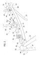
- the chair 10 comprises a base structure 12, carrying a seat 14 and a backrest 16.
- the base structure 12 comprises two front legs 18 and two rear legs 20.
- the front leg 18 and the rear leg 20 on the same side of the chair 10 are joined to one another by means of a longitudinal element 22.
- a transverse element 24 joins the longitudinal elements 22 together in the rear part of the chair.
- the legs 18, 20, the longitudinal elements 22, and the transverse element 24 are constituted by bent metal tubular members that are connected to one another by welding.
- the shape illustrated of the base structure 12 is not, however, imperative, and it is understood that the base structure 12 may assume other shapes.
- the seat 14 can be constituted by a shaped panel made of injection-moulded plastic material fixed to the base structure 12 by coupling by snap-action, using screws, or in any other way.
- the backrest 16 comprises two lateral uprights 26 that carry an arched resting portion 28.
- the uprights 26 and the resting portion 28 are formed in a monolithic way by means of injection moulding.
- the uprights 26 preferably have a tubular shape open downwards.
- the backrest 16 is articulated to the base structure 12 about a horizontal transverse axis A in the way that will be described in what follows.
- the backrest 16 can oscillate about the axis A between a resting position and a position reclined backwards. As will be described better in what follows, the backrest 16 is subjected to an elastic return force that tends to keep it in the resting position and can be reclined backwards under the action of a thrust backwards applied by the user's back.
- the chair 10 comprises an elastic mechanism 30, arranged for pushing the backrest 16 elastically towards its resting position.
- the elastic mechanism 30 comprises two hubs 32 fixed with respect to the base structure 12 and set at a distance from one another in transverse direction along the axis of articulation A.
- each hub 32 is fixed, for example by welding, to the longitudinal element 22 and to the rear leg 20 of the respective side of the chair.
- the elastic mechanism 30 comprises two rotating members 34 coupled in an oscillating way to the respective hubs 32 about the axis A.
- each rotating member 34 has a tubular portion 36 with an axial hole 48 and a disk-shaped flange 38 fixed to one end of the tubular portion 36.
- the rotating members 34 are fixed to the bottom ends of the respective uprights 26 of the backrest 16.
- said fixing is provided by means of respective coupling rods 40, each of which is fixed to the respective disk-shaped flange 38 and is inserted and clamped in the respective upright 26 of the backrest 16.
- each hub 32 has a cylindrical wall 42, a front wall 44, and a pin 46, which extends in cantilever fashion from the bottom wall 44 coaxially to the axis of articulation A.
- the pin 46 of each hub 32 is inserted in the axial hole 48 of a respective rotating member 34.
- a bushing 50 made of a material with low coefficient of friction is set between the external surface of the pin 46 and the internal surface of the hole 48.
- the elastic mechanism 30 comprises two helical springs 52 set coaxially to the axis of articulation A.
- Each helical spring 52 extends on the outside of the tubular portion 36 of the respective rotating member 34.
- Each helical spring 52 has a first end 54 fixed to the respective hub 32 and a second end 56 fixed to the respective rotating member 34.
- the ends 54, 56 are preferably bent in a direction parallel to the axis A and fit within respective holes 58, 60 provided on the hub 32 and on the rotating member 34.
- a second bushing 62 is set between each helical spring 52 and the external surface of the respective tubular portion 36.
- Each rotating member 34 is connected to the respective hub 32 by means of a screw 64, which extends through an axial hole of the respective disk-shaped flange 38 and engages a threaded hole 66 of the pin 46.
- a washer 68 is preferably set between the head of the screw 64 and the external front surface of the respective disk-shaped flange 38.
- the elastic mechanism 30 includes an end-of-travel device that defines the resting position and the position of maximum inclination backwards of the backrest 16.
- said end-of-travel device is provided by means of a tooth 70, projecting axially and fixed with respect to each disk-shaped flange 38, which engages a respective slit 72 formed in the side wall 42 of the respective hub 32.
- the slit 72 has an angular amplitude greater than that of the tooth 70.
- the resting position and the position of maximum inclination backwards of the backrest are defined by the positions of bearing of the tooth 70 upon the opposed ends of the groove 72.
- the fixed hubs 32 are located in an external position, in a transverse direction, with respect to the rotating members 34, and the uprights 26 of the backrest 16 are shifted inwards with respect to the external lateral edges of the seat 14. Consequently, as illustrated in Figure 4 , the coupling bars 40 that connect the uprights 26 of the backrest 16 to the rotating members 34 extend through respective through slits 74 formed in the rear part of the seat 14. The angular amplitude of the slits 74 is greater than the angle of inclination of the backrest 16.
- FIGS. 6 to 8 illustrate a second embodiment of a chair according to the present invention.
- the elements corresponding to the ones described previously are designated by the same reference numbers.
- the rotating members 34 connected to the backrest 16 are set in an outer position in a direction transverse with respect to that of the hubs 32.
- each rotating member 34 has a cylindrical wall 42 and a connection rod 40, which extends, preferably in an integral way, from the cylindrical wall 42.
- the connection rod 40 fits within a respective upright 26 of the backrest 16.
- Each rotating member 34 has a bottom wall 44 extending from which is an axial pin 46, which fits within a hole 48 of a tubular portion 36 of a respective hub 32.
- Each hub 32 has a disk-shaped flange 38, which is fixed, for example by means of welding, to a corresponding longitudinal element 22 of the base structure 12.
- a screw 64 engages a threaded hole 66 formed in the pin 46 of the respective rotating member 34 for connecting each rotating member 34 axially to the respective hub 32.
- the elastic mechanism 30 comprises two helical springs 52 each of which has a first end 54 fixed to the respective hub 32 and a second end 56 fixed to the respective rotating member 34. Also in this case, an end-of-travel device is provided, made in a way similar to what has been described previously with reference to Figure 5 .
Landscapes
- Chairs Characterized By Structure (AREA)
Priority Applications (1)
| Application Number | Priority Date | Filing Date | Title |
|---|---|---|---|
| EP10425009A EP2345345A1 (fr) | 2010-01-15 | 2010-01-15 | Chaise dotée d'un dossier inclinable |
Applications Claiming Priority (1)
| Application Number | Priority Date | Filing Date | Title |
|---|---|---|---|
| EP10425009A EP2345345A1 (fr) | 2010-01-15 | 2010-01-15 | Chaise dotée d'un dossier inclinable |
Publications (1)
| Publication Number | Publication Date |
|---|---|
| EP2345345A1 true EP2345345A1 (fr) | 2011-07-20 |
Family
ID=42110954
Family Applications (1)
| Application Number | Title | Priority Date | Filing Date |
|---|---|---|---|
| EP10425009A Withdrawn EP2345345A1 (fr) | 2010-01-15 | 2010-01-15 | Chaise dotée d'un dossier inclinable |
Country Status (1)
| Country | Link |
|---|---|
| EP (1) | EP2345345A1 (fr) |
Cited By (6)
| Publication number | Priority date | Publication date | Assignee | Title |
|---|---|---|---|---|
| KR101603994B1 (ko) | 2014-03-24 | 2016-03-16 | 성용기업 주식회사 | 코일스프링의 토션력을 이용한 틸팅부가 구비된 틸팅의자 |
| US9754515B2 (en) | 2011-08-08 | 2017-09-05 | Stefano Nicolis | Support for communication elements in points of sale of products |
| KR102129610B1 (ko) * | 2020-05-14 | 2020-07-02 | (주)한솔스틸 | 의자용 틸팅 등받이와 팔걸이 조립체 |
| CN111671261A (zh) * | 2020-06-02 | 2020-09-18 | 周七燕 | 可收叠的靠背凳 |
| CN112374332A (zh) * | 2020-10-30 | 2021-02-19 | 井多明 | 一种电梯轿厢 |
| US20230129979A1 (en) * | 2021-10-27 | 2023-04-27 | Rocking Inc. | Portable rebounding device with adjustable and collapsible features |
Citations (4)
| Publication number | Priority date | Publication date | Assignee | Title |
|---|---|---|---|---|
| DE849478C (de) * | 1950-11-11 | 1952-09-15 | Erste Darmstaedter Karosseriew | Sitz mit verstellbarer Rueckenlehne |
| EP0626146A1 (fr) | 1993-05-27 | 1994-11-30 | PRO-CORD s.r.l. | Chaise avec dossier basculant |
| WO2006096883A2 (fr) * | 2005-03-09 | 2006-09-14 | Bretford Manufacturing, Inc. | Chaise munie d'un dossier de siege auto-reglable |
| WO2007087817A1 (fr) * | 2006-01-12 | 2007-08-09 | Bock 1 Gmbh & Co. Kg | Mecanisme a contact permanent |
-
2010
- 2010-01-15 EP EP10425009A patent/EP2345345A1/fr not_active Withdrawn
Patent Citations (4)
| Publication number | Priority date | Publication date | Assignee | Title |
|---|---|---|---|---|
| DE849478C (de) * | 1950-11-11 | 1952-09-15 | Erste Darmstaedter Karosseriew | Sitz mit verstellbarer Rueckenlehne |
| EP0626146A1 (fr) | 1993-05-27 | 1994-11-30 | PRO-CORD s.r.l. | Chaise avec dossier basculant |
| WO2006096883A2 (fr) * | 2005-03-09 | 2006-09-14 | Bretford Manufacturing, Inc. | Chaise munie d'un dossier de siege auto-reglable |
| WO2007087817A1 (fr) * | 2006-01-12 | 2007-08-09 | Bock 1 Gmbh & Co. Kg | Mecanisme a contact permanent |
Cited By (8)
| Publication number | Priority date | Publication date | Assignee | Title |
|---|---|---|---|---|
| US9754515B2 (en) | 2011-08-08 | 2017-09-05 | Stefano Nicolis | Support for communication elements in points of sale of products |
| KR101603994B1 (ko) | 2014-03-24 | 2016-03-16 | 성용기업 주식회사 | 코일스프링의 토션력을 이용한 틸팅부가 구비된 틸팅의자 |
| KR102129610B1 (ko) * | 2020-05-14 | 2020-07-02 | (주)한솔스틸 | 의자용 틸팅 등받이와 팔걸이 조립체 |
| CN111671261A (zh) * | 2020-06-02 | 2020-09-18 | 周七燕 | 可收叠的靠背凳 |
| CN111671261B (zh) * | 2020-06-02 | 2025-03-07 | 周七燕 | 可收叠的靠背凳 |
| CN112374332A (zh) * | 2020-10-30 | 2021-02-19 | 井多明 | 一种电梯轿厢 |
| US20230129979A1 (en) * | 2021-10-27 | 2023-04-27 | Rocking Inc. | Portable rebounding device with adjustable and collapsible features |
| US12342943B2 (en) * | 2021-10-27 | 2025-07-01 | Rocking Inc. | Portable rebounding device with adjustable and collapsible features |
Similar Documents
| Publication | Publication Date | Title |
|---|---|---|
| CN101233978B (zh) | 带可变形靠背的椅子 | |
| US6742839B2 (en) | Stackable chair | |
| EP2407059B1 (fr) | Une chaise avec dossier basculant | |
| JP6753576B2 (ja) | 折り畳み式椅子 | |
| EP2946694B1 (fr) | Chaise dotée d'un dossier inclinable | |
| CA2851017C (fr) | Chaise a dossier pivotant | |
| JP5518426B2 (ja) | 傾動可能なバックレストを備えた椅子 | |
| KR20120102525A (ko) | 경사기능의 백레스트를 가진 의자 | |
| EP3305133B1 (fr) | Mécanisme de réglage et chaise le comprenant | |
| KR101294994B1 (ko) | 의자의 틸팅 장치 | |
| US20160157615A1 (en) | Chair with elastically-deformable seat and backrest | |
| KR101967182B1 (ko) | 접이식 의자 | |
| US9107504B2 (en) | Reclining loop frame stacking / swivel chair | |
| EP2883478A1 (fr) | Chaise dotée d'un dossier inclinable | |
| EP1854378A1 (fr) | Chaise avec dossier rabattable | |
| CN111511252B (zh) | 座椅模块 | |
| CN111109911B (zh) | 一种靠椅 | |
| WO2019069263A1 (fr) | Chaise de travail à posture adaptative | |
| JP4217507B2 (ja) | 椅子の反力装置及び椅子 | |
| AU3556002A (en) | Chair with adjustable back | |
| KR200333873Y1 (ko) | 등받이의 경사각 조절이 가능한 의자 | |
| JP2017169965A (ja) | 椅子 | |
| JP2004057397A (ja) | 椅子のヘッドレスト装置 | |
| WO2000013552A1 (fr) | Chaise a corps metallique | |
| HK40035147A (en) | A seat module |
Legal Events
| Date | Code | Title | Description |
|---|---|---|---|
| PUAI | Public reference made under article 153(3) epc to a published international application that has entered the european phase |
Free format text: ORIGINAL CODE: 0009012 |
|
| AK | Designated contracting states |
Kind code of ref document: A1 Designated state(s): AT BE BG CH CY CZ DE DK EE ES FI FR GB GR HR HU IE IS IT LI LT LU LV MC MK MT NL NO PL PT RO SE SI SK SM TR |
|
| AX | Request for extension of the european patent |
Extension state: AL BA RS |
|
| STAA | Information on the status of an ep patent application or granted ep patent |
Free format text: STATUS: THE APPLICATION IS DEEMED TO BE WITHDRAWN |
|
| 18D | Application deemed to be withdrawn |
Effective date: 20120121 |