EP2345507A2 - Dispositif de serrage de pièces usinées sur une base - Google Patents
Dispositif de serrage de pièces usinées sur une base Download PDFInfo
- Publication number
- EP2345507A2 EP2345507A2 EP11000191A EP11000191A EP2345507A2 EP 2345507 A2 EP2345507 A2 EP 2345507A2 EP 11000191 A EP11000191 A EP 11000191A EP 11000191 A EP11000191 A EP 11000191A EP 2345507 A2 EP2345507 A2 EP 2345507A2
- Authority
- EP
- European Patent Office
- Prior art keywords
- carrier
- base
- clamping
- clamping lever
- boom
- Prior art date
- Legal status (The legal status is an assumption and is not a legal conclusion. Google has not performed a legal analysis and makes no representation as to the accuracy of the status listed.)
- Withdrawn
Links
Images

Classifications
-
- B—PERFORMING OPERATIONS; TRANSPORTING
- B25—HAND TOOLS; PORTABLE POWER-DRIVEN TOOLS; MANIPULATORS
- B25B—TOOLS OR BENCH DEVICES NOT OTHERWISE PROVIDED FOR, FOR FASTENING, CONNECTING, DISENGAGING, OR HOLDING
- B25B5/00—Clamps
- B25B5/06—Arrangements for positively actuating jaws
- B25B5/08—Arrangements for positively actuating jaws using cams
-
- B—PERFORMING OPERATIONS; TRANSPORTING
- B23—MACHINE TOOLS; METAL-WORKING NOT OTHERWISE PROVIDED FOR
- B23Q—DETAILS, COMPONENTS, OR ACCESSORIES FOR MACHINE TOOLS, e.g. ARRANGEMENTS FOR COPYING OR CONTROLLING; MACHINE TOOLS IN GENERAL CHARACTERISED BY THE CONSTRUCTION OF PARTICULAR DETAILS OR COMPONENTS; COMBINATIONS OR ASSOCIATIONS OF METAL-WORKING MACHINES, NOT DIRECTED TO A PARTICULAR RESULT
- B23Q3/00—Devices holding, supporting, or positioning work or tools, of a kind normally removable from the machine
- B23Q3/02—Devices holding, supporting, or positioning work or tools, of a kind normally removable from the machine for mounting on a work-table, tool-slide, or analogous part
- B23Q3/06—Work-clamping means
- B23Q3/069—Work-clamping means for pressing workpieces against a work-table
-
- B—PERFORMING OPERATIONS; TRANSPORTING
- B25—HAND TOOLS; PORTABLE POWER-DRIVEN TOOLS; MANIPULATORS
- B25B—TOOLS OR BENCH DEVICES NOT OTHERWISE PROVIDED FOR, FOR FASTENING, CONNECTING, DISENGAGING, OR HOLDING
- B25B5/00—Clamps
- B25B5/006—Supporting devices for clamps
-
- B—PERFORMING OPERATIONS; TRANSPORTING
- B25—HAND TOOLS; PORTABLE POWER-DRIVEN TOOLS; MANIPULATORS
- B25B—TOOLS OR BENCH DEVICES NOT OTHERWISE PROVIDED FOR, FOR FASTENING, CONNECTING, DISENGAGING, OR HOLDING
- B25B5/00—Clamps
- B25B5/06—Arrangements for positively actuating jaws
- B25B5/08—Arrangements for positively actuating jaws using cams
- B25B5/085—Arrangements for positively actuating jaws using cams with at least one jaw sliding along a bar
-
- B—PERFORMING OPERATIONS; TRANSPORTING
- B25—HAND TOOLS; PORTABLE POWER-DRIVEN TOOLS; MANIPULATORS
- B25B—TOOLS OR BENCH DEVICES NOT OTHERWISE PROVIDED FOR, FOR FASTENING, CONNECTING, DISENGAGING, OR HOLDING
- B25B5/00—Clamps
- B25B5/14—Clamps for work of special profile
- B25B5/147—Clamps for work of special profile for pipes
-
- B—PERFORMING OPERATIONS; TRANSPORTING
- B25—HAND TOOLS; PORTABLE POWER-DRIVEN TOOLS; MANIPULATORS
- B25B—TOOLS OR BENCH DEVICES NOT OTHERWISE PROVIDED FOR, FOR FASTENING, CONNECTING, DISENGAGING, OR HOLDING
- B25B5/00—Clamps
- B25B5/16—Details, e.g. jaws, jaw attachments
- B25B5/163—Jaws or jaw attachments
Definitions
- the invention relates to a device for clamping workpieces on a base, with a base associated, oriented perpendicular to the base, elongate carrier and a cantilever, which is aligned substantially perpendicular to the longitudinal extent of the carrier.
- the carrier is slidably mounted in a clamping block, which in turn is displaceably mounted on the carrier, so that the boom and the carrier are each mounted independently of each other displaceable relative to each other.
- a clamping lever is arranged, which is associated with a displacement device, so that the carrier facing away from the distal end of the clamping lever is displaceable relative to the boom.
- Such a device is particularly suitable for clamping and fixing workpieces on a workbench.
- the device is attached to the workbench so that the workbench forms the base. It can also be provided that the base is permanently connected to the carrier, so that a permanent connection with the base is ensured.
- a portable workbench with a very stable and durable support structure, a worktop and support feet known.
- a vertically arranged support is attached on the worktop.
- a sliding block is slidably guided in the sliding block.
- a receiving bore for the vertical support is arranged on both sides of the receiving bore.
- two guide holes for substantially horizontally arranged rods are formed to ensure a vertical adjustment and an adjustment in the vertical direction.
- the two rods are coupled together by a connecting element in which a slot is arranged, which receives a portion of an angularly bent tab.
- the tab is rotatably mounted in a small swivel range around a bolt and can with an eccentric Press down towards the worktop.
- the object of the present invention is to provide a device with which a safer fixing of a wide variety of workpieces at the base can take place.
- the apparatus for clamping workpieces on a base having a base associated with, oriented perpendicular to the base, elongated carrier and a cantilever, which is aligned substantially perpendicular to the longitudinal extent of the carrier, wherein the cantilever is slidably mounted in a terminal block which in turn is displaceably mounted on the carrier, so that the boom and the carrier are each mounted independently, displaceable relative to each other, wherein at one end of the boom, a clamping lever is arranged, which is associated with a displacement device, so that the carrier facing away from , distal end of the clamping lever is displaceable relative to the boom, provides that at the distal end of the clamping lever a removable attachment with at least one oriented in the direction of the base profile recess, in particular profile notch is arranged.
- the attachment can be easily attached to the end of the clamping lever, for example, be plugged so that a quick and easy adjustment of the attachments can be made to the respective workpiece geometries.
- the at least one profile recess it can also be several profile recesses or notches, causes a certain positive fit, so that even with a slight contact of the attachment or the clamping lever with the workpiece arranged on the base at least provisional assurance is possible.
- the profile recess or the profile recesses may have different shapes, in addition to angularly arranged to each other surfaces of the notch, for example, rectangular notches, round, rounded or dome-shaped notches or recesses may be arranged in the essay, so that not only round but also spherical objects are held securely can.
- the carrier may be pivotally mounted about its vertical axis, for example via a pivot bearing, which is attached to the foot of the wearer.
- the pivot bearing can also be arranged at another location on or in the carrier. Due to the rotatability, objects can be fixed at different locations on the base or a support without having to be aligned exactly with the carrier or the attachment.
- the rotation can be blocked by a locking device, for example by a clamp or a positive connection element.
- the system with the attachment parallel to the base, in this case the foot or the worktop, is displaceable.
- the attachment is preferably rotatably attached to the clamping lever, so that an easy orientation of the profile recess can be made relative to the workpiece and relative to the clamping lever.
- the attachment is fixable or lockable attached to the clamping lever, for example via grooves in order to achieve improved fixation of the workpiece to be clamped.
- the clamping lever may be pivotally mounted on the boom, wherein on the clamping lever a fork-shaped receptacle may be formed for the boom, so that the boom is bordered on both sides by the clamping lever.
- a fork-shaped receptacle may be formed for the boom, so that the boom is bordered on both sides by the clamping lever.
- the boom and / or the carrier may be formed like a rail and in particular have a rectangular cross section or a cross section in the form of a double-T-carrier.
- This provides a load-friendly, material-exploiting construction because the beams and beams are predominantly flexed and the beams and beams are designed to accommodate high bending forces.
- the cantilever will have a vertical orientation of the longer axis in a horizontal orientation, the longer axis of the cross section of the carrier profile will be substantially parallel to the length of the cantilever.
- the clamping lever can be arranged spring-loaded in the direction of the base on the boom or an attachment of the boom, so that already after the first contact of the article by the spring force a tilting of the terminal block takes place on the carrier, so that a first determination of the workpiece can be done , In addition, rattling noises are avoided by the spring load.
- the clamping block may be spring-loaded in the direction of the base and / or away from the base.
- the design of biasing away from the base facilitates detection of the clamping block so that a height or distance of the attachment to the base can be easily adjusted.
- the boom falls down together with the clamping lever in a vertical orientation of the wearer.
- a spring load in the direction of the base causes an automatic clamping, without an operation of the displacement device would have to occur.
- the spring load takes place advantageously via a compression spring which acts from the base of the remote end of the carrier on the terminal block, in a vertical orientation of the carrier so presses from above on the terminal block.
- the clamping mechanism can then be effectively clamped alone and by the spring force. If two springs acting in opposite directions on the terminal block are arranged on the carrier, a rest position is established with an equilibrium of forces so that the terminal block and thus also the arm are held at a fixable distance from the base.
- the displacement device can be designed as an eccentric, in particular as an eccentric, which has different eccentricities starting from a middle position in different directions of rotation.
- high forces can be exerted on the clamping lever via an eccentric. Since the clamping lever for clamping the workpiece already rests against the workpiece before the eccentric is actuated, only relatively small adjustment paths for the clamping lever are necessary to effect an extremely strong clamping.
- each rotational direction different forces must be applied to effect a corresponding clamping. Due to the different eccentricities, it is also possible to adjust the clamping force as desired.
- a rigid lever for operating the eccentric may be arranged on the eccentric, whereby it is possible for this rigid lever and the eccentric, which is fastened on the arm or an attachment to the arm and thereby has a mechanical coupling to the arm, a moment is applied to the clamping block, so that the angular position of the clamping block relative to the carrier can be canceled, so that a sliding displacement, in particular a displacement in the direction of the workpiece via the lever can be initiated. This facilitates one-handed operation of the device.
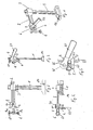
- Fig. 1 is shown in a perspective view of a clamping device with a vertical support 1, at the lower end of a foot 10 is arranged.
- a foot 10 may be arranged a base, such as a work plate.
- Alternative provisions of the carrier 1 on the base, which is not shown, are possible.
- the carrier 1 can be inserted into a corresponding recess of the base, a screw or a clamp connection are also possible as a plug connection and locking by bolts or the like.
- the foot 10 may be formed as a base.
- this can be oriented in any orientation, usually the carrier 1 is oriented perpendicular to the base, which forms a generally flat surface.
- a clamping block 3 is slidably mounted in a slot.
- the terminal block 3 is formed as a cube and has a corresponding to the cross section of the carrier 1 formed Recess on.
- a second, perpendicular thereto oriented recess for a boom 2 is provided, which is also mounted displaceably in this recess.
- the boom 2 is arranged next to the carrier 1. It is only a single boom 2 is provided, in principle it is also possible to provide two mutually parallel arms, wherein the carrier is disposed between the two arms. However, in the selected configuration of the cross-sectional shapes for the carrier 1 and the boom 2, this is not necessary, thereby the Hochkantauscardi the boom 2 and the parallel orientation of the long side of the substantially rectangular cross-section of the carrier 1 to the longitudinal extent of the boom 2 is an excellent stability and flexural rigidity of the construction is achieved.
- a bearing block 7 is arranged, on which a clamping lever 5 is pivotally mounted.
- On the bearing block 7 is also an eccentric 4, which has a rigid lever 41, rotatably mounted.
- the eccentric 4 takes place a relative displacement of the clamping lever 5 to the boom 2 in the context of possible pivoting.
- a receptacle 6 is arranged for the essay, not shown.
- the receptacle 6 may have a round cross-section, so that the receptacle can be rotatably attached to it.
- the receptacle 6 itself can be arranged to be rotatable relative to the bearing block 7, so that a rotation of the entire receptacle 6 can take place.
- the device is shown in a side view. It can be seen the orthogonal orientation of the rails of the carrier 1 and the boom 2.
- the bearing block 7 is shown with the clamping lever 5 mounted pivotably about a pivot axis 71.
- the eccentric 4 is rotatably mounted about an axis parallel to the longitudinal extent of the boom 2 on the bearing block 7.
- the receptacle 6 is fixed.
- the recording 6 is associated with an adjusting device 61, via which a height adjustment and a rotation of the receptacle 6 can take place.
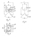
- Fig. 3 is shown in the front view of the device. It can be seen that the vertical axis of the receptacle 6 offset from the longitudinal axis of the carrier 1 extends.
- the handwheel 61 as an adjusting device is located in front of the lever 41.
- the recording 6 and / or in the FIG. 3 Not shown essay can be rotatably mounted about an axis parallel to the longitudinal extent of the clamping lever 5, so that not only one side of the essay can be oriented to the base or work surface, but several pages, for example, four pages in a cube-like essay.
- the Fig. 4 shows a plan view of the device.
- the substantially rectangular cross-section of the carrier 1 can be recognized, as can the lateral passage of the jib 2 through the clamping block 3 next to the carrier 1.
- the clamping lever 2 has a fork-like structure in the region of the bearing block 7.
- the two legs 51, 52 rest on the side of the bearing block 7 and serve as a receptacle for a bearing pin, so that a pivoting of the clamping lever 5 can take place about the pivot axis 71.
- the eccentric 4 with the lever 41 and the receptacle 6 with the adjusting device 61 shown in the form of a rotary wheel.
- Fig. 5 makes a section according to AA Fig. 2
- the two fork legs 51, 52 can be seen as well as the massive, rectangular cross section of the clamping lever. 5
- the eccentric 4 has different eccentricities 42, 43, so that depending on the direction of rotation of the lever 41, a different size displacement of the clamping lever 5 is downwards, so that the workpiece, which is to be clamped between the attachment and the base is pressed differently far in the direction of the workpiece.
- the carrier 1 is formed as a round profile, with a rotatably mounted thereon clamping block 3, which has holes in which two arms 2 are mounted on both sides next to the carrier 1 slidably.
- the booms 2 are arranged on both sides next to the carrier 1.
- a coil spring 11 is arranged in the form of a compression spring.
- a rotary wheel 12 is provided at the lower end of the carrier 1 to fix the carrier 1 to a work plate 10 or the like.
- a support plate 13 is also provided to provide a height stop for the carrier 3 in the absence of compression spring 11.
- the spring 11 can also be attached to a carrier 1 with a rectangular cross section according to the embodiment of FIGS.
- the lever 41 is configured foldable, the clamping lever 5 has in deviation from the FIG. 1 no fork-like configurations.
- an attachment 20 is arranged on the receptacle 6, not shown, which has downwardly directed profile recesses 21, 22.
- profile recesses 21, 22 workpieces can be accommodated, so that a positive fixing can be provided without clamping action.
- a variant of the adapter design provides that the attachment 20 is mounted about a substantially horizontal axis, preferably extending in the longitudinal direction of the clamping lever 5.
- the attachment 20 can then be rotated about the horizontal axis in the case of, for example, a cube-like shape, so that a total of four side surfaces with profile recesses are available in order to provide different profile recesses 21, 22. It is also possible and provided that the respective side surfaces have different hardnesses and possibly consist of different materials. This makes it possible that an improved adaptation to the workpiece to be clamped can take place. In polygonal embodiments, more than four pages may be present.
- the article can be fixed in any position, so that a secure clamping is guaranteed.
- the rotatable embodiment of the article about a horizontal axis can also in a structure according to the FIGS. 1 to 5 respectively.
- FIG. 7 shows a side view of the attachment 20 with a first profile recess 21 which is formed on the underside of the attachment 20, that is on the side facing away from the receptacle 6 of the clamping lever 5.
- a bore 26 is provided which has a diameter D, which has substantially the diameter of the round receptacle 6.
- the receptacle 6 can be inserted into the bore 26.
- a thread 23 is provided, through which a fixing pin, such as a screw, in the direction of the not shown, introduced receptacle 6 can be moved. This allows the attachment 20 securely on the recording 6 are set.
- the profile recess 21 is formed as a right-angled cutout, which is arranged continuously, that is perpendicular to the plane of the drawing.
- a continuous groove 25 is shown with a width D, which corresponds substantially to the width of the clamping lever 5, so that a fixation by the insertion of the clamping lever 5 in the groove 25 is possible.
- FIG. 8 is a rotated by 90 ° representation of the essay 20 compared to FIG. 7 shown.
- a profile recess 22 formed at the bottom in the form of a rectangular recess.
- a parallel to the profile recess 22 and the top extending groove 25 in turn serves as a receptacle for the clamping lever 5.
- the representations in the FIGS. 7 and 8 show that the attachment 20 has a rectangular contour, wherein the width B is less than the length L.
- FIG. 9 a plan view of the attachment 20, the bore 26 for the receptacle 6 with the diameter P is also shown as the grooves 25 which extend at right angles and the threaded bore 23, wherein a plurality of threaded bores 23 are provided to the receptacle 6 in the bore 26 to fix.
- the receptacle 6 is rotatably mounted within the bore 26, so that a free alignment of the attachment 20 and thus also the profile recesses 22 is possible.
Landscapes
- Engineering & Computer Science (AREA)
- Mechanical Engineering (AREA)
- Clamps And Clips (AREA)
- Jigs For Machine Tools (AREA)
Applications Claiming Priority (1)
| Application Number | Priority Date | Filing Date | Title |
|---|---|---|---|
| DE102010004739A DE102010004739A1 (de) | 2010-01-14 | 2010-01-14 | Vorrichtung zum Klemmen von Werkstücken auf einer Basis |
Publications (2)
| Publication Number | Publication Date |
|---|---|
| EP2345507A2 true EP2345507A2 (fr) | 2011-07-20 |
| EP2345507A3 EP2345507A3 (fr) | 2012-12-12 |
Family
ID=43598338
Family Applications (1)
| Application Number | Title | Priority Date | Filing Date |
|---|---|---|---|
| EP11000191A Withdrawn EP2345507A3 (fr) | 2010-01-14 | 2011-01-12 | Dispositif de serrage de pièces usinées sur une base |
Country Status (2)
| Country | Link |
|---|---|
| EP (1) | EP2345507A3 (fr) |
| DE (1) | DE102010004739A1 (fr) |
Cited By (10)
| Publication number | Priority date | Publication date | Assignee | Title |
|---|---|---|---|---|
| CN103692257A (zh) * | 2013-12-23 | 2014-04-02 | 浙江西菱股份有限公司 | 工件压紧装置和具有上述装置的钻床工作台 |
| ES2503517A1 (es) * | 2013-04-03 | 2014-10-06 | José Antonio TEJERO LÓPEZ | Dispositivo de sujeción para bancos de trabajo y otros usos |
| CN105643311A (zh) * | 2014-11-28 | 2016-06-08 | 发那科株式会社 | 对工件的多个部位进行按压的工件固定装置 |
| CN106840073A (zh) * | 2017-03-30 | 2017-06-13 | 苏州中顺瑞泰汽车检具有限公司 | 一种汽车零部件检测装置 |
| CN108772610A (zh) * | 2018-07-18 | 2018-11-09 | 沈阳奇隆汽车零部件制造有限责任公司 | 一种金属件挤丝定位锁止机构 |
| CN109318171A (zh) * | 2018-10-17 | 2019-02-12 | 江西中城通达新能源装备有限公司 | 一种密封条定位安装工装 |
| CN110125700A (zh) * | 2019-03-26 | 2019-08-16 | 武汉船用机械有限责任公司 | 燃气轮机机匣的偏心凸台的定位工装 |
| RU204488U1 (ru) * | 2021-02-19 | 2021-05-26 | Публичное акционерное общество "КАМАЗ" | Приспособление для зажима деталей |
| WO2023249617A1 (fr) * | 2022-06-21 | 2023-12-28 | Fireball Tool Works Llc | Pince modulaire |
| US12179324B2 (en) | 2022-06-21 | 2024-12-31 | Fireball Tool Works Llc | Modular clamp |
Families Citing this family (3)
| Publication number | Priority date | Publication date | Assignee | Title |
|---|---|---|---|---|
| CN106112853B (zh) * | 2016-07-18 | 2018-01-16 | 若宇检具股份有限公司 | 一种定位伸缩机构 |
| US10343242B2 (en) | 2016-09-27 | 2019-07-09 | GM Global Technology Operations LLC | Reconfigurable fastener multi-spindle tool and method |
| CN111558909B (zh) * | 2020-07-16 | 2020-10-09 | 常熟昆仑智能科技有限公司 | 一种主板一键式快速固定结构 |
Citations (1)
| Publication number | Priority date | Publication date | Assignee | Title |
|---|---|---|---|---|
| EP1479481A1 (fr) | 2002-02-01 | 2004-11-24 | José Antonio Tejero Lopez | Banc de travail portable |
Family Cites Families (6)
| Publication number | Priority date | Publication date | Assignee | Title |
|---|---|---|---|---|
| FR373559A (fr) * | 1907-01-14 | 1907-05-18 | Jean Chantel | Dispositif de serrage |
| DE1187199B (de) * | 1961-12-06 | 1965-02-11 | Eugen Mayer Dr Ing | Spannvorrichtung fuer Rohre |
| US3245289A (en) * | 1964-08-12 | 1966-04-12 | John W Nelson | Hold-down clamp assemblage |
| DE3911334A1 (de) * | 1989-04-07 | 1990-01-04 | Leo Schwer | Universal winkel-gehrungs spann- und schraubzwinge |
| US6431534B1 (en) * | 2000-08-17 | 2002-08-13 | Advanced Pneumatics | Clamping tool for aligning tubes |
| US6412764B1 (en) * | 2000-08-30 | 2002-07-02 | Ajh Enterprises | Portable pipe fitting table |
-
2010
- 2010-01-14 DE DE102010004739A patent/DE102010004739A1/de not_active Ceased
-
2011
- 2011-01-12 EP EP11000191A patent/EP2345507A3/fr not_active Withdrawn
Patent Citations (1)
| Publication number | Priority date | Publication date | Assignee | Title |
|---|---|---|---|---|
| EP1479481A1 (fr) | 2002-02-01 | 2004-11-24 | José Antonio Tejero Lopez | Banc de travail portable |
Cited By (14)
| Publication number | Priority date | Publication date | Assignee | Title |
|---|---|---|---|---|
| ES2503517A1 (es) * | 2013-04-03 | 2014-10-06 | José Antonio TEJERO LÓPEZ | Dispositivo de sujeción para bancos de trabajo y otros usos |
| WO2014162022A1 (fr) * | 2013-04-03 | 2014-10-09 | Tejero López José Antonio | Dispositif de fixation pour établis et autres usages |
| CN103692257A (zh) * | 2013-12-23 | 2014-04-02 | 浙江西菱股份有限公司 | 工件压紧装置和具有上述装置的钻床工作台 |
| CN103692257B (zh) * | 2013-12-23 | 2016-03-02 | 浙江西菱股份有限公司 | 工件压紧装置和具有上述装置的钻床工作台 |
| US9751172B2 (en) | 2014-11-28 | 2017-09-05 | Fanuc Corporation | Workpiece fastening device for pressing plurality of locations of workpiece |
| CN105643311A (zh) * | 2014-11-28 | 2016-06-08 | 发那科株式会社 | 对工件的多个部位进行按压的工件固定装置 |
| CN106840073A (zh) * | 2017-03-30 | 2017-06-13 | 苏州中顺瑞泰汽车检具有限公司 | 一种汽车零部件检测装置 |
| CN108772610A (zh) * | 2018-07-18 | 2018-11-09 | 沈阳奇隆汽车零部件制造有限责任公司 | 一种金属件挤丝定位锁止机构 |
| CN108772610B (zh) * | 2018-07-18 | 2024-05-03 | 沈阳奇隆汽车零部件制造有限责任公司 | 一种金属件挤丝定位锁止机构 |
| CN109318171A (zh) * | 2018-10-17 | 2019-02-12 | 江西中城通达新能源装备有限公司 | 一种密封条定位安装工装 |
| CN110125700A (zh) * | 2019-03-26 | 2019-08-16 | 武汉船用机械有限责任公司 | 燃气轮机机匣的偏心凸台的定位工装 |
| RU204488U1 (ru) * | 2021-02-19 | 2021-05-26 | Публичное акционерное общество "КАМАЗ" | Приспособление для зажима деталей |
| WO2023249617A1 (fr) * | 2022-06-21 | 2023-12-28 | Fireball Tool Works Llc | Pince modulaire |
| US12179324B2 (en) | 2022-06-21 | 2024-12-31 | Fireball Tool Works Llc | Modular clamp |
Also Published As
| Publication number | Publication date |
|---|---|
| EP2345507A3 (fr) | 2012-12-12 |
| DE102010004739A1 (de) | 2011-07-21 |
Similar Documents
| Publication | Publication Date | Title |
|---|---|---|
| EP2345507A2 (fr) | Dispositif de serrage de pièces usinées sur une base | |
| EP0324022B1 (fr) | Dispositif de positionnement | |
| EP3003198B1 (fr) | Dispositif adaptateur pour table d'opération | |
| EP0369197A1 (fr) | Crampon pour connecter des panneaux de coffrage | |
| DE2107374C3 (de) | Verankerung von Gleisschienen | |
| DE20118884U1 (de) | Mit Füßen versehene, verschwenkbare Platte | |
| DE2419637B2 (de) | Gelenk-stativ | |
| WO2016020028A1 (fr) | Boulon pour serrer des pièces placées l'une contre l'autre | |
| EP0614729B1 (fr) | Dispositif de serrage pour serrer des pièces à usiner sur des tables de machine-outil ou sur des palettes | |
| CH623771A5 (fr) | ||
| DE1148053B (de) | Greifvorrichtung | |
| EP2283972B1 (fr) | Elément de fixation | |
| EP0065036B1 (fr) | Table à dessus réglable | |
| DE102010025978B4 (de) | Stativkopf-Anordnung | |
| EP2195103B1 (fr) | Planche de glisse sur neige comportant une fixation | |
| AT10348U1 (de) | Prismenstabstativ | |
| WO1992002700A1 (fr) | Dispositif de montage de l'huisserie d'une porte dans l'ouverture d'un mur | |
| DE10227612B4 (de) | Fahrrad-Flaschenhalter | |
| EP2092846B1 (fr) | Table | |
| DE4140421C2 (de) | Vorrichtung zum Biegen einer aus Längsstäben und Querstäben bestehenden Baustahlmatte | |
| WO1986001267A1 (fr) | Systeme a bras oscillants | |
| DE2216438A1 (de) | Fotografisches stativ | |
| DE4338179C2 (de) | Hebelspannzwinge | |
| DE19613167A1 (de) | Gerät zum Ausrichten einer Türzarge innerhalb einer Türöffnung einer Gebäudewand | |
| DE102008045975A1 (de) | Spannvorrichtung |
Legal Events
| Date | Code | Title | Description |
|---|---|---|---|
| PUAI | Public reference made under article 153(3) epc to a published international application that has entered the european phase |
Free format text: ORIGINAL CODE: 0009012 |
|
| AK | Designated contracting states |
Kind code of ref document: A2 Designated state(s): AL AT BE BG CH CY CZ DE DK EE ES FI FR GB GR HR HU IE IS IT LI LT LU LV MC MK MT NL NO PL PT RO RS SE SI SK SM TR |
|
| AX | Request for extension of the european patent |
Extension state: BA ME |
|
| PUAL | Search report despatched |
Free format text: ORIGINAL CODE: 0009013 |
|
| AK | Designated contracting states |
Kind code of ref document: A3 Designated state(s): AL AT BE BG CH CY CZ DE DK EE ES FI FR GB GR HR HU IE IS IT LI LT LU LV MC MK MT NL NO PL PT RO RS SE SI SK SM TR |
|
| AX | Request for extension of the european patent |
Extension state: BA ME |
|
| RIC1 | Information provided on ipc code assigned before grant |
Ipc: B25B 5/00 20060101AFI20121107BHEP Ipc: B25B 5/16 20060101ALI20121107BHEP Ipc: B25B 5/08 20060101ALI20121107BHEP Ipc: B25B 5/14 20060101ALI20121107BHEP Ipc: B23Q 3/06 20060101ALI20121107BHEP |
|
| STAA | Information on the status of an ep patent application or granted ep patent |
Free format text: STATUS: THE APPLICATION IS DEEMED TO BE WITHDRAWN |
|
| 18D | Application deemed to be withdrawn |
Effective date: 20130613 |