EP2345523B1 - Récipient décoré raccordable à des pompes sans air et son procédé de fabrication - Google Patents
Récipient décoré raccordable à des pompes sans air et son procédé de fabrication Download PDFInfo
- Publication number
- EP2345523B1 EP2345523B1 EP11150731.5A EP11150731A EP2345523B1 EP 2345523 B1 EP2345523 B1 EP 2345523B1 EP 11150731 A EP11150731 A EP 11150731A EP 2345523 B1 EP2345523 B1 EP 2345523B1
- Authority
- EP
- European Patent Office
- Prior art keywords
- bag
- container
- cavity
- preform
- sheet
- Prior art date
- Legal status (The legal status is an assumption and is not a legal conclusion. Google has not performed a legal analysis and makes no representation as to the accuracy of the status listed.)
- Active
Links
Images

Classifications
-
- B—PERFORMING OPERATIONS; TRANSPORTING
- B65—CONVEYING; PACKING; STORING; HANDLING THIN OR FILAMENTARY MATERIAL
- B65D—CONTAINERS FOR STORAGE OR TRANSPORT OF ARTICLES OR MATERIALS, e.g. BAGS, BARRELS, BOTTLES, BOXES, CANS, CARTONS, CRATES, DRUMS, JARS, TANKS, HOPPERS, FORWARDING CONTAINERS; ACCESSORIES, CLOSURES, OR FITTINGS THEREFOR; PACKAGING ELEMENTS; PACKAGES
- B65D23/00—Details of bottles or jars not otherwise provided for
- B65D23/02—Linings or internal coatings
-
- A—HUMAN NECESSITIES
- A45—HAND OR TRAVELLING ARTICLES
- A45D—HAIRDRESSING OR SHAVING EQUIPMENT; EQUIPMENT FOR COSMETICS OR COSMETIC TREATMENTS, e.g. FOR MANICURING OR PEDICURING
- A45D34/00—Containers or accessories specially adapted for handling liquid toiletry or cosmetic substances, e.g. perfumes
- A45D34/02—Scent flasks, e.g. with evaporator
-
- B—PERFORMING OPERATIONS; TRANSPORTING
- B05—SPRAYING OR ATOMISING IN GENERAL; APPLYING FLUENT MATERIALS TO SURFACES, IN GENERAL
- B05B—SPRAYING APPARATUS; ATOMISING APPARATUS; NOZZLES
- B05B11/00—Single-unit hand-held apparatus in which flow of contents is produced by the muscular force of the operator at the moment of use
- B05B11/0005—Components or details
- B05B11/0037—Containers
- B05B11/0038—Inner container disposed in an outer shell or outer casing
-
- B—PERFORMING OPERATIONS; TRANSPORTING
- B05—SPRAYING OR ATOMISING IN GENERAL; APPLYING FLUENT MATERIALS TO SURFACES, IN GENERAL
- B05B—SPRAYING APPARATUS; ATOMISING APPARATUS; NOZZLES
- B05B11/00—Single-unit hand-held apparatus in which flow of contents is produced by the muscular force of the operator at the moment of use
- B05B11/01—Single-unit hand-held apparatus in which flow of contents is produced by the muscular force of the operator at the moment of use characterised by the means producing the flow
- B05B11/02—Membranes or pistons acting on the contents inside the container, e.g. follower pistons
- B05B11/026—Membranes separating the content remaining in the container from the atmospheric air to compensate underpressure inside the container
-
- B—PERFORMING OPERATIONS; TRANSPORTING
- B29—WORKING OF PLASTICS; WORKING OF SUBSTANCES IN A PLASTIC STATE IN GENERAL
- B29C—SHAPING OR JOINING OF PLASTICS; SHAPING OF MATERIAL IN A PLASTIC STATE, NOT OTHERWISE PROVIDED FOR; AFTER-TREATMENT OF THE SHAPED PRODUCTS, e.g. REPAIRING
- B29C49/00—Blow-moulding, i.e. blowing a preform or parison to a desired shape within a mould; Apparatus therefor
- B29C49/24—Lining or labelling
-
- B—PERFORMING OPERATIONS; TRANSPORTING
- B29—WORKING OF PLASTICS; WORKING OF SUBSTANCES IN A PLASTIC STATE IN GENERAL
- B29C—SHAPING OR JOINING OF PLASTICS; SHAPING OF MATERIAL IN A PLASTIC STATE, NOT OTHERWISE PROVIDED FOR; AFTER-TREATMENT OF THE SHAPED PRODUCTS, e.g. REPAIRING
- B29C49/00—Blow-moulding, i.e. blowing a preform or parison to a desired shape within a mould; Apparatus therefor
- B29C49/42—Component parts, details or accessories; Auxiliary operations
- B29C49/62—Venting means
-
- B—PERFORMING OPERATIONS; TRANSPORTING
- B05—SPRAYING OR ATOMISING IN GENERAL; APPLYING FLUENT MATERIALS TO SURFACES, IN GENERAL
- B05B—SPRAYING APPARATUS; ATOMISING APPARATUS; NOZZLES
- B05B11/00—Single-unit hand-held apparatus in which flow of contents is produced by the muscular force of the operator at the moment of use
- B05B11/01—Single-unit hand-held apparatus in which flow of contents is produced by the muscular force of the operator at the moment of use characterised by the means producing the flow
- B05B11/10—Pump arrangements for transferring the contents from the container to a pump chamber by a sucking effect and forcing the contents out through the dispensing nozzle
-
- B—PERFORMING OPERATIONS; TRANSPORTING
- B29—WORKING OF PLASTICS; WORKING OF SUBSTANCES IN A PLASTIC STATE IN GENERAL
- B29C—SHAPING OR JOINING OF PLASTICS; SHAPING OF MATERIAL IN A PLASTIC STATE, NOT OTHERWISE PROVIDED FOR; AFTER-TREATMENT OF THE SHAPED PRODUCTS, e.g. REPAIRING
- B29C49/00—Blow-moulding, i.e. blowing a preform or parison to a desired shape within a mould; Apparatus therefor
- B29C49/24—Lining or labelling
- B29C2049/2404—Lining or labelling inside the article
-
- B—PERFORMING OPERATIONS; TRANSPORTING
- B29—WORKING OF PLASTICS; WORKING OF SUBSTANCES IN A PLASTIC STATE IN GENERAL
- B29C—SHAPING OR JOINING OF PLASTICS; SHAPING OF MATERIAL IN A PLASTIC STATE, NOT OTHERWISE PROVIDED FOR; AFTER-TREATMENT OF THE SHAPED PRODUCTS, e.g. REPAIRING
- B29C2949/00—Indexing scheme relating to blow-moulding
- B29C2949/07—Preforms or parisons characterised by their configuration
- B29C2949/0715—Preforms or parisons characterised by their configuration the preform having one end closed
-
- B—PERFORMING OPERATIONS; TRANSPORTING
- B29—WORKING OF PLASTICS; WORKING OF SUBSTANCES IN A PLASTIC STATE IN GENERAL
- B29C—SHAPING OR JOINING OF PLASTICS; SHAPING OF MATERIAL IN A PLASTIC STATE, NOT OTHERWISE PROVIDED FOR; AFTER-TREATMENT OF THE SHAPED PRODUCTS, e.g. REPAIRING
- B29C2949/00—Indexing scheme relating to blow-moulding
- B29C2949/30—Preforms or parisons made of several components
- B29C2949/3086—Interaction between two or more components, e.g. type of or lack of bonding
- B29C2949/3094—Interaction between two or more components, e.g. type of or lack of bonding preform having at least partially loose components, e.g. at least partially loose layers
-
- B—PERFORMING OPERATIONS; TRANSPORTING
- B29—WORKING OF PLASTICS; WORKING OF SUBSTANCES IN A PLASTIC STATE IN GENERAL
- B29C—SHAPING OR JOINING OF PLASTICS; SHAPING OF MATERIAL IN A PLASTIC STATE, NOT OTHERWISE PROVIDED FOR; AFTER-TREATMENT OF THE SHAPED PRODUCTS, e.g. REPAIRING
- B29C49/00—Blow-moulding, i.e. blowing a preform or parison to a desired shape within a mould; Apparatus therefor
- B29C49/02—Combined blow-moulding and manufacture of the preform or the parison
- B29C49/06—Injection blow-moulding
-
- B—PERFORMING OPERATIONS; TRANSPORTING
- B29—WORKING OF PLASTICS; WORKING OF SUBSTANCES IN A PLASTIC STATE IN GENERAL
- B29C—SHAPING OR JOINING OF PLASTICS; SHAPING OF MATERIAL IN A PLASTIC STATE, NOT OTHERWISE PROVIDED FOR; AFTER-TREATMENT OF THE SHAPED PRODUCTS, e.g. REPAIRING
- B29C49/00—Blow-moulding, i.e. blowing a preform or parison to a desired shape within a mould; Apparatus therefor
- B29C49/24—Lining or labelling
- B29C49/2408—In-mould lining or labelling
-
- B—PERFORMING OPERATIONS; TRANSPORTING
- B29—WORKING OF PLASTICS; WORKING OF SUBSTANCES IN A PLASTIC STATE IN GENERAL
- B29K—INDEXING SCHEME ASSOCIATED WITH SUBCLASSES B29B, B29C OR B29D, RELATING TO MOULDING MATERIALS OR TO MATERIALS FOR MOULDS, REINFORCEMENTS, FILLERS OR PREFORMED PARTS, e.g. INSERTS
- B29K2023/00—Use of polyalkenes or derivatives thereof as moulding material
- B29K2023/04—Polymers of ethylene
- B29K2023/06—PE, i.e. polyethylene
-
- B—PERFORMING OPERATIONS; TRANSPORTING
- B29—WORKING OF PLASTICS; WORKING OF SUBSTANCES IN A PLASTIC STATE IN GENERAL
- B29K—INDEXING SCHEME ASSOCIATED WITH SUBCLASSES B29B, B29C OR B29D, RELATING TO MOULDING MATERIALS OR TO MATERIALS FOR MOULDS, REINFORCEMENTS, FILLERS OR PREFORMED PARTS, e.g. INSERTS
- B29K2023/00—Use of polyalkenes or derivatives thereof as moulding material
- B29K2023/10—Polymers of propylene
- B29K2023/12—PP, i.e. polypropylene
-
- B—PERFORMING OPERATIONS; TRANSPORTING
- B29—WORKING OF PLASTICS; WORKING OF SUBSTANCES IN A PLASTIC STATE IN GENERAL
- B29K—INDEXING SCHEME ASSOCIATED WITH SUBCLASSES B29B, B29C OR B29D, RELATING TO MOULDING MATERIALS OR TO MATERIALS FOR MOULDS, REINFORCEMENTS, FILLERS OR PREFORMED PARTS, e.g. INSERTS
- B29K2067/00—Use of polyesters or derivatives thereof, as moulding material
-
- B—PERFORMING OPERATIONS; TRANSPORTING
- B29—WORKING OF PLASTICS; WORKING OF SUBSTANCES IN A PLASTIC STATE IN GENERAL
- B29K—INDEXING SCHEME ASSOCIATED WITH SUBCLASSES B29B, B29C OR B29D, RELATING TO MOULDING MATERIALS OR TO MATERIALS FOR MOULDS, REINFORCEMENTS, FILLERS OR PREFORMED PARTS, e.g. INSERTS
- B29K2709/00—Use of inorganic materials not provided for in groups B29K2703/00 - B29K2707/00, for preformed parts, e.g. for inserts
- B29K2709/08—Glass
-
- B—PERFORMING OPERATIONS; TRANSPORTING
- B29—WORKING OF PLASTICS; WORKING OF SUBSTANCES IN A PLASTIC STATE IN GENERAL
- B29L—INDEXING SCHEME ASSOCIATED WITH SUBCLASS B29C, RELATING TO PARTICULAR ARTICLES
- B29L2009/00—Layered products
- B29L2009/001—Layered products the layers being loose
-
- B—PERFORMING OPERATIONS; TRANSPORTING
- B65—CONVEYING; PACKING; STORING; HANDLING THIN OR FILAMENTARY MATERIAL
- B65D—CONTAINERS FOR STORAGE OR TRANSPORT OF ARTICLES OR MATERIALS, e.g. BAGS, BARRELS, BOTTLES, BOXES, CANS, CARTONS, CRATES, DRUMS, JARS, TANKS, HOPPERS, FORWARDING CONTAINERS; ACCESSORIES, CLOSURES, OR FITTINGS THEREFOR; PACKAGING ELEMENTS; PACKAGES
- B65D2203/00—Decoration means, markings, information elements, contents indicators
- B65D2203/02—Labels
Definitions
- the present invention relates to a container associable with a manually operable pump for dispensing fluid substances contained under airtight conditions in a deformable bag housed in a rigid body.
- sealing the fluid out of contact with the atmosphere is important if the composition of the fluid within the container is not to undergo alteration, or if it is essential that the fluid substance enclosed in the container remains sterile.
- JP 05 031790A and JP 05 031791A published on 09/02/1993 describe how a bag of elastically deformable material can be produced directly within a rigid container. The bag is then coupled to a hermetic (airless) pump and deforms during pump delivery.
- an elongated preform (made of thermoplastic material and having an elongated hollow cylindrical body, open at one end where the preform presents a neck from which a flange radially projects) is inserted into a rigid container having a mouth from which a neck extends, on the free edge of which there rests the flange of the preform, which is heated, thrust towards the container base by a pusher and then inflated within the container, until a bag forms, the outer surface of which adheres (at least for a large part of its surface) to the inner surface of the container.
- the bag obtained in this manner also has a neck, at least an end portion of which presents outwardly projecting longitudinal ribs, with some radial ribs or projections projecting from that surface of the preform flange which faces the free edge of the neck of the container in which the bag is inserted: these ribs or projections define passages for the air which penetrates from the outside between the container and bag to enable this latter to flatten or inwardly deform during outward dispensing of the fluid substance through the hermetic pump, so preventing the formation inside the bag of a vacuum which would prevent dispensing of the fluid substance.
- a label applied to the outside of the rigid container by gluing, not only carries the various printed information required to identify and market the product, but can also present an attractive decorative design. Applying the label is often a problem. In this respect, a further container processing step must be provided in which this label is applied to the container by gluing.
- the container is directly in contact with the external environment and can discolour (in the case of product exposure to the sun), be ruined by rubbing against the surfaces with which the container comes into contact, deform or even separate from the container.
- FR2916674-A1 describes a container having an external rigid body and a deformable bag inside directly formed in it.
- the bag presents, printed on it, some information visible form the outside of the rigid body. The information printed on the bag are thus protected from outside ambient conditions.
- US5043130-A describes how to produce a rigid container that is not subject to deformation during its use.
- a label is provided on the outside of the container and integrated in the rigid wall of the container.
- a possible deformation of the wall of the container derives in a correspondent deformation of the label that thus can make the information printed on it illegible.
- US2008/0011778 - A1 describes a fluid dispenser assembly comprising an outer receptacle including an opening, said receptacle including an inside wall defining an inside space, an internal trim disposed in the inside space and a dispenser member, such as a pump, for dispensing the fluid.
- the assembly further comprising a barrier envelope for containing the fluid, said envelope being disposed inside the internal trim so that the fluid is not in contact with said internal trim.
- the receptacle is made of a transparent or translucent material, such as glass, so that the internal trim is visible through the receptacle, and in that the internal trim is substantially opaque so as to mask at least some, and preferably all, of said barrier envelope.
- the main object of the present invention is therefore to provide a device of the stated type of easy production, in which the information present on traditional labels or the decoration formed by them is stably and indelibly associated with the container, hence preventing it from decolouration, from detachment from the container, or from undergoing damage, the information do not becoming illegible when the bag containing the product shrinks due to the dispensing of the fluid.
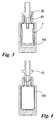
- Figure 1 represents a first step of the method of the present invention.
- an external rigid body 5 having a neck 6 defining an opening giving access to the body cavity 7.
- the neck presents an external thread 6A used to screw down a hermetic pump (by means of a ring cap) as described hereinafter.
- the body 6 is formed at least partially of transparent material, such as transparent plastic or glass.
- a preform 8 is provided, formed by moulding a plastic material, such as PE, PET, PP or the like, or by co-injection moulding various layers of mutually different materials.
- the preform 8 comprises a lowerly rounded elongated body. It also comprises a neck 2 from which a flange 3 radially extends. Teeth (not shown), the use of which is clarified hereinafter, extend from the outer part of the neck.
- a decorative sheet 100 is also provided. It is rolled up and inserted through the opening in the rigid body, before inserting the preform.
- the decorative sheet is apart (detached) from the opening of the container.
- the opening of the container is not provided with the decorative sheet, so that the opening is free from the decorative sheet. This allows an easier access to the interior of the cavity.
- the decorative sheet can have a length equal to the inner perimeter of the rigid body or less.
- the height HL of the sheet 100 can be equal to or lower than the height of the rigid body cavity.
- the height of the rigid body cavity is indicated as HM in fig 1 , and it is substantially the maximum distance between the internal base surface 101 of the cavity and the ceiling 102 of the cavity.
- the cavity of the container 5 is defined by a cylindrical surface connected by chamfered parts to the base 101 and to the ceiling 102.
- the cylindrical surface is represented by a rectilinear line 104 chamfered at the conjunctions 105 with the base and the ceiling.
- the height of the cylindrical surface corresponds to the length of the rectilinear line 104.
- the height HL of the sheet 100 is equal or lower than the height HR of the cylindrical surface present in the cavity. This allows the sheet to lie perfectly only on a cylindrical surface avoiding the formation of winkles in the sheet during the expansion of the bag In fact if the sheet is pushed against the chamfers of the cavity, the formation of wrinkles is certain.
- the decorative sheet can present, preferably on that surface facing the rigid body, a series of decorations, information relative to the product contained in the bottle, trademarks, writings of any kind or any other information or decoration which is usually printed on a normal label glued to a container.
- the sheet can be made of different materials which possess elastic properties such that it can be unrolled from the rolled-up position. Paper supports could be used protected by a covering of various plastic materials such as PE or PS, or other materials.
- the sheet could also be made completely of pre-printed plastic laminate, formed of materials able to be decorated by automatic equipment such as lithography, offset etc.
- the advantages would be those of being able to decorate the sheet and place it in the container interior such as to prevent its contact with the product, hence without particular chemical compatibility requirements.
- Another possibility would be to place in the container interior a sheet with an included microchip (represented in dotted lines only in Fig. 1 ), for example of the RFID type containing information relative to the product, or a metal antitheft band 109 or the like. The sheet cannot be removed in any manner without breaking the container.
- the sheet can evidently be made of coloured or transparent material. Moreover it could be moulded with high or low relief, with metal inserts such as holograms or the like.
- the transverse body dimensions of the preform 8 are such that it can be freely inserted into the rigid body 5, with the free ends of the teeth substantially in contact with the inner surface of the bore through the neck 6, while the preform neck 2 is profiled and has dimensions such that it easily penetrates into the bore in the neck 6 of the body 5, with the free ends of the teeth being substantially in contact with the inner surface of the hole in the neck 6, and the projecting flange 3 of the preform resting on the end of the neck 6 but without sealedly adhering to it because spaced-apart radial ribs or projections (also not shown) project from the lower surface (with respect to Figure 1 ) of the flange 3. This is possible because the opening is free from the sheet 100.
- the chamber 7 is in free communication with the outside.
- the preform is heated to a temperature sufficient to soften (plasticize) the plastic material forming the preform.
- a temperature sufficient to soften (plasticize) the plastic material forming the preform.
- it is heated, by way of example, to a temperature of 120oC for a time between 4 and 7 seconds.
- the preform flange 3 rests on the edge of the neck 6 of the body 5.
- a nozzle 20 is inserted into the preform and is sealedly connected to the neck 2 of the preform 8.
- the sealed connection is made in known manner.
- a first air jet is then fed into the preform to inflate the preform 8 such as to form a bag 8 (indicated by the same reference numeral as the preform) which at least partially occupies said body cavity ( Figure 2 ).
- the inflating air or fluid fed into the preform interior has a pressure between 2 and 10 bar, depending on the preform thickness, but preferably 3 bar.
- the air jet feed into the preform lasts for about 0.5 - 1 second.
- the jet air is at ambient temperature, but can also be hotter depending on requirements.
- feeding air into the preform causes the bag to inflate and unroll the sheet 100, then to urge it into contact with the walls of the cavity 7.
- the bag swells until the pressure of the air trapped within the interspace which forms between the bag and the walls of the cavity 7 reaches a value equal to the pressure of the air fed into the preform.
- the bag inflation can hence be only partial.
- the bag is maintained under pressure while the air present in the interspace is allowed to seep from some part towards the container neck, much higher inflation pressures being used to accelerate air seepage.
- the initial air jet is interrupted to nullify (i.e. by making it equal to the external pressure) the pressure within the bag.
- the compressed air present in the interspace 7A hence squashes the bag to separate it from the walls defining the cavity, and seeps upwards to emerge from the neck. This procedure causes the bag to substantially separate from the container inner walls.
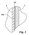
- Figure 5 shows an enlargement of the situation which arises during this step, and also in the step of Figure 2 .
- the bag is in contact with the sheet 100 which is squeezed and pressed against the wall defining the cavity of the container 5.
- a bag inflation method has been described and illustrated comprising two inflation stages. Essentially two successive jets are fed, spaced apart by suitable pauses. This cycle has a duration of about 4-7 seconds for a container of 30 ml.
- More successive jets may be required, depending on the container and bag dimensions.
- the air injection step and the subsequent jet interruption to enable venting of the air situated in the interspace outside the bag can be repeated as many times as required.
- At least one air venting step can be provided, and hence at least one interruption in the air jet for inflating the bag. Consequently at least two inflation jets will be provided, spaced apart by at least one inflation pause or interruption.
- the successive air jets fed into the bag can have a constant pressure (for example 3 bar as indicated above), or can have a pressure which varies depending on the current inflation step.
- the first jet fed into the bag can have a lower pressure than the final maintaining jet, or vice versa. Consequently pressure regulation can be optimized, even with differences between one jet and the next, to obtain maximum possible uniformity of bag thickness.
- the user receiving the container 5 with the bag 8 ( Figure 4 ) and the sheet 100 already inserted and retained in it introduces into the bag (through the opening in its neck 2) the desired quantity of fluid substance, which can fill the bag as far as its neck 2.
- the said user then inserts into the bag 8, through the opening in its neck, a manually operable pump having a dispensing stem (which projects to the outside of the bag 8 and of the container 5) and a dip tube which is immersed in the fluid substance contained in the bag.
- the pump P is then locked securely onto the neck 6 of the container in known manner, for example by a ring cap N having an internal thread which is screwed onto threads or helical ribs 6A projecting from the outside of the container neck 6.
- the ring cap N rests on the upper surface of a collar which projects radially from the pump body and presses it into sealed contact with the flange 3 of the neck 2 of the bag 8, hence pressing the lower part of the pump into the cavity of the bag neck 2 where it forms a seal, this seal being further improved by an elastic ring positioned immediately below the collar.
- the container 5 can evidently be made of any rigid or substantially rigid material (in addition to glass), for example of aluminium or other metal, or of rigid plastic.
- the interspace be in contact with the external environment, for example via the described passages formed between the container neck and the bag neck, below the flange.
- One or more holes for air passage can however be provided in the container, as illustrated in U.S. 3,420,413 and U.S. 2004/0112921 A1 , in any position therein.
- the bag presents means (i.e. the flange 3) for connection to a ring cap for fixing said pump to said container.
- These means for example, engage the ring cap thread and enable the bag to be extracted from the body 5 during removal of the ring cap (and hence of the pump) from the container.
- a very thin layer of adhesive material can be provided on the outer surface 100A of the sheet.
- the sheet when the bag presses the sheet 100 against the inner surface defining the cavity of the body 5, the sheet remains attached to the inner perimeter of the cavity.
- the bag in dispensing the product by an airless pump, the bag is made to undergo squeezing and deformation so that it separates from the container walls, to slacken and finally cease its pressure against the sheet.
- the sheet can be formed with an opaque finish or surface, which prevents the bag from being seen from the outside during its deformation.
- a lubricant fluid can be applied either to the inner surface 100B of the sheet or to the outer surface 8A of the preform.
Landscapes
- Engineering & Computer Science (AREA)
- Mechanical Engineering (AREA)
- Manufacturing & Machinery (AREA)
- Blow-Moulding Or Thermoforming Of Plastics Or The Like (AREA)
- Medicines Containing Material From Animals Or Micro-Organisms (AREA)
Claims (11)
- Procédé de fabrication de contenant, comprenant les étapes suivantes :a. la fourniture d'un corps rigide externe (5) comportant un col (6) définissant une ouverture donnant accès à la cavité du corps,b. la fourniture d'une préforme formée de matériau thermoplastique, la préforme comprenant un col (2) à partir duquel une bride (3) s'étend radialement,c. le chauffage de ladite préforme jusqu'à une température supérieure au point de ramollissement du matériau thermoplastique,d. l'agencement de la préforme dans l'ouverture du corps (5) de sorte que ladite bride repose sur un bord libre du col (6) du corps (5),e. l'injection, à l'intérieur de la préforme, d'au moins un jet d'air qui gonfle la préforme pour former un sac qui occupe au moins partiellement ladite cavité du corps, caractérisé parf. avant l'agencement de la préforme dans l'ouverture du corps (5), l'insertion dans ce dernier, à travers ladite ouverture, d'une feuille décorative et/ou informative au moins partiellement enroulée faite de matériau flexible, la feuille décorative ou informative présentant une hauteur (HL) égale ou inférieure à la hauteur de la cavité (HM) dans sa partie comprise entre une base (101) et un plafond (105) dans la cavité, le plafond présentant ladite ouverture, les parois dudit sac s'agrandissant durant l'étape de gonflage de préforme pour pousser la feuille décorative en contact avec les parois définissant ladite cavité, la feuille restant coincée entre ledit sac et les parois définissant la cavité, afin d'être visible à travers le corps externe.
- Procédé selon la revendication précédente, dans lequel, après l'étape de l'injection d'un jet d'air à l'intérieur de la préforme, les étapes supplémentaires suivantes sont prévues :a. l'interruption dudit premier jet afin de permettre audit matériau thermoplastique de rétrécir, avec en conséquence sa séparation des parois de contenant, pour ainsi permettre la sortie de l'air comprimé par l'expansion du sac et coincé entre le sac et les parois définissant ladite cavité,b. le soufflage, dans le sac, d'un jet d'air final, ledit jet d'air final gonflant complètement le sac afin de le faire entrer en contact, par l'intermédiaire de la feuille, sensiblement avec chaque point d'au moins la surface latérale intérieure de la cavité, etc. l'interruption du jet d'air.
- Procédé selon la revendication précédente, dans lequel, après l'interruption du jet d'air et tout en attendant le rétrécissement du sac, un jet d'air supplémentaire est injecté à l'intérieur de la préforme pour la gonfler davantage de sorte qu'elle occupe ladite cavité du corps dans une mesure encore plus importante, les parois dudit sac étant également dans ce cas poussées en contact avec les parois définissant ladite cavité, puis ledit jet supplémentaire est interrompu pour permettre audit matériau thermoplastique de rétrécir, avec en conséquence sa séparation des parois de contenant, pour ainsi permettre une sortie supplémentaire de l'air comprimé par l'agrandissement du sac et coincé entre le sac et les parois définissant ladite cavité.
- Procédé selon la revendication précédente, dans lequel les étapes décrites dans la revendication 3 sont répétées jusqu'à ce que le sac ait presque complètement occupé ladite cavité durant l'injection du jet.
- Procédé selon une ou plusieurs des revendications précédentes, dans lequel ledit jet d'air est interrompu après une période comprise entre 0,3 et 3 secondes, et/ou dans lequel ledit jet d'air présente une pression comprise entre 2 et 6 bars, et/ou dans lequel la préforme est chauffée jusqu'à une température comprise entre 100°C et 150°C.
- Contenant comprenant un corps sensiblement rigide (5) formé au moins partiellement de matériau transparent et comportant un col (6) définissant une ouverture fournissant un accès à la cavité du contenant, et un sac (8) positionné à l'intérieur du corps (5), le sac étant formé de matériau thermoplastique et comportant un col (2) à partir duquel s'étend radialement une bride (3) qui repose sur un bord libre du col (6) du corps (5) et qui définit un trou pour fournir un accès à la cavité du sac (8) et pour loger de façon scellée le corps d'une pompe hermétique (P) actionnable manuellement pour retirer la substance fluidique (F) du sac et la distribuer à l'extérieur à travers sa tige de distribution (S), le sac étant formé en moulant par soufflage à chaud une préforme positionnée directement à l'intérieur du contenant, une feuille décorative étant interposée entre ledit contenant et ledit sac, et étant visible à partir de l'extérieur du contenant, caractérisé en ce que l'ouverture (103) du contenant est dépourvue de la feuille décorative (100) afin de permettre un accès plus facile à la cavité du contenant, la feuille décorative présentant une hauteur (HL) égale ou inférieure à la hauteur de la cavité (HM) dans sa partie comprise entre une base (101) et un plafond (105) dans la cavité, le plafond présentant ladite ouverture.
- Contenant selon une ou plusieurs des revendications précédentes, dans lequel une micro-puce et/ou une bande antivol métallique (109) sont associées à la feuille décorative.
- Contenant ou procédé selon la revendication 1 ou 6, dans lequel la hauteur de la feuille (HL) est égale ou inférieure à la hauteur (HR) d'une surface cylindrique de la cavité s'étendant entre la base et le plafond de ladite cavité, afin d'empêcher la formation de plis dans ladite feuille (100) durant la formation du contenant.
- Contenant ou procédé selon une ou plusieurs des revendications précédentes, dans lequel le corps rigide est formé de verre, et/ou dans lequel la préforme/le sac est formé de PET et/ou de PE et/ou de PP et/ou en moulant diverses couches par co-injection.
- Contenant ou procédé selon une ou plusieurs des revendications précédentes, dans lequel ladite feuille présente, sur au moins une partie de la surface de celle-ci faisant face aux parois définissant la cavité dudit contenant, au moins une couche de matériau adhésif.
- Contenant selon une ou plusieurs des revendications précédentes, dans lequel ledit sac présente des moyens pour son raccordement à un écrou à oeil pour fixer ladite pompe audit contenant, lesdits moyens de raccordement étant tels qu'ils permettent au sac d'être extrait du corps (5) durant la dépose de l'écrou à oeil à partir du contenant.
Applications Claiming Priority (1)
| Application Number | Priority Date | Filing Date | Title |
|---|---|---|---|
| ITMI2010A000039A IT1397891B1 (it) | 2010-01-15 | 2010-01-15 | Contenitore decorato associabile a pompe airless e metodo per la sua realizzazione. |
Publications (2)
| Publication Number | Publication Date |
|---|---|
| EP2345523A1 EP2345523A1 (fr) | 2011-07-20 |
| EP2345523B1 true EP2345523B1 (fr) | 2013-05-22 |
Family
ID=42671919
Family Applications (1)
| Application Number | Title | Priority Date | Filing Date |
|---|---|---|---|
| EP11150731.5A Active EP2345523B1 (fr) | 2010-01-15 | 2011-01-12 | Récipient décoré raccordable à des pompes sans air et son procédé de fabrication |
Country Status (4)
| Country | Link |
|---|---|
| US (1) | US8875425B2 (fr) |
| EP (1) | EP2345523B1 (fr) |
| IT (1) | IT1397891B1 (fr) |
| RU (1) | RU2011101426A (fr) |
Families Citing this family (9)
| Publication number | Priority date | Publication date | Assignee | Title |
|---|---|---|---|---|
| IT1398945B1 (it) * | 2010-03-17 | 2013-03-28 | Lumson Spa | Metodo per la realizzazione di un contenitore da utilizzare con una pompa ermetica. |
| DE102011100560B3 (de) * | 2011-05-05 | 2012-03-15 | Leibinger Smb Technik Gmbh | Vorrichtung zum Befüllen eines Behältnisses mit einer zum Verzehr bestimmten Flüssigkeit |
| KR101258142B1 (ko) * | 2011-06-30 | 2013-04-25 | (주)연우 | 내용물의 리필이 가능한 지관용기 |
| IT201800004619A1 (it) * | 2018-04-17 | 2019-10-17 | Contenitore di un prodotto cosmetico o medicale | |
| JP6757528B2 (ja) * | 2018-07-23 | 2020-09-23 | Nissha株式会社 | 導電回路付成形品とその製造方法、および導電回路付プリフォームとその製造方法 |
| ES2911638T3 (es) * | 2019-04-24 | 2022-05-20 | Ctl Th Packaging S L Unipersonal | Envase tubular con un tubo exterior y un contenedor interior |
| GB202008502D0 (en) | 2020-06-05 | 2020-07-22 | Alpert Joseph | Environmentally Substainable product dispenser |
| IT202000027618A1 (it) * | 2020-11-18 | 2022-05-18 | Lumson Spa | Dispositivo di erogazione di una sostanza fluida |
| IT202300009144A1 (it) * | 2023-05-08 | 2024-11-08 | Lumson Spa | Dispositivo di erogazione di una sostanza fluida |
Family Cites Families (29)
| Publication number | Priority date | Publication date | Assignee | Title |
|---|---|---|---|---|
| US3420413A (en) | 1967-08-14 | 1969-01-07 | Diamond Int Corp | Liquid and paste dispenser |
| US3626609A (en) * | 1970-07-02 | 1971-12-14 | Evan R Cramer | Costume leg extenders with natural foot covers |
| US4088336A (en) * | 1976-12-08 | 1978-05-09 | Lesley Chapel | Foot-wearable stilt |
| DE3339180C2 (de) | 1983-10-28 | 1993-10-14 | Pfeiffer Erich Gmbh & Co Kg | Austragvorrichtung für Medien |
| US4691847A (en) * | 1983-12-27 | 1987-09-08 | Realex Corporation | Pasty product dispenser having combination actuator and outlet valve |
| US5043130A (en) * | 1990-07-09 | 1991-08-27 | Fuji Seal Industry Co., Ltd. | Method of manufacturing labeled containers |
| FR2676958A1 (fr) | 1991-05-31 | 1992-12-04 | Valois | Procede de fabrication d'un recipient a coque exterieure rigide contenant une poche souple, destine notamment a la pulverisation ou a la distribution de produits fluides ou pateux sans reprise d'air. |
| JP3201417B2 (ja) | 1991-07-26 | 2001-08-20 | 株式会社吉野工業所 | 内壜形成用の二軸延伸可能な合成樹脂製ピースと、内外二重壜の成形方法および内外二重壜 |
| JP3062309B2 (ja) | 1991-07-29 | 2000-07-10 | 株式会社吉野工業所 | 内壜形成用の二軸延伸可能な合成樹脂製ピースと、内外二重壜の成形方法および内外二重壜 |
| GB9126971D0 (en) * | 1991-12-19 | 1992-02-19 | Rowan Michael G | Improvements in stilts |
| EP0601145B1 (fr) | 1992-05-22 | 1997-08-27 | MESHBERG, Philip | Sac ou doublure de barrage inserable pour receptacle de distribution a col etroit et procede de remplissage dudit sac ou de ladite doublure de barrage par le siphon tubulaire |
| JP3595571B2 (ja) | 1993-05-07 | 2004-12-02 | 日精エー・エス・ビー機械株式会社 | 二重壁ボトルとその成形方法及び装置 |
| KR100338994B1 (ko) | 1995-03-10 | 2002-06-01 | 요시노 쇼이치로 | 적층박리용기와 그 관련기술 |
| US5749460A (en) * | 1995-06-06 | 1998-05-12 | The Pillsbury Company | Undercup assembly |
| US5931416A (en) * | 1997-11-21 | 1999-08-03 | Carpenter; Howard G. | Tethered aircraft having remotely controlled angle of attack |
| IT1298131B1 (it) * | 1998-01-15 | 1999-12-20 | Capsol S P A Stampaggio Resine | Erogatore di sostanze pastose o cremose |
| DE20006423U1 (de) * | 2000-04-11 | 2000-06-15 | Fa. Helmut Steinmetz Inhaber Manfred Braun, 65795 Hattersheim | Gefäß mit Werbeelement |
| US6984425B2 (en) * | 2002-11-19 | 2006-01-10 | Raymond Mark A | Containers with integral lenticular systems and inner label inserts |
| FR2857292B1 (fr) * | 2003-07-11 | 2007-04-20 | Oreal | Recipient comportant une piece de revetement et son procede de fabrication |
| FR2859188B1 (fr) * | 2003-08-29 | 2007-06-15 | Oreal | Poche et dispositif de conditionnement comportant une poche |
| US20050068182A1 (en) * | 2003-09-30 | 2005-03-31 | Dunlap Richard L. | Application of radio frequency identification |
| FR2878835B1 (fr) * | 2004-12-02 | 2008-07-04 | Shiseido Internat France Soc P | Ensemble de distribution de produit fluide |
| US20070270288A1 (en) * | 2006-05-22 | 2007-11-22 | Phil Hansard | Portable attachment device and method for comfort and support |
| FR2902083B1 (fr) | 2006-06-13 | 2010-12-31 | Productions Realisations Plastiques | Recipient a double paroi et procede pour la realisation d'un tel recipient |
| US7703226B2 (en) * | 2006-08-11 | 2010-04-27 | Alameda Technology, Llc | Container with reflective surface for creating a multi-effect visual display |
| US7875227B2 (en) * | 2006-12-01 | 2011-01-25 | Rexam Healthcare Packaging Inc. | Molded plastic container and preform having insert-molded RFID tag |
| FR2916674A1 (fr) * | 2007-05-29 | 2008-12-05 | Augros Cosmetic Packaging Sa | Procede de fabrication d'un recipient multicouche |
| ITMI20071936A1 (it) * | 2007-10-08 | 2008-01-07 | Lumson Spa | Metodo per la realizzazione di un dispositivo per contenere a tenuta d'aria e per erogare sostanze fluide e dispositivo cosi' ottenuto |
| IT1398945B1 (it) * | 2010-03-17 | 2013-03-28 | Lumson Spa | Metodo per la realizzazione di un contenitore da utilizzare con una pompa ermetica. |
-
2010
- 2010-01-15 IT ITMI2010A000039A patent/IT1397891B1/it active
-
2011
- 2011-01-12 US US13/005,307 patent/US8875425B2/en active Active
- 2011-01-12 EP EP11150731.5A patent/EP2345523B1/fr active Active
- 2011-01-14 RU RU2011101426/05A patent/RU2011101426A/ru not_active Application Discontinuation
Also Published As
| Publication number | Publication date |
|---|---|
| US20110174764A1 (en) | 2011-07-21 |
| ITMI20100039A1 (it) | 2011-07-16 |
| EP2345523A1 (fr) | 2011-07-20 |
| RU2011101426A (ru) | 2012-07-20 |
| US8875425B2 (en) | 2014-11-04 |
| IT1397891B1 (it) | 2013-02-04 |
Similar Documents
| Publication | Publication Date | Title |
|---|---|---|
| US8875425B2 (en) | Decorated container associable with airless pumps and method for its production | |
| EP2246267B1 (fr) | Procédé de fabrication d'un récipient raccordable à des pompes sans air | |
| EP2366529B1 (fr) | Procédé de production d'un récipient pour une utilisation avec une pompe sans air | |
| EP2279848B1 (fr) | Récipient amélioré raccordable à des pompes sans air et son procédé de fabrication | |
| EP2243557B1 (fr) | Dispositif pour contenir des substances fluides de manière étanche à l'air et pour les délivrer | |
| EP2197589B1 (fr) | Dispositif pour distribuer, à l'aide d'une pompe, des substances fluides contenues dans un sac déformable renfermé dans un contenant rigide dans des conditions d'étanchéité à l'air | |
| EP2279800B1 (fr) | Cartouche de recharge comprenant un sachet muni d'un manchon de protection | |
| KR100338994B1 (ko) | 적층박리용기와 그 관련기술 | |
| CN109070432B (zh) | 容器制造方法 | |
| US5916646A (en) | Container having a decorative label and a method for obtaining this container | |
| EP2489608A1 (fr) | Récipient raccordable à des pompes sans air et muni d'un sac déformable à surface rugueuse, et son procédé de fabrication | |
| EP3603934B1 (fr) | Procédé de fabrication de récipient | |
| EP3632652B1 (fr) | Méthode de fabrication de récipient de liquide | |
| US4305772A (en) | Method for forming an interlocked assembly |
Legal Events
| Date | Code | Title | Description |
|---|---|---|---|
| PUAI | Public reference made under article 153(3) epc to a published international application that has entered the european phase |
Free format text: ORIGINAL CODE: 0009012 |
|
| AK | Designated contracting states |
Kind code of ref document: A1 Designated state(s): AL AT BE BG CH CY CZ DE DK EE ES FI FR GB GR HR HU IE IS IT LI LT LU LV MC MK MT NL NO PL PT RO RS SE SI SK SM TR |
|
| AX | Request for extension of the european patent |
Extension state: BA ME |
|
| 17P | Request for examination filed |
Effective date: 20120117 |
|
| REG | Reference to a national code |
Ref country code: DE Ref legal event code: R079 Ref document number: 602011001677 Country of ref document: DE Free format text: PREVIOUS MAIN CLASS: B29C0049240000 Ipc: B05B0011000000 |
|
| GRAP | Despatch of communication of intention to grant a patent |
Free format text: ORIGINAL CODE: EPIDOSNIGR1 |
|
| RIC1 | Information provided on ipc code assigned before grant |
Ipc: B05B 11/00 20060101AFI20120924BHEP Ipc: B29C 49/24 20060101ALI20120924BHEP Ipc: B65D 23/02 20060101ALI20120924BHEP |
|
| GRAS | Grant fee paid |
Free format text: ORIGINAL CODE: EPIDOSNIGR3 |
|
| GRAP | Despatch of communication of intention to grant a patent |
Free format text: ORIGINAL CODE: EPIDOSNIGR1 |
|
| GRAA | (expected) grant |
Free format text: ORIGINAL CODE: 0009210 |
|
| INTG | Intention to grant announced |
Effective date: 20130327 |
|
| AK | Designated contracting states |
Kind code of ref document: B1 Designated state(s): AL AT BE BG CH CY CZ DE DK EE ES FI FR GB GR HR HU IE IS IT LI LT LU LV MC MK MT NL NO PL PT RO RS SE SI SK SM TR |
|
| REG | Reference to a national code |
Ref country code: GB Ref legal event code: FG4D |
|
| REG | Reference to a national code |
Ref country code: CH Ref legal event code: EP |
|
| REG | Reference to a national code |
Ref country code: AT Ref legal event code: REF Ref document number: 612917 Country of ref document: AT Kind code of ref document: T Effective date: 20130615 |
|
| REG | Reference to a national code |
Ref country code: IE Ref legal event code: FG4D |
|
| REG | Reference to a national code |
Ref country code: DE Ref legal event code: R096 Ref document number: 602011001677 Country of ref document: DE Effective date: 20130718 |
|
| REG | Reference to a national code |
Ref country code: AT Ref legal event code: MK05 Ref document number: 612917 Country of ref document: AT Kind code of ref document: T Effective date: 20130522 |
|
| REG | Reference to a national code |
Ref country code: LT Ref legal event code: MG4D |
|
| PG25 | Lapsed in a contracting state [announced via postgrant information from national office to epo] |
Ref country code: FI Free format text: LAPSE BECAUSE OF FAILURE TO SUBMIT A TRANSLATION OF THE DESCRIPTION OR TO PAY THE FEE WITHIN THE PRESCRIBED TIME-LIMIT Effective date: 20130522 Ref country code: SE Free format text: LAPSE BECAUSE OF FAILURE TO SUBMIT A TRANSLATION OF THE DESCRIPTION OR TO PAY THE FEE WITHIN THE PRESCRIBED TIME-LIMIT Effective date: 20130522 Ref country code: AT Free format text: LAPSE BECAUSE OF FAILURE TO SUBMIT A TRANSLATION OF THE DESCRIPTION OR TO PAY THE FEE WITHIN THE PRESCRIBED TIME-LIMIT Effective date: 20130522 Ref country code: NO Free format text: LAPSE BECAUSE OF FAILURE TO SUBMIT A TRANSLATION OF THE DESCRIPTION OR TO PAY THE FEE WITHIN THE PRESCRIBED TIME-LIMIT Effective date: 20130822 Ref country code: LT Free format text: LAPSE BECAUSE OF FAILURE TO SUBMIT A TRANSLATION OF THE DESCRIPTION OR TO PAY THE FEE WITHIN THE PRESCRIBED TIME-LIMIT Effective date: 20130522 Ref country code: SI Free format text: LAPSE BECAUSE OF FAILURE TO SUBMIT A TRANSLATION OF THE DESCRIPTION OR TO PAY THE FEE WITHIN THE PRESCRIBED TIME-LIMIT Effective date: 20130522 Ref country code: GR Free format text: LAPSE BECAUSE OF FAILURE TO SUBMIT A TRANSLATION OF THE DESCRIPTION OR TO PAY THE FEE WITHIN THE PRESCRIBED TIME-LIMIT Effective date: 20130823 Ref country code: ES Free format text: LAPSE BECAUSE OF FAILURE TO SUBMIT A TRANSLATION OF THE DESCRIPTION OR TO PAY THE FEE WITHIN THE PRESCRIBED TIME-LIMIT Effective date: 20130902 Ref country code: PT Free format text: LAPSE BECAUSE OF FAILURE TO SUBMIT A TRANSLATION OF THE DESCRIPTION OR TO PAY THE FEE WITHIN THE PRESCRIBED TIME-LIMIT Effective date: 20130923 |
|
| REG | Reference to a national code |
Ref country code: NL Ref legal event code: VDEP Effective date: 20130522 |
|
| PG25 | Lapsed in a contracting state [announced via postgrant information from national office to epo] |
Ref country code: PL Free format text: LAPSE BECAUSE OF FAILURE TO SUBMIT A TRANSLATION OF THE DESCRIPTION OR TO PAY THE FEE WITHIN THE PRESCRIBED TIME-LIMIT Effective date: 20130522 Ref country code: HR Free format text: LAPSE BECAUSE OF FAILURE TO SUBMIT A TRANSLATION OF THE DESCRIPTION OR TO PAY THE FEE WITHIN THE PRESCRIBED TIME-LIMIT Effective date: 20130522 Ref country code: BG Free format text: LAPSE BECAUSE OF FAILURE TO SUBMIT A TRANSLATION OF THE DESCRIPTION OR TO PAY THE FEE WITHIN THE PRESCRIBED TIME-LIMIT Effective date: 20130822 Ref country code: RS Free format text: LAPSE BECAUSE OF FAILURE TO SUBMIT A TRANSLATION OF THE DESCRIPTION OR TO PAY THE FEE WITHIN THE PRESCRIBED TIME-LIMIT Effective date: 20130522 |
|
| PG25 | Lapsed in a contracting state [announced via postgrant information from national office to epo] |
Ref country code: LV Free format text: LAPSE BECAUSE OF FAILURE TO SUBMIT A TRANSLATION OF THE DESCRIPTION OR TO PAY THE FEE WITHIN THE PRESCRIBED TIME-LIMIT Effective date: 20130522 |
|
| PG25 | Lapsed in a contracting state [announced via postgrant information from national office to epo] |
Ref country code: EE Free format text: LAPSE BECAUSE OF FAILURE TO SUBMIT A TRANSLATION OF THE DESCRIPTION OR TO PAY THE FEE WITHIN THE PRESCRIBED TIME-LIMIT Effective date: 20130522 Ref country code: SK Free format text: LAPSE BECAUSE OF FAILURE TO SUBMIT A TRANSLATION OF THE DESCRIPTION OR TO PAY THE FEE WITHIN THE PRESCRIBED TIME-LIMIT Effective date: 20130522 Ref country code: BE Free format text: LAPSE BECAUSE OF FAILURE TO SUBMIT A TRANSLATION OF THE DESCRIPTION OR TO PAY THE FEE WITHIN THE PRESCRIBED TIME-LIMIT Effective date: 20130522 Ref country code: DK Free format text: LAPSE BECAUSE OF FAILURE TO SUBMIT A TRANSLATION OF THE DESCRIPTION OR TO PAY THE FEE WITHIN THE PRESCRIBED TIME-LIMIT Effective date: 20130522 Ref country code: CZ Free format text: LAPSE BECAUSE OF FAILURE TO SUBMIT A TRANSLATION OF THE DESCRIPTION OR TO PAY THE FEE WITHIN THE PRESCRIBED TIME-LIMIT Effective date: 20130522 |
|
| PG25 | Lapsed in a contracting state [announced via postgrant information from national office to epo] |
Ref country code: RO Free format text: LAPSE BECAUSE OF FAILURE TO SUBMIT A TRANSLATION OF THE DESCRIPTION OR TO PAY THE FEE WITHIN THE PRESCRIBED TIME-LIMIT Effective date: 20130522 Ref country code: NL Free format text: LAPSE BECAUSE OF FAILURE TO SUBMIT A TRANSLATION OF THE DESCRIPTION OR TO PAY THE FEE WITHIN THE PRESCRIBED TIME-LIMIT Effective date: 20130522 |
|
| PLBE | No opposition filed within time limit |
Free format text: ORIGINAL CODE: 0009261 |
|
| STAA | Information on the status of an ep patent application or granted ep patent |
Free format text: STATUS: NO OPPOSITION FILED WITHIN TIME LIMIT |
|
| 26N | No opposition filed |
Effective date: 20140225 |
|
| REG | Reference to a national code |
Ref country code: DE Ref legal event code: R097 Ref document number: 602011001677 Country of ref document: DE Effective date: 20140225 |
|
| PG25 | Lapsed in a contracting state [announced via postgrant information from national office to epo] |
Ref country code: LU Free format text: LAPSE BECAUSE OF FAILURE TO SUBMIT A TRANSLATION OF THE DESCRIPTION OR TO PAY THE FEE WITHIN THE PRESCRIBED TIME-LIMIT Effective date: 20140112 |
|
| REG | Reference to a national code |
Ref country code: CH Ref legal event code: PL |
|
| PG25 | Lapsed in a contracting state [announced via postgrant information from national office to epo] |
Ref country code: CH Free format text: LAPSE BECAUSE OF NON-PAYMENT OF DUE FEES Effective date: 20140131 Ref country code: LI Free format text: LAPSE BECAUSE OF NON-PAYMENT OF DUE FEES Effective date: 20140131 |
|
| REG | Reference to a national code |
Ref country code: IE Ref legal event code: MM4A |
|
| PG25 | Lapsed in a contracting state [announced via postgrant information from national office to epo] |
Ref country code: IE Free format text: LAPSE BECAUSE OF NON-PAYMENT OF DUE FEES Effective date: 20140112 |
|
| PG25 | Lapsed in a contracting state [announced via postgrant information from national office to epo] |
Ref country code: MC Free format text: LAPSE BECAUSE OF FAILURE TO SUBMIT A TRANSLATION OF THE DESCRIPTION OR TO PAY THE FEE WITHIN THE PRESCRIBED TIME-LIMIT Effective date: 20130522 |
|
| PGFP | Annual fee paid to national office [announced via postgrant information from national office to epo] |
Ref country code: GB Payment date: 20150129 Year of fee payment: 5 |
|
| REG | Reference to a national code |
Ref country code: FR Ref legal event code: PLFP Year of fee payment: 6 |
|
| PG25 | Lapsed in a contracting state [announced via postgrant information from national office to epo] |
Ref country code: MT Free format text: LAPSE BECAUSE OF FAILURE TO SUBMIT A TRANSLATION OF THE DESCRIPTION OR TO PAY THE FEE WITHIN THE PRESCRIBED TIME-LIMIT Effective date: 20130522 |
|
| PG25 | Lapsed in a contracting state [announced via postgrant information from national office to epo] |
Ref country code: SM Free format text: LAPSE BECAUSE OF FAILURE TO SUBMIT A TRANSLATION OF THE DESCRIPTION OR TO PAY THE FEE WITHIN THE PRESCRIBED TIME-LIMIT Effective date: 20130522 |
|
| PG25 | Lapsed in a contracting state [announced via postgrant information from national office to epo] |
Ref country code: IS Free format text: LAPSE BECAUSE OF FAILURE TO SUBMIT A TRANSLATION OF THE DESCRIPTION OR TO PAY THE FEE WITHIN THE PRESCRIBED TIME-LIMIT Effective date: 20130522 Ref country code: CY Free format text: LAPSE BECAUSE OF FAILURE TO SUBMIT A TRANSLATION OF THE DESCRIPTION OR TO PAY THE FEE WITHIN THE PRESCRIBED TIME-LIMIT Effective date: 20130522 |
|
| PG25 | Lapsed in a contracting state [announced via postgrant information from national office to epo] |
Ref country code: HU Free format text: LAPSE BECAUSE OF FAILURE TO SUBMIT A TRANSLATION OF THE DESCRIPTION OR TO PAY THE FEE WITHIN THE PRESCRIBED TIME-LIMIT; INVALID AB INITIO Effective date: 20110112 Ref country code: TR Free format text: LAPSE BECAUSE OF FAILURE TO SUBMIT A TRANSLATION OF THE DESCRIPTION OR TO PAY THE FEE WITHIN THE PRESCRIBED TIME-LIMIT Effective date: 20130522 |
|
| GBPC | Gb: european patent ceased through non-payment of renewal fee |
Effective date: 20160112 |
|
| PG25 | Lapsed in a contracting state [announced via postgrant information from national office to epo] |
Ref country code: GB Free format text: LAPSE BECAUSE OF NON-PAYMENT OF DUE FEES Effective date: 20160112 |
|
| REG | Reference to a national code |
Ref country code: FR Ref legal event code: PLFP Year of fee payment: 7 |
|
| REG | Reference to a national code |
Ref country code: FR Ref legal event code: PLFP Year of fee payment: 8 |
|
| PG25 | Lapsed in a contracting state [announced via postgrant information from national office to epo] |
Ref country code: MK Free format text: LAPSE BECAUSE OF FAILURE TO SUBMIT A TRANSLATION OF THE DESCRIPTION OR TO PAY THE FEE WITHIN THE PRESCRIBED TIME-LIMIT Effective date: 20130522 |
|
| PG25 | Lapsed in a contracting state [announced via postgrant information from national office to epo] |
Ref country code: AL Free format text: LAPSE BECAUSE OF FAILURE TO SUBMIT A TRANSLATION OF THE DESCRIPTION OR TO PAY THE FEE WITHIN THE PRESCRIBED TIME-LIMIT Effective date: 20130522 |
|
| P01 | Opt-out of the competence of the unified patent court (upc) registered |
Effective date: 20230626 |
|
| PGFP | Annual fee paid to national office [announced via postgrant information from national office to epo] |
Ref country code: DE Payment date: 20260128 Year of fee payment: 16 |
|
| PGFP | Annual fee paid to national office [announced via postgrant information from national office to epo] |
Ref country code: IT Payment date: 20251219 Year of fee payment: 16 |
|
| PGFP | Annual fee paid to national office [announced via postgrant information from national office to epo] |
Ref country code: FR Payment date: 20260126 Year of fee payment: 16 |